


Complete Guide to Automatic Water Level Controller Using 555 Timer
Automatic water level controllers are widely used in residential, agricultural, and industrial water management systems to automate pump operation and prevent tank overflow or dry running. Among various control solutions, circuits built around the NE555 timer remain popular because of their simplicity, reliability, and low cost.
This article provides a technical engineering analysis of a 555-timer-based automatic water level controller. It explains the working principle, sensing mechanisms, relay driving circuit, power supply design, and practical installation considerations. The goal is to give engineers and electronics enthusiasts a deeper understanding of how to design a stable and reliable controller for real-world water tank systems.
Table of Contents
- 1. What is an Automatic Water Level Controller
- 2. 555 Timer Operation in Water Level Control
- 3. System Operating Principle
- 4. Relay Driver, Pump Control, and Power Supply
- 5. Probe-Based Water Level Detection
- 6. Float Sensor Mechanical Design and Installation
- 7. Advantages and Limitations
- 8. FAQ
- 9. Conclusion
1. What is an Automatic Water Level Controller
An automatic water level controller is an electronic control system designed to regulate the operation of a water pump based on the water level inside a storage tank.
Its fundamental function is straightforward:
- Start the pump when water falls below a minimum level
- Stop the pump when water reaches the maximum level
Without automation, tanks are typically monitored manually, which often leads to:
- Water overflow
- Pump dry-running
- Excessive electricity consumption
- Increased mechanical wear
An automated controller eliminates these issues by continuously monitoring the water level and controlling the pump accordingly.
A typical system contains three major subsystems:
- Water level sensing unit
- Control logic circuit
- Pump switching interface (relay or contactor)
The 555 timer acts as the control logic element in this design.
2. 555 Timer Operation in Water Level Control
The NE555 timer IC is one of the most widely used analog integrated circuits in control electronics. Although commonly used in oscillators and timers, it can also operate as a bistable latch, which is ideal for water level control.
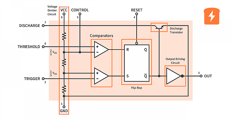
Key pins used in this circuit include:
| Pin | Name | Function |
|---|---|---|
| 2 | Trigger | Activates the pump when voltage falls below 1/3 Vcc |
| 4 | Reset | Forces the output LOW when pulled to ground |
| 3 | Output | Controls transistor and relay |
| 8 | VCC | Power supply |
| 1 | GND | Ground reference |
Bistable Operation
In this application, the 555 timer operates in bistable mode, meaning it has two stable states:
- Pump ON state
- Pump OFF state
The state changes only when a trigger or reset signal is applied. This behavior is crucial because it prevents rapid switching caused by small water fluctuations or turbulence inside the tank.
The control logic works as follows:
- Trigger pin activated → Pump ON
- Reset pin activated → Pump OFF
Once the output changes state, it remains there until the opposite input is triggered.
3. System Operating Principle
The water tank uses two level sensors:
- Low-level sensor (pump start)
- High-level sensor (pump stop)
These sensors feed signals to the trigger and reset inputs of the 555 timer.
Pump Start Condition
When water drops below the minimum threshold:
- The low-level sensor becomes active
- Trigger pin (Pin 2) goes LOW
- The 555 output switches HIGH
- Relay activates
- Pump starts filling the tank
Pump Stop Condition
When water reaches the maximum threshold:
- High-level sensor activates
- Reset pin (Pin 4) goes LOW
- Output switches LOW
- Relay releases
- Pump stops
Because the system uses two distinct sensing levels, it naturally introduces hysteresis, preventing frequent pump cycling.
4. Relay Driver, Pump Control, and Power Supply
The output of the 555 timer cannot directly drive a motor or high-current device, so an intermediate switching stage is required.
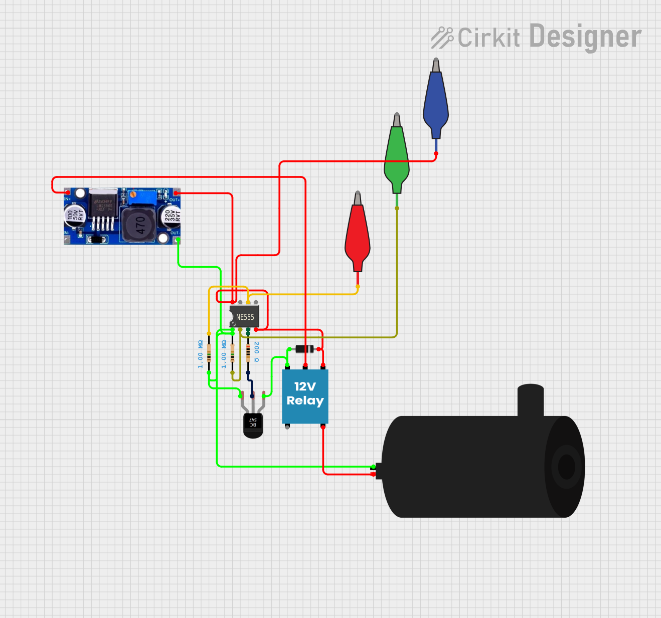
Transistor Driver Stage
An NPN transistor (such as 2N2222 or BC547) is typically used.
Operation:
- 555 output drives the transistor base through a resistor
- Transistor saturates
- Relay coil energizes
- Relay contacts switch the pump power
Flyback Protection
A flyback diode is placed across the relay coil to suppress back electromotive force (EMF) generated when the relay turns off. Without this diode, voltage spikes can damage the transistor or the 555 IC.
Pump Power Interface
For small pumps:
- A 12V relay is sufficient.
For larger pumps:
- Use a contactor rated at least 1.5× the motor current.
This ensures safe operation under startup current conditions.
Power Supply Design
A stable 12V DC supply is required.
Typical stages include:
- Step-down transformer
- Bridge rectifier
- Filter capacitor
- Voltage regulator (e.g., 7812)
Proper filtering prevents false triggering caused by electrical noise.
5. Probe-Based Water Level Detection
Instead of mechanical floats, a probe-based sensing system can be used.
This method relies on the electrical conductivity of water.
Three electrodes are installed inside the tank:
- Common probe
- Low level probe
- High level probe
Working Principle
When water contacts a probe:
- A conductive path forms between the probe and the common electrode
- A small current flows
- The control circuit detects the change
- Pump state switches accordingly
Design Considerations
To ensure reliable operation:
- Use stainless steel probes
- Keep sensing voltage below 12V
- Limit current to microampere levels
This reduces electrolysis and corrosion, extending probe life.
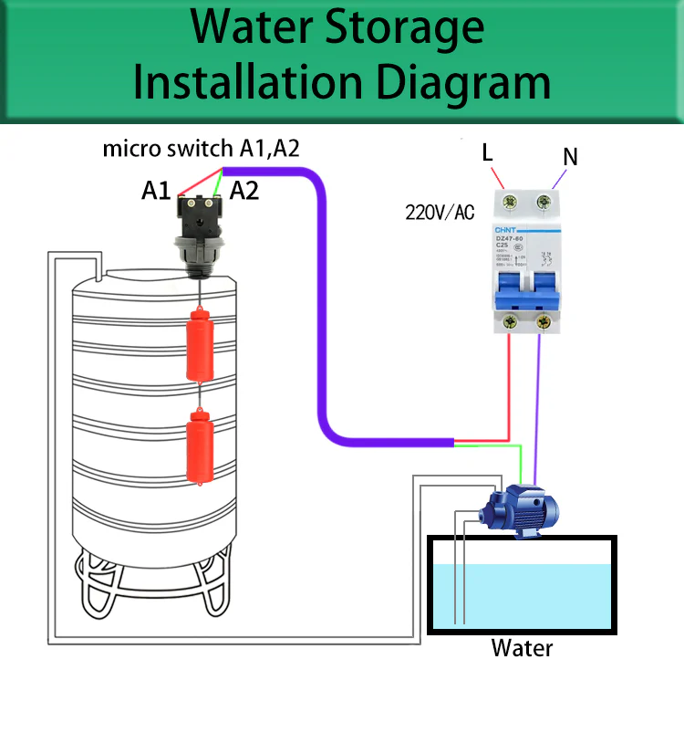
6. Float Sensor Mechanical Design and Installation
Float sensors are widely used due to their mechanical simplicity and reliability.
Sensor Length Configuration
Two floats are installed at different heights:
| Sensor | Position | Function |
|---|---|---|
| Low level float | Near tank outlet | Start pump |
| High level float | Near tank top | Stop pump |
Proper spacing between these levels ensures stable control hysteresis.
Protective PVC Housing
Floats are often installed inside a vertical PVC pipe to protect them from:
- Turbulence
- Floating debris
- Pump-induced water currents
Key construction features:
- 5 mm hole in the top cap for rod movement
- Water entry hole in bottom cap
- Smooth internal walls for frictionless motion
Pre-Installation Testing
Before installation:
- Verify float movement
- Check switch continuity with a multimeter
- Test the controller with a small load
These steps prevent installation failures.
7. Advantages and Limitations
Advantages
- Prevents tank overflow
- Protects pumps from dry running
- Reduces manual monitoring
- Saves electricity
- Extends motor lifespan
- Low maintenance requirements
Limitations
- Slightly higher initial installation cost
- Float switches may jam due to debris
- Probe sensors may corrode over time
- Very pure water has low conductivity for probe systems
- Control circuit failure stops automation
8. FAQ
1. Why is the 555 timer suitable for water level controllers?
The 555 timer can operate in bistable mode, acting like a memory latch. This allows the pump to remain ON or OFF until the opposite level sensor is triggered, preventing rapid switching.
2. Can the circuit control large industrial pumps?
Yes, but the relay must be replaced with a motor contactor rated for the pump’s current and voltage.
3. Which sensor type is more reliable: float or probe?
- Float sensors are mechanically reliable and unaffected by water conductivity.
- Probe sensors are simpler but require corrosion-resistant materials.
4. What supply voltage is recommended?
Most designs operate using 12V DC, which provides safe sensing voltage and reliable relay operation.
5. How can false triggering be avoided?
Use:
- Proper power supply filtering
- Shielded sensor wiring
- Adequate hysteresis between level sensors
These design practices significantly improve system stability.
9. Conclusion
A 555-timer-based automatic water level controller offers a simple and effective solution for managing water tanks. By combining level sensors, bistable logic, and a relay driver, the system can reliably control pump operation with minimal components.
When designed correctly, the controller can:
- Prevent water wastage
- Protect pump motors
- Reduce electricity consumption
- Improve overall system reliability
Although modern microcontroller solutions exist, the 555 timer remains a robust and low-cost option, especially for small-scale water management systems.