


DIY Subwoofer Amplifier Design: Engineering Guide to Building a High-Quality Bass Amplifier
A subwoofer amplifier is designed specifically to amplify low-frequency audio signals and drive high-power bass speakers efficiently. Compared with full-range amplifiers, subwoofer amplifiers must deliver higher current, maintain stability under low-impedance loads, and ensure minimal noise in the low-frequency band.
This guide explains the engineering principles behind a DIY subwoofer amplifier using a TL072 JFET operational amplifier as the preamplifier stage and LM1875 power amplifier ICs for the output stage. It covers circuit architecture, signal processing, power supply design, thermal management, and testing procedures. The article also discusses impedance matching, enclosure considerations, and common design mistakes that can degrade bass performance.
Table of Contents
- Subwoofer Amplifier Architecture
- Signal Flow and Circuit Operation
- Power Supply Design and Regulation
- PCB Assembly and Hardware Construction
- Amplifier Testing and Verification
- Matching the Amplifier with a Subwoofer
- Power Supply Topologies: Linear vs SMPS
- Methods to Improve Bass Performance
- Common Design and Assembly Mistakes
- FAQ
- Conclusion
Subwoofer Amplifier Architecture
A subwoofer amplifier is typically divided into two functional stages:
- Low-level signal conditioning stage (preamplifier)
- High-power amplification stage
The circuit described in this design uses:
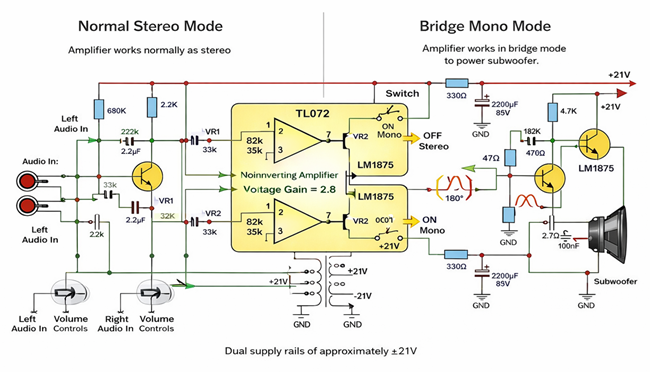
- TL072 dual JFET operational amplifier
- Two LM1875 audio power amplifier ICs
The preamplifier stage processes and conditions the audio signal before delivering it to the power amplifier, which then drives the subwoofer.
Preamplifier Stage
The TL072 is selected because of several electrical advantages:
- High input impedance (JFET input)
- Low noise density
- Wide bandwidth
- Low distortion
Typical roles of the preamp stage:
- Voltage gain for weak input signals
- Active low-pass filtering
- Impedance buffering
- Signal conditioning
In most subwoofer designs, the preamp also integrates a low-pass crossover, typically between 80 Hz and 150 Hz, ensuring only bass frequencies reach the power stage.
Power Amplifier Stage
The LM1875 is a widely used monolithic audio power amplifier capable of delivering approximately:
- 20–30 W RMS per channel
- Load impedance: 4–8 Ω
- Supply voltage: ±16V to ±30V
Two LM1875 chips can operate in:
- Stereo mode
- Bridge mode (BTL) for higher output power.
Signal Flow and Circuit Operation
Input Filtering
At the amplifier input, RC filtering networks suppress high-frequency interference and radio noise.
Typical components:
- Input resistor: 10kΩ – 47kΩ
- Input capacitor: 100nF – 1µF
These form a high-pass filter preventing DC offsets from entering the op-amp.
Voltage Gain Configuration
The TL072 operates as a non-inverting amplifier.
Voltage gain:
Av = 1 + (Rf / Rg)
Example values:
- Rf = 18kΩ
- Rg = 10kΩ
Resulting gain:
Av ≈ 2.8
This moderate gain avoids excessive noise amplification while maintaining sufficient signal amplitude for the power stage.
Bridge Mode Operation
A switch allows the circuit to operate in mono bridge configuration.
Bridge mode characteristics:
- One amplifier receives the inverted signal
- Outputs are 180° out of phase
- Voltage across the speaker doubles
Power increases approximately:
PBTL ≈ 4 × Psingle
However, the effective load impedance per amplifier becomes half, so proper thermal management is essential.
Output Stabilization (Zobel Network)
Each LM1875 output includes a Zobel network.
Typical values:
- 10Ω resistor
- 100nF capacitor
Purpose:
- Prevent high-frequency oscillations
- Stabilize reactive speaker loads
Power Supply Design and Regulation
Audio amplifiers are highly sensitive to power supply quality. Noise or ripple can directly translate into audible hum.
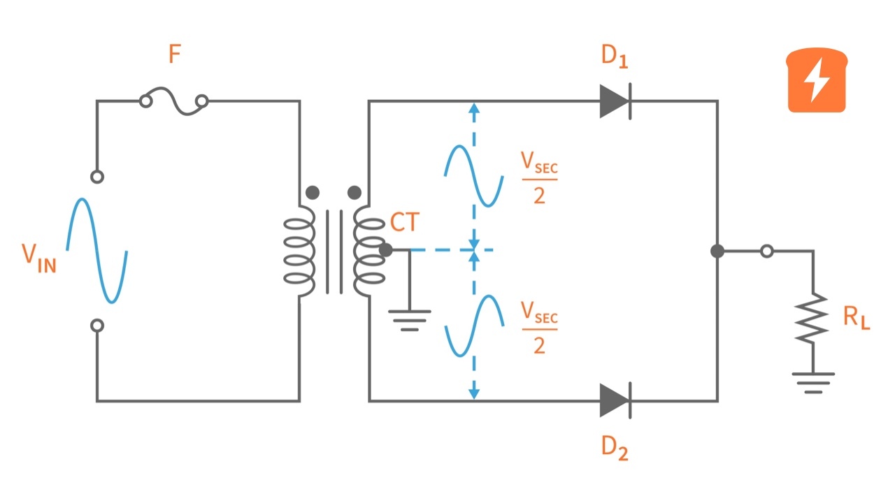
Transformer Stage
Typical specification:
- Primary: 230V AC
- Secondary: 21V-0-21V center-tapped
This configuration enables generation of dual polarity rails.
Rectification
A bridge rectifier converts AC into pulsating DC.
Peak DC voltage:
VDC ≈ VAC × √2
For 21V AC:
VDC ≈ 29.7V
After load and regulation the rails stabilize near:
±21V DC
Filtering Capacitors
Large electrolytic capacitors smooth ripple.
Typical values:
- 4700µF – 10000µF per rail
Ripple voltage:
Vripple = I / (f × C)
Lower ripple improves bass clarity.
Low-Voltage Regulation for Preamp
The TL072 operates optimally around:
±12V
This voltage is derived using:
- Zener diodes
- Series resistors
Advantages:
- Lower noise
- Improved op-amp stability
- Reduced distortion
PCB Assembly and Hardware Construction
Proper physical construction strongly affects amplifier performance.
Recommended Assembly Order
- Resistors and small signal diodes
- Ceramic capacitors
- Electrolytic capacitors
- IC sockets
- Connectors and potentiometers
Thermal Management
Each LM1875 can dissipate roughly 20–30 W under heavy load.
Required heatsink thermal resistance:
Rθ < 3°C/W
Recommended practices:
- Use thermal paste
- Use insulated mica pads
- Ensure airflow inside enclosure
Wiring Layout
Important layout principles include:
- Separate signal ground and power ground
- Keep input wires short
- Place transformer away from preamp circuits
- Twist AC wires to reduce electromagnetic interference
Amplifier Testing and Verification
Initial Inspection
Before powering the circuit:
- Inspect solder joints
- Verify component orientation
- Confirm capacitor polarity
Power Rail Measurement
Using a multimeter verify:
- +21V rail
- −21V rail
Rails should be symmetrical and stable.
Output DC Offset Check
Measure amplifier output with no signal applied.
Safe operating range:
DC offset < 50 mV
Higher values can damage speakers.
Functional Test
Steps:
- Connect a dummy load or test speaker
- Inject a low-level audio signal
- Slowly increase volume
Observe:
- Clean waveform
- No audible hum
- No clipping
- Stable heatsink temperature
Matching the Amplifier with a Subwoofer
Correct electrical matching ensures efficiency and reliability.
Impedance Matching
Typical subwoofer impedances:
- 4Ω
- 8Ω
Using a lower impedance than the amplifier rating increases current draw and may cause overheating.
Power Matching
Example:
Amplifier output: 30W RMS
Recommended speaker rating:
30W–50W RMS
This prevents both underpowering and speaker damage.
Sensitivity
Speaker sensitivity is defined as:
SPL (dB/W/m)
Higher sensitivity speakers produce more sound using less power.
Power Supply Topologies: Linear vs SMPS
| Feature | Linear Power Supply | Switch Mode Power Supply (SMPS) |
|---|---|---|
| Efficiency | Low | High |
| Noise | Very low | May introduce switching noise |
| Size | Large transformer | Compact |
| Complexity | Simple design | More complex circuitry |
| Typical Use | Hi-Fi audio amplifiers | High-power modern amplifiers |
High-power subwoofer amplifiers often use SMPS supplies capable of generating rails around ±60V.
Methods to Improve Bass Performance
Several engineering optimizations significantly improve bass response.
Correct Crossover Frequency
Typical subwoofer crossover range:
80 Hz – 120 Hz
This prevents midrange frequencies from entering the subwoofer.
Optimized Speaker Enclosure
Two common designs:
Sealed enclosure
Provides tight and accurate bass response.
Ported enclosure
Provides deeper bass and higher efficiency.
High-Capacity Power Filtering
Larger capacitors improve transient current delivery during bass peaks.
Proper Grounding
Star-ground layouts eliminate ground loop noise.
Short Signal Paths
Short shielded cables prevent interference pickup.
Common Design and Assembly Mistakes
Incorrect Component Orientation
Reversed electrolytic capacitors can fail catastrophically and damage nearby components.
Poor Soldering
Cold solder joints create unstable electrical connections and introduce noise.
Insufficient Heat Sinking
Power ICs may enter thermal shutdown or fail permanently.
Weak Power Supply
Undersized transformers cause voltage sag and distortion during heavy bass passages.
Poor Ground Layout
Ground loops can introduce audible 50/60 Hz hum.
FAQ
Why use TL072 instead of a standard op-amp?
The TL072 uses JFET input transistors which provide higher input impedance and lower noise compared with many bipolar-input op-amps.
Can LM1875 drive a 4Ω subwoofer?
Yes, but adequate heatsinking and sufficient power supply current are required.
Is bridge mode always better?
Bridge mode increases power output but also increases current draw and thermal stress.
How large should filter capacitors be?
Typical designs use 4700µF to 10000µF per power rail.
What usually causes hum in DIY amplifiers?
The most common causes include poor grounding, insufficient filtering, and transformer magnetic coupling.
Conclusion
Building a DIY subwoofer amplifier requires careful attention to circuit topology, power supply design, thermal management, and speaker matching. By combining a TL072 low-noise preamplifier with LM1875 power amplifier stages, builders can construct a reliable medium-power amplifier capable of producing clean and powerful bass.
Proper PCB layout, adequate filtering capacitors, and correct speaker impedance matching are essential to achieving stable performance. When these engineering considerations are applied correctly, a DIY subwoofer amplifier can rival many commercial audio systems in both sound quality and reliability.