


Drone Circuit Boards: Components, Architecture, and Advanced Flight Control Technology
Drone circuit boards—commonly referred to as flight controller PCBs—form the central electronic architecture of modern unmanned aerial vehicles (UAVs). These boards integrate sensing, signal processing, motor control, power management, and wireless communication into a compact embedded system.
From a systems engineering perspective, the drone PCB operates as a real-time control platform that processes data from inertial sensors, interprets pilot commands, executes stabilization algorithms, and distributes power to propulsion subsystems.
This article provides a technical engineering analysis of drone circuit boards, covering architecture, signal processing pipelines, subsystem design, communication interfaces, typical failure modes, and emerging trends in UAV electronics and PCB manufacturing.
Table of Contents
- 1. What Is a Drone Circuit Board?
- 2. How a Drone Circuit Board Works
- 3. Core Components of a Drone Flight Controller
- 4. Types of Circuit Boards Used in Drones
- 5. Signal Processing Pipeline in Drone Electronics
- 6. Power Distribution and Power Management
- 7. Communication Systems on Drone Circuit Boards
- 8. Common Drone PCB Failures and Troubleshooting
- 9. Repairing a Damaged Drone Circuit Board
- 10. Upgrading and Modifying Drone Circuit Boards
- 11. Emerging Trends in Drone Electronics and PCB Technology
- 12. FAQ
- 13. Conclusion
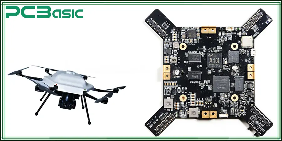
1. What Is a Drone Circuit Board?
A drone circuit board is the main embedded electronic system responsible for flight control, navigation, signal processing, and subsystem coordination in a UAV.
In most modern drones, this board is known as the flight controller (FC). It integrates multiple electronic subsystems including:
- Microcontroller or embedded processor
- Inertial measurement unit (IMU)
- Power regulation circuits
- Motor control interfaces
- Communication modules
- Peripheral sensor interfaces
From a system architecture perspective, the flight controller acts as a closed-loop control system. It constantly measures the drone’s physical state (position, velocity, orientation) and adjusts motor output to maintain stable flight.
2. How a Drone Circuit Board Works
A drone flight controller operates through a real-time feedback control loop. This loop typically runs at 500 Hz – 8 kHz, depending on the firmware and hardware capabilities.
Control Loop Stages
- Input acquisition
- Sensor fusion
- Control algorithm processing
- Motor output generation
- Feedback correction
Sensor Fusion
The controller collects data from multiple sensors:
- Gyroscope
- Accelerometer
- Magnetometer
- Barometer
- GPS module
These inputs are fused using algorithms such as:
- Kalman filters
- Complementary filters
- Mahony / Madgwick filters
This process generates an accurate estimate of the drone’s attitude and position.
PID Flight Control
Most drones rely on PID control loops:
[ Output = K_p \cdot e + K_i \int e,dt + K_d \frac{de}{dt} ]
Where:
- (e) = error between desired and measured orientation
- (K_p) = proportional gain
- (K_i) = integral gain
- (K_d) = derivative gain
These parameters regulate how aggressively the drone corrects its motion.
3. Core Components of a Drone Flight Controller
A drone circuit board integrates multiple functional modules.
Microcontroller / Processor
The processor is the computational core of the drone.
Common MCU families include:
- STM32 series
- ARM Cortex-M processors
Key responsibilities:
- Running flight firmware
- Executing control algorithms
- Handling sensor fusion
- Managing communication protocols
Inertial Measurement Unit (IMU)
The IMU typically integrates:
- 3-axis gyroscope
- 3-axis accelerometer
These sensors measure angular velocity and linear acceleration.
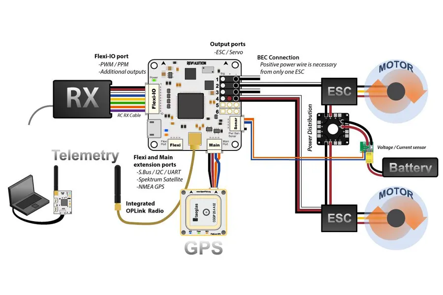
Motor Control Interfaces
Flight controllers output signals to ESCs (Electronic Speed Controllers) via:
- PWM
- OneShot
- DShot digital protocols
Power Regulation Circuits
Voltage regulators convert battery voltage into stable rails:
- 5V rail
- 3.3V logic rail
Peripheral Interfaces
Typical interfaces include:
- UART
- SPI
- I²C
- CAN bus (advanced drones)
4. Types of Circuit Boards Used in Drones
Drone electronics are typically divided into several specialized PCB modules.
Flight Controller Board
Handles:
- sensor processing
- control algorithms
- flight stabilization
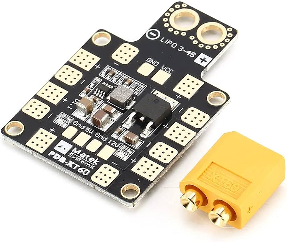
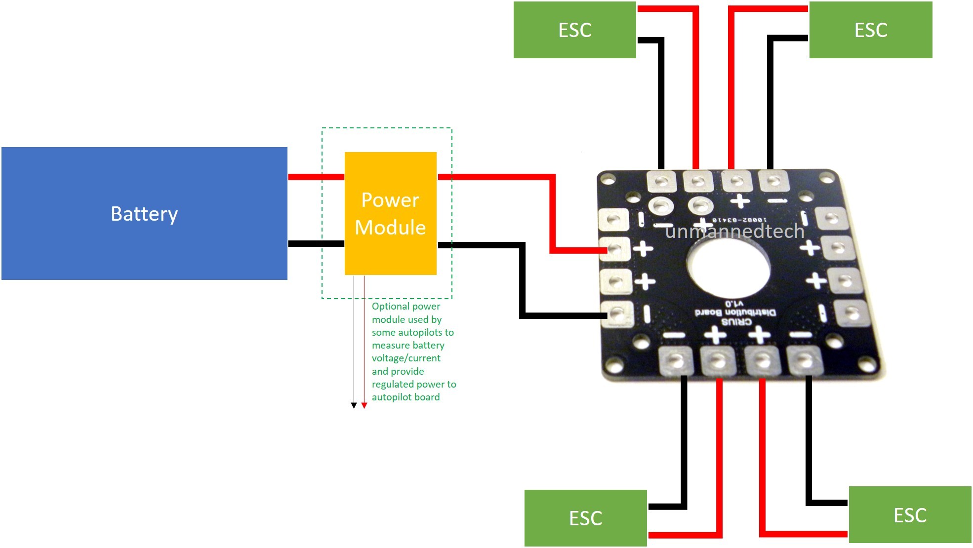
Power Distribution Board (PDB)
Distributes battery power to:
- ESCs
- flight controller
- payload electronics
ESC Board
ESCs convert DC battery power into three-phase motor drive signals.
GPS Board
Provides:
- position tracking
- navigation
- return-to-home functionality
Video / Camera Board
Handles:
- image capture
- FPV transmission
- telemetry overlays
5. Signal Processing Pipeline in Drone Electronics
Signal processing inside a drone flight controller follows a structured pipeline.
1. Signal Reception
Inputs include:
- Remote controller signals
- IMU data
- GPS data
- telemetry signals
2. Sensor Fusion
Raw sensor signals are noisy and must be filtered.
Common filtering techniques include:
- Low-pass filters
- Kalman filters
- Complementary filters
3. Control Algorithm Execution
Control firmware computes desired motor thrust adjustments.
4. Motor Output
Commands are transmitted to ESCs via digital or PWM signals.
5. Stabilization Feedback
The loop repeats continuously to maintain stable flight dynamics.
6. Power Distribution and Power Management
Power architecture is critical for drone reliability.
Battery Source
Most drones use LiPo batteries ranging from:
- 2S (7.4V)
- 4S (14.8V)
- 6S (22.2V)
Voltage Regulation
DC-DC converters generate stable voltages:
- 5V for logic systems
- 3.3V for sensors
Current Distribution
Power buses deliver energy to:
- motors
- controllers
- payload electronics
Proper PCB design must consider:
- copper trace width
- thermal dissipation
- current capacity
7. Communication Systems on Drone Circuit Boards
Drone PCBs support multiple communication subsystems.
Remote Control Link
Typical radio protocols include:
- SBUS
- CRSF
- DSMX
These transmit pilot commands to the flight controller.
GPS Communication
GPS modules connect via UART.
Data includes:
- latitude
- longitude
- altitude
- velocity
Telemetry
Telemetry sends real-time data to the ground station:
- battery voltage
- flight mode
- altitude
- signal strength
Video Transmission
FPV drones transmit video via:
- analog 5.8 GHz
- digital HD systems
8. Common Drone PCB Failures and Troubleshooting
| Problem | Possible Cause | Engineering Solution |
|---|---|---|
| Drone not powering on | Battery or voltage regulator failure | Check battery voltage and power rails |
| Overheating components | Short circuit or excessive current | Inspect PCB traces and cooling |
| Unstable flight | Sensor drift or calibration error | Recalibrate IMU sensors |
| Weak signal | Antenna or receiver issue | Check antenna and receiver wiring |
| Burnt components | ESC or power surge damage | Replace damaged components |
| Motor failure | Broken ESC signal line | Check ESC connections |
9. Repairing a Damaged Drone Circuit Board
Repairing a drone PCB requires careful diagnostics.
1. Visual Inspection
Check for:
- burnt ICs
- damaged capacitors
- broken connectors
2. Cleaning
Use:
- isopropyl alcohol
- anti-static brushes
3. Electrical Testing
Test circuits with:
- multimeter
- oscilloscope
4. Component Replacement
Replace faulty parts such as:
- regulators
- capacitors
- connectors
5. Solder Joint Repair
Cold solder joints can cause intermittent faults.
6. Functional Testing
Final verification should include:
- motor test
- sensor calibration
- flight test
10. Upgrading and Modifying Drone Circuit Boards
Advanced users often upgrade drone electronics.
Common modifications include:
- installing faster microcontrollers
- adding optical flow sensors
- integrating LiDAR modules
- upgrading ESC protocols
- adding long-range telemetry modules
Benefits include:
- improved flight stability
- longer flight range
- better navigation capability
However, modifications require careful consideration of:
- power consumption
- firmware compatibility
- PCB layout limitations
11. Emerging Trends in Drone Electronics and PCB Technology
Drone electronics are rapidly evolving.
High-Density PCB Design
Modern UAV boards use:
- multi-layer PCBs
- HDI technology
- fine-pitch components
AI-Enabled Flight Controllers
Artificial intelligence enables:
- obstacle avoidance
- autonomous navigation
- object tracking
5G Communication
5G improves:
- real-time video streaming
- low-latency remote control
Advanced Materials
New PCB materials improve:
- thermal management
- signal integrity
3D Electronic Packaging
Stacked PCB designs reduce size and weight.
12. FAQ
What does a drone flight controller do?
A flight controller processes sensor data and pilot commands to control motor speed, allowing the drone to maintain balance and navigate accurately.
Why are IMU sensors important in drones?
IMU sensors measure motion and orientation, enabling the controller to stabilize the aircraft during flight.
Can a drone work without GPS?
Yes. Many drones can fly using only IMU sensors, although GPS improves navigation and enables autonomous features.
What causes drone PCB failure most often?
Common causes include:
- power surges
- moisture damage
- overheating
- mechanical impact
13. Conclusion
Drone circuit boards represent the central intelligence and control infrastructure of modern UAV systems. By integrating sensing, control algorithms, power management, and communication interfaces, the flight controller enables stable and responsive flight.
As UAV applications expand—from aerial photography to industrial inspection and autonomous logistics—the underlying electronics continue to evolve. Advances in AI integration, high-density PCB design, and high-speed communication technologies are driving the next generation of drone platforms, making them more autonomous, efficient, and capable than ever before.