


Understanding Optomechanical Design: Principles, Engineering Process, and Real-World Applications
Optomechanical design is the engineering discipline that integrates optical components with mechanical structures to ensure precise alignment, stability, and long-term reliability. Even micron-level displacement caused by thermal expansion, vibration, or mechanical stress can degrade optical performance.
This article explains the fundamental principles of optomechanical engineering, the typical design workflow, thermal and tolerance considerations, and the role of simulation tools such as finite element analysis (FEA). It also discusses common design challenges and emerging trends in high-precision optical systems used in cameras, lasers, aerospace instruments, and medical imaging devices.
Table of Contents
- 1. Understanding Optomechanical Design
- 2. Why Mechanical Engineering Is Critical in Optical Systems
- 3. Core Engineering Steps in Optomechanical Design
- 4. Collaborative Optomechanical Development Process
- 5. Thermal Effects in Optical Assemblies
- 6. Tolerance Analysis in Optical System Integration
- 7. Simulation in Optomechanical Engineering
- 8. Finite Element Analysis (FEA) for Structural Validation
- 9. Common Engineering Problems in Optomechanical Design
- 10. Future Trends in Optomechanical Systems
- 11. FAQ
- 12. Conclusion
1. Understanding Optomechanical Design
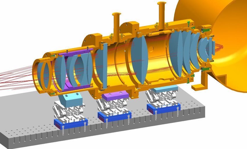
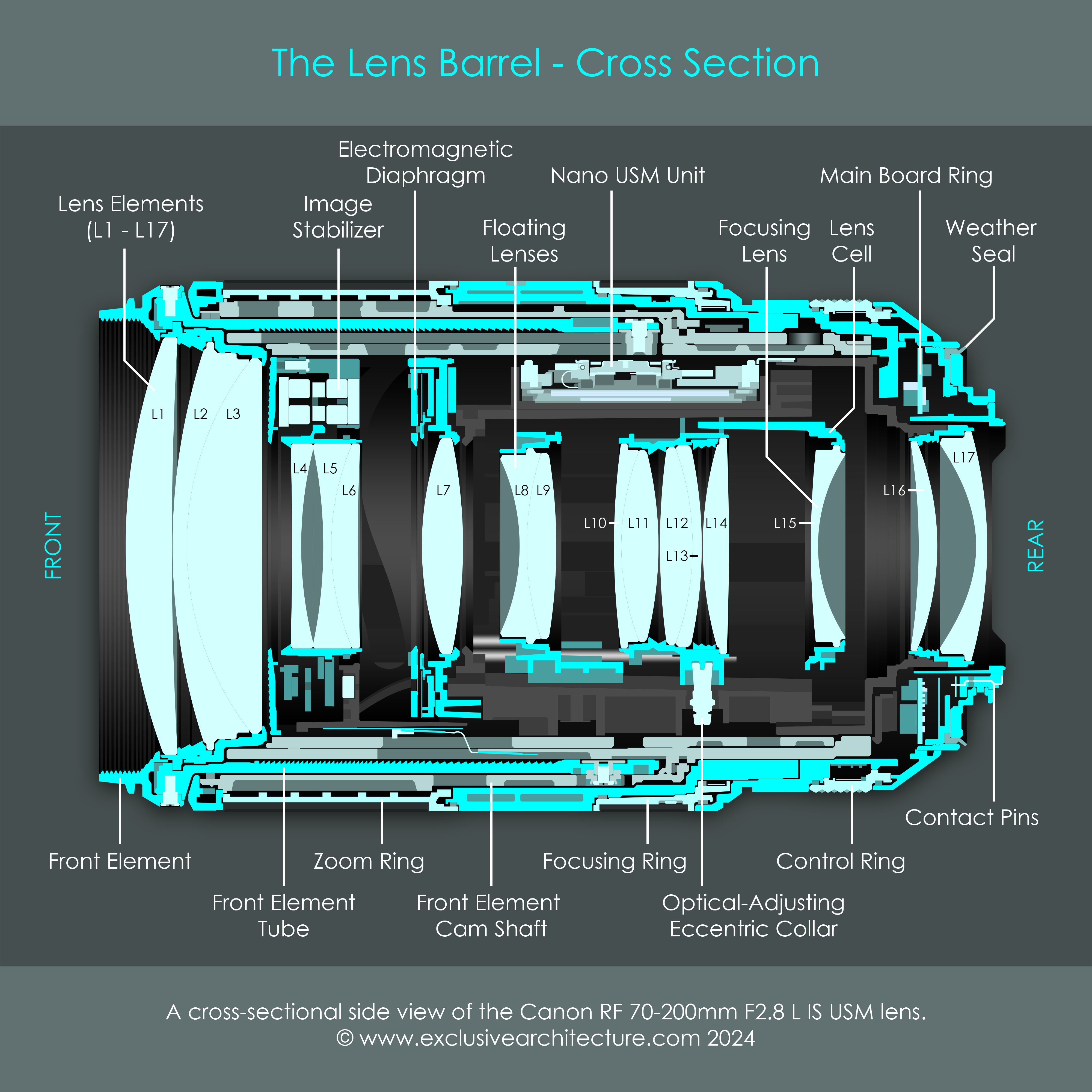
Optomechanical design is the engineering process of integrating optical elements (lenses, mirrors, prisms, sensors) with mechanical structures that position, support, and protect them.
The primary objective is to maintain precise optical alignment under real operating conditions including:
- temperature changes
- mechanical vibration
- structural loads
- environmental exposure
Unlike theoretical optical design, which focuses on light paths and imaging performance, optomechanical engineering ensures that the physical implementation preserves optical accuracy throughout the product lifecycle.
Typical optomechanical systems include:
- camera lens assemblies
- laser systems
- telescopes
- lidar sensors
- optical microscopes
- medical imaging equipment
Small mechanical deviations—often only a few micrometers—can introduce aberrations, misalignment, or focus drift. Therefore, mechanical design must account for thermal expansion, mechanical stiffness, and assembly tolerances.
2. Why Mechanical Engineering Is Critical in Optical Systems
Mechanical design is fundamental to the performance of any precision optical instrument. The mechanical structure determines how well the optical components maintain their alignment over time.
Alignment Stability
Optical performance depends on accurate positioning of components along six degrees of freedom:
- X, Y, Z translation
- Pitch, yaw, roll rotation
Even minimal displacement may cause:
- focus shift
- optical aberrations
- beam deviation
A rigid and well-designed structure maintains alignment throughout environmental changes.
Environmental Protection
Optical instruments frequently operate in challenging conditions:
- vibration during transportation
- thermal cycling
- mechanical shock
- humidity or contamination
Mechanical enclosures and mounts protect sensitive optics from these influences.
Manufacturability and Assembly
A well-designed optomechanical system must also be practical to manufacture and assemble.
Engineering considerations include:
- precision machining tolerances
- alignment features (dowels, reference surfaces)
- adjustment mechanisms
- modular component design
These features reduce assembly complexity and improve production consistency.
3. Core Engineering Steps in Optomechanical Design
Once the optical layout is defined, engineers begin translating it into a mechanical architecture. This process typically involves five key engineering stages.
3.1 Material Selection
Material properties strongly influence optical alignment stability.
Key parameters include:
- Coefficient of Thermal Expansion (CTE)
- elastic modulus
- density
- thermal conductivity
Common materials used in optomechanics include:
| Material | Key Advantages |
|---|---|
| Aluminum alloys | Lightweight and easy to machine |
| Stainless steel | High strength and durability |
| Titanium | Excellent strength-to-weight ratio |
| Invar | Extremely low thermal expansion |
Matching the CTE of mounts and optical components minimizes thermal misalignment.
Surface treatments such as anodizing or passivation may also be required to reduce corrosion and stray reflections.
3.2 Structural Design
The mechanical structure must ensure:
- high stiffness
- minimal deformation
- effective vibration resistance
Engineers often use:
- ribbed structures
- lightweight frames
- monolithic housings
Dynamic components like focus mechanisms may incorporate:
- precision lead screws
- stepper motors
- linear actuators
The structure must maintain alignment while minimizing mass and manufacturing complexity.
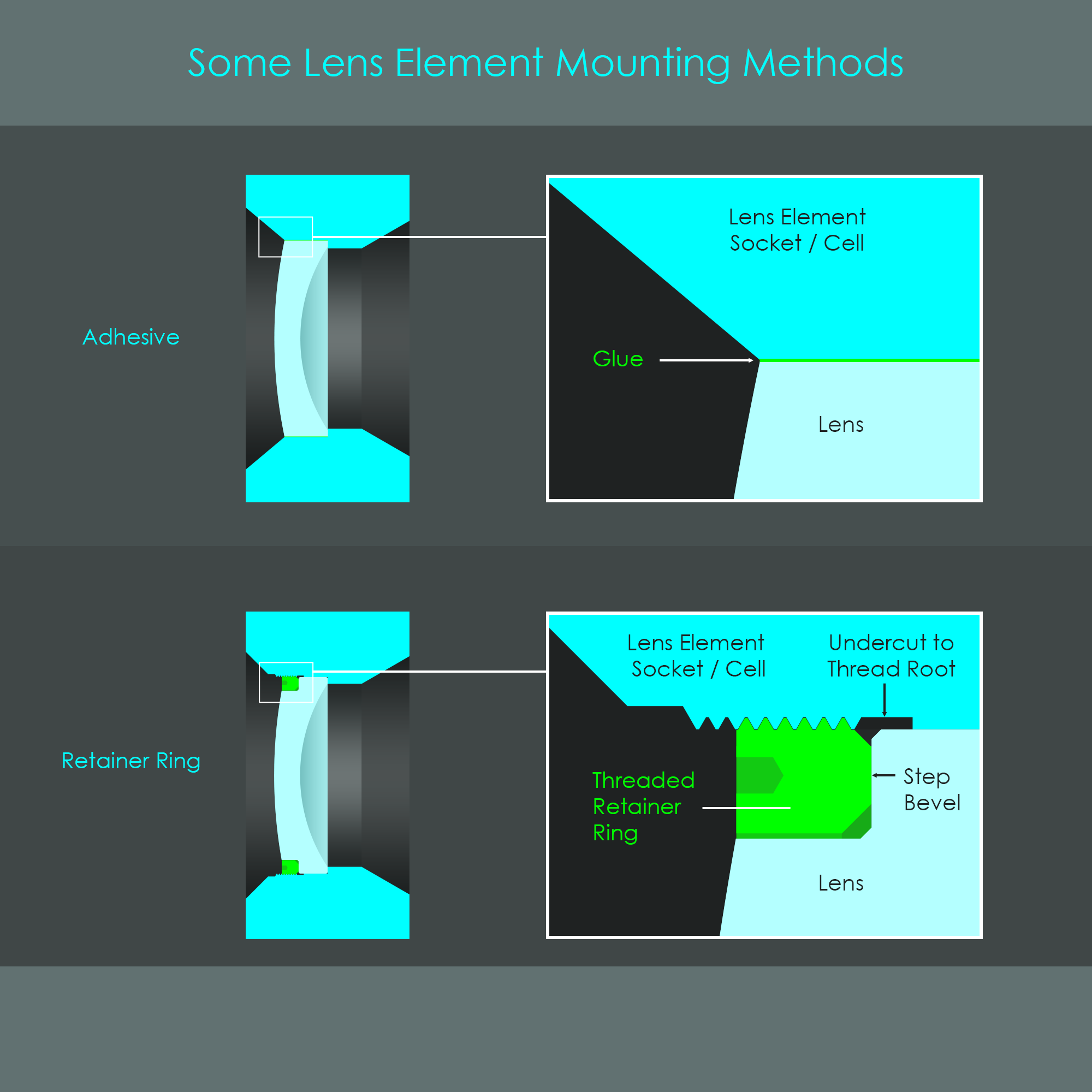
3.3 Lens-to-Mount Interface Design
Mounting optical lenses requires careful control of mechanical stress.
Common mounting approaches include:
- retaining rings
- spring clips
- elastomeric mounts
- flexure mounts
These techniques maintain alignment while preventing stress that could distort the lens surface.
3.4 Mounting of Other Optical Components
Besides lenses, many systems contain:
- mirrors
- prisms
- beam splitters
- sensors
- laser emitters
Each component requires mounting methods that minimize:
- deformation
- thermal stress
- vibration sensitivity
For example, mirrors in high-precision systems may use kinematic mounts that constrain motion while avoiding over-constraint.
3.5 Design for Manufacturing and Assembly
A successful design must consider production from the beginning.
Important factors include:
- machining feasibility
- alignment accessibility
- assembly sequence
- cleaning procedures
Designing self-aligning features significantly reduces assembly errors and calibration time.
4. Collaborative Optomechanical Development Process
Modern optical systems are rarely developed sequentially. Instead, they follow a collaborative and iterative workflow involving:
- optical engineers
- mechanical engineers
- manufacturing specialists
- system integration teams
Early collaboration helps avoid problems such as:
- insufficient mechanical clearance
- unrealistic tolerance requirements
- thermal instability
The design process usually involves multiple iterations:
- Optical design optimization
- Mechanical integration
- Simulation and analysis
- Prototype testing
- Design refinement
This integrated workflow ensures the final product meets both optical and mechanical performance requirements.
5. Thermal Effects in Optical Assemblies
Temperature variations are one of the most significant challenges in optomechanical systems.
When materials experience temperature change, they expand or contract according to their coefficient of thermal expansion.
The thermal expansion equation is:
ΔL = αLΔT
Where:
- α = coefficient of thermal expansion
- L = original length
- ΔT = temperature change
If optical elements and mounts expand at different rates, several issues may occur:
- optical misalignment
- mechanical stress on lenses
- focus drift
Thermal management techniques include:
- heat sinks
- thermal isolation structures
- matched material selection
- controlled ventilation
High-power laser systems and imaging sensors require particularly careful thermal design.
6. Tolerance Analysis in Optical System Integration
Manufacturing imperfections are unavoidable. Every component contains small dimensional variations called tolerances.
Tolerance analysis evaluates how these variations affect optical performance.
Typical tolerance sources include:
- lens decentering
- tilt errors
- spacing deviations
- mechanical machining tolerances
Engineers use Monte Carlo simulations to predict how combined tolerances influence system performance.
A good tolerance strategy balances:
- optical performance
- manufacturing cost
- assembly complexity
Overly strict tolerances dramatically increase production cost, while loose tolerances may degrade performance.
7. Simulation in Optomechanical Engineering
Computer simulation is an essential tool in modern optomechanical design.
Digital models allow engineers to analyze how the system behaves under various conditions before building physical prototypes.
Simulation can evaluate:
- thermal deformation
- vibration response
- mechanical stress
- optical alignment stability
By identifying potential weaknesses early, simulation significantly reduces development time and cost.
8. Finite Element Analysis (FEA) for Structural Validation
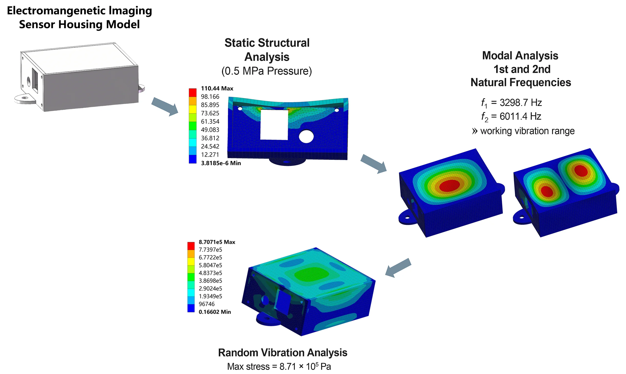
Finite Element Analysis (FEA) is widely used to predict structural behavior.
The model divides the structure into thousands of small elements. The solver calculates how each element responds to forces, temperature, or vibration.
Engineers use FEA to analyze:
- stress distribution
- structural deformation
- thermal expansion effects
- resonance frequencies
For optical systems, even micrometer-scale deformation may degrade performance, making FEA a critical verification tool.
9. Common Engineering Problems in Optomechanical Design
Several recurring challenges appear during optomechanical development.
Misalignment
Small positional errors can introduce optical aberrations or beam deviation.
Thermal Expansion Mismatch
Different materials expanding at different rates can create internal stress.
Vibration Sensitivity
Mechanical resonance may amplify vibration and disturb optical alignment.
Structural Deformation
Weak mechanical supports may bend under load or temperature variation.
Improper Mounting Methods
Incorrect mounting can induce stress in delicate optical elements.
Tolerance Stack-Up
Accumulated manufacturing variations can shift the optical axis beyond acceptable limits.
Early simulation and systematic tolerance analysis help mitigate these issues.
10. Future Trends in Optomechanical Systems
Several technological trends are shaping the future of optomechanical engineering.
Miniaturization
Optical devices are becoming smaller while maintaining higher precision. This is particularly important in:
- smartphones
- autonomous vehicles
- wearable devices
Advanced Materials
New materials such as carbon composites and ultra-low expansion ceramics improve thermal stability.
Additive Manufacturing
High-precision 3D printing allows the creation of lightweight and complex optical mounts that were previously impossible to manufacture.
Integrated Photonics
Some traditional optical components are being replaced by integrated photonic circuits, reducing system size and improving robustness.
These innovations are expanding the role of optomechanics in fields such as:
- space telescopes
- lidar sensing
- medical imaging
- quantum optics
11. FAQ
What is optomechanical design?
Optomechanical design is the engineering discipline that integrates optical components with mechanical structures to maintain alignment, stability, and environmental protection in optical systems.
Why is thermal expansion important in optical systems?
Temperature changes cause materials to expand or contract. If optical elements and mounts expand differently, the resulting movement can degrade optical alignment and image quality.
What materials are commonly used in optomechanical structures?
Common materials include aluminum, stainless steel, titanium, and Invar. Each material is selected based on strength, weight, and thermal expansion characteristics.
What is the role of FEA in optomechanical design?
Finite Element Analysis predicts how structures respond to forces, temperature changes, and vibration, allowing engineers to identify deformation and stress before manufacturing.
Where are optomechanical systems used?
Optomechanical systems are widely used in cameras, telescopes, laser equipment, lidar sensors, medical imaging devices, and aerospace instruments.
12. Conclusion
Optomechanical design plays a critical role in transforming theoretical optical systems into reliable physical products. By integrating optical precision with mechanical stability, engineers ensure that sensitive optical components maintain alignment under real-world conditions.
Successful designs require careful attention to material selection, thermal behavior, tolerance management, and structural stiffness. Advanced simulation tools such as finite element analysis further improve reliability by predicting performance before manufacturing.
As optical technologies continue to evolve, optomechanical engineering will remain essential for building compact, stable, and high-performance optical systems.