


RF Design Engineering Guide: The Technology Behind Modern Wireless Communication
Radio Frequency (RF) engineering forms the foundation of modern wireless communication systems. From smartphones and Wi-Fi routers to satellite networks and radar systems, RF circuits enable reliable transmission of information through electromagnetic waves.
Unlike low-frequency analog circuits, RF systems operate at extremely high frequencies where signal behavior becomes strongly influenced by electromagnetic propagation, impedance matching, transmission line effects, and interference.
This article explains RF design from an engineering perspective, including RF circuit operation, system architecture, filtering techniques, PCB layout constraints, common design challenges, and emerging trends such as 5G and software-defined radio. The goal is to provide a deeper technical understanding of how RF systems are designed and optimized for performance, stability, and reliability.
Table of Contents
- 1. Fundamentals of Radio Frequency (RF)
- 2. Core Principles of RF Circuit Design
- 3. Architecture of Radio Frequency Systems
- 4. RF Filtering Technologies
- 5. Engineering Challenges in RF Design
- 6. Applications of RF Technology
- 7. RF Design vs Conventional Analog Design
- 8. Future Trends in RF Engineering
- 9. FAQ
- 10. Conclusion
1. Fundamentals of Radio Frequency (RF)
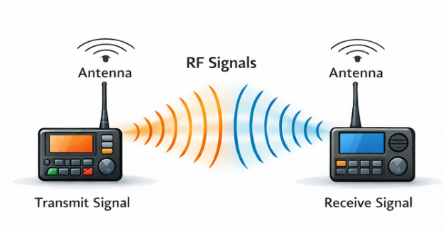
Radio Frequency refers to electromagnetic signals typically ranging from 3 kHz to 300 GHz. These signals propagate through space and allow information to be transmitted without physical wiring.
RF communication works by converting electrical signals into electromagnetic waves using an antenna. These waves travel through free space and are captured by another antenna, which converts them back into electrical signals for processing.
RF communication systems rely on three fundamental processes:
- Signal generation
- Signal modulation
- Signal transmission and reception
Unlike baseband signals, RF signals experience propagation effects such as:
- Path loss
- Multipath fading
- Atmospheric absorption
- Electromagnetic interference
These phenomena make RF design significantly more complex than standard low-frequency circuit design.
2. Core Principles of RF Circuit Design
Designing RF circuits requires understanding both circuit theory and electromagnetic behavior. At high frequencies, even small PCB traces behave like transmission lines.
2.1 Impedance Matching
Most RF systems use a 50-ohm impedance standard. If impedance is mismatched between stages, part of the signal is reflected instead of transmitted.
Key goals of impedance matching:
- maximize power transfer
- minimize reflection
- maintain signal integrity
Common techniques include:
- L-networks
- π networks
- stub matching
- transformer matching
Reflection in RF systems is often evaluated using Voltage Standing Wave Ratio (VSWR) or S-parameters.
2.2 Signal Gain and Noise Control
RF systems require amplification while maintaining a low noise level.
Important amplifier parameters include:
- Gain
- Noise Figure (NF)
- Linearity
- Stability
A Low Noise Amplifier (LNA) is typically used at the receiver front end to amplify weak incoming signals without significantly increasing noise.
2.3 Transmission Line Effects
At frequencies above several hundred MHz, PCB traces behave like transmission lines rather than simple conductors.
Important characteristics include:
- characteristic impedance
- propagation delay
- signal reflection
- dielectric losses
Microstrip and stripline routing techniques are commonly used in RF PCB design.
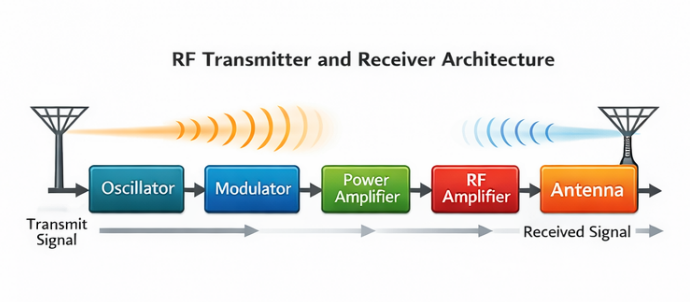
3. Architecture of Radio Frequency Systems
A complete RF communication system consists of several functional blocks that generate, process, and receive RF signals.
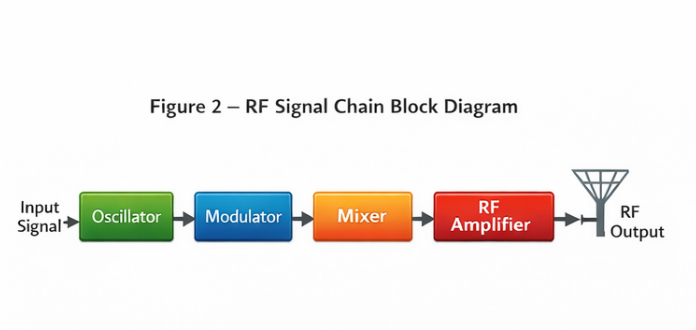
3.1 RF Transmitter Chain
The transmitter prepares and broadcasts the signal.
Typical stages include:
- Oscillator
- Modulator
- Mixer
- RF Power Amplifier
- Antenna
The oscillator generates a carrier frequency, while the modulator embeds information onto that carrier using techniques such as:
- AM (Amplitude Modulation)
- FM (Frequency Modulation)
- QAM (Quadrature Amplitude Modulation)
3.2 RF Receiver Chain
The receiver performs the reverse process.
Typical stages:
- Antenna
- RF filter
- Low Noise Amplifier
- Mixer
- Intermediate Frequency (IF) processing
- Demodulator
The mixer converts the RF signal into a lower intermediate frequency to simplify signal processing.
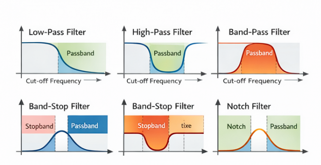
4. RF Filtering Technologies
Filters are essential in RF systems because they control the frequency spectrum and remove interference.
4.1 Low-Pass Filters (LPF)
Low-pass filters allow signals below a cutoff frequency to pass while attenuating higher frequencies.
Typical applications:
- removing harmonic distortion
- smoothing digital switching noise
4.2 High-Pass Filters (HPF)
High-pass filters allow signals above a cutoff frequency to pass.
They are commonly used to remove:
- DC components
- low-frequency interference
4.3 Band-Pass Filters (BPF)
Band-pass filters are widely used in wireless communication because they isolate a specific communication channel.
Example:
A Wi-Fi receiver may use a band-pass filter centered around 2.4 GHz.
4.4 Notch and Band-Stop Filters
Notch filters suppress narrow interference sources such as:
- switching regulators
- local oscillators
- nearby transmitters
Modern RF systems often use SAW (Surface Acoustic Wave) or BAW (Bulk Acoustic Wave) filters for compact high-frequency filtering.
5. Engineering Challenges in RF Design
RF engineering presents several unique challenges that require careful design and simulation.
| Engineering Problem | Technical Explanation | Typical Solution |
|---|---|---|
| Signal Attenuation | High frequency signals lose power through cable loss, PCB dielectric loss, and free-space propagation. | Use low-loss substrates, impedance matching networks, and optimized antenna design. |
| Electromagnetic Interference | External RF sources and digital electronics introduce unwanted signals. | Apply shielding, filtering, and proper PCB grounding. |
| Impedance Mismatch | Mismatched impedances cause signal reflections and power loss. | Design matching networks and maintain controlled impedance traces. |
| Signal Noise | Thermal noise and amplifier noise reduce receiver sensitivity. | Use low-noise amplifiers and optimized gain distribution. |
| Poor PCB Layout | Improper routing causes radiation, coupling, and signal instability. | Short RF traces, ground planes, and isolation between analog and digital sections. |
| Thermal Stress | Power amplifiers generate significant heat. | Heat sinks, thermal vias, and copper planes. |
6. Applications of RF Technology
RF engineering supports a wide range of modern technologies.
6.1 Wireless Communication
Technologies such as:
- cellular networks
- Wi-Fi
- Bluetooth
- satellite internet
all depend on RF front-end design.
6.2 Radar and Sensing Systems
Radar systems transmit RF signals and measure reflections to determine distance, speed, or object location.
Applications include:
- air traffic control
- weather monitoring
- automotive radar
- military detection systems
6.3 Internet of Things (IoT)
Low-power RF protocols such as:
- LoRa
- Zigbee
- NB-IoT
enable billions of connected devices.
7. RF Design vs Conventional Analog Design
| Aspect | RF Design | Traditional Analog Design |
|---|---|---|
| Frequency Range | MHz to GHz | Hz to MHz |
| Signal Behavior | Wave propagation and transmission line effects dominate | Mostly lumped circuit behavior |
| PCB Sensitivity | Extremely sensitive to trace geometry and layout | Less sensitive |
| Design Tools | Electromagnetic simulation and S-parameter analysis | SPICE-based circuit simulation |
| Complexity | Higher due to impedance matching and interference | Relatively simpler |
8. Future Trends in RF Engineering
Several technological shifts are shaping the future of RF design.
5G and Millimeter Wave Communication
5G systems operate in frequency bands above 24 GHz, introducing new challenges in:
- antenna arrays
- beamforming
- propagation loss
RF Front-End Integration
Modern smartphones integrate multiple RF components into compact RF front-end modules (FEMs) to reduce size and power consumption.
Software Defined Radio (SDR)
SDR systems implement modulation and signal processing in software rather than hardware, allowing flexible communication protocols.
Advanced Antenna Technologies
Emerging innovations include:
- phased array antennas
- MIMO systems
- metamaterial antennas
These technologies dramatically improve wireless throughput and coverage.
9. FAQ
Why is impedance matching important in RF circuits?
Impedance mismatch causes signal reflections, reducing power transfer and degrading signal quality. Proper matching ensures maximum energy delivery between stages.
Why are RF PCB layouts more sensitive than analog circuits?
At high frequencies, PCB traces behave like transmission lines. Even millimeter-level changes can alter impedance and cause signal reflections or radiation.
What is the role of a mixer in RF systems?
A mixer shifts a signal from one frequency to another by combining it with a local oscillator signal. This process simplifies filtering and signal processing.
Why do RF circuits require specialized components?
High-frequency signals require components with precise parasitic characteristics, low loss, and stable performance across wide frequency ranges.
10. Conclusion
RF engineering is a specialized discipline that bridges circuit design and electromagnetic theory. Successful RF systems depend on careful control of impedance, signal amplification, filtering, and PCB layout.
As wireless technologies continue to evolve—driven by 5G, IoT, and satellite networks—the importance of advanced RF design will only increase. Engineers must combine theoretical knowledge with practical design techniques to create reliable, high-performance wireless communication systems.