


Three-Point Starter Explained: Design Principles, Protection Logic, and Practical Engineering Considerations
In DC motor systems, startup is the most electrically stressful operating condition. At standstill, back electromotive force (back EMF) is zero, while the armature resistance is extremely low. If rated voltage is applied directly, inrush current may rise to several times the rated current—leading to commutator damage, overheating, and mechanical shock.
The Three-Point Starter was developed to control this condition in a simple and reliable manner. Although modern drives frequently use electronic controllers, this starter remains fundamental in classical DC motor control and continues to be used in workshops, laboratories, and legacy industrial systems.
This article provides a structured engineering analysis of its working principle, protection logic, advantages, limitations, and maintenance considerations.
Table of Contents
- Introduction to Three-Point Starters
- Why DC Motors Require Controlled Starting
- Working Principle of a Three-Point Starter
- Protection Mechanisms: No-Volt and Overload Release
- Main Components and Their Engineering Roles
- Advantages of a Three-Point Starter
- Applications in Industrial and Educational Systems
- Three-Point vs Four-Point Starter
- Limitations and Design Constraints
- Maintenance and Reliability Best Practices
- Frequently Asked Questions (FAQ)
- Conclusion
Introduction to Three-Point Starters
A Three-Point Starter is a manually operated starting device designed specifically for DC motors. The name derives from its three external terminals:
- L (Line) – Power supply input
- A (Armature) – Armature circuit connection
- F (Field) – Field winding connection
Its core functions include:
- Limiting starting current
- Providing under-voltage (no-volt) protection
- Providing overload protection
From a systems engineering perspective, it is both a current control mechanism and a safety device.
Why DC Motors Require Controlled Starting
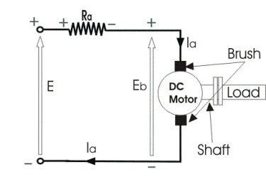
Armature current in a DC motor is governed by:
[ I_a = \frac{V - E_b}{R_a} ]
Where:
- (V) = Supply voltage
- (E_b) = Back EMF
- (R_a) = Armature resistance
At startup:
- Rotor speed = 0
- Back EMF (E_b) = 0
- Armature resistance is very small
Therefore, without external resistance, the starting current would be excessive. The Three-Point Starter inserts series resistance to limit current and gradually removes it as the motor accelerates and back EMF develops.
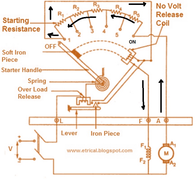
Working Principle of a Three-Point Starter
Initial Position (OFF)
.jpg)
The starter handle rests at OFF. The motor is disconnected from the power supply.
First Contact – Maximum Resistance
When the handle is moved to the first contact point:
- Full external resistance is placed in series with the armature
- Starting current is limited to a safe value
Acceleration Phase
As motor speed increases:
- Back EMF rises
- Armature current decreases
- External resistance is gradually reduced step-by-step
Normal Running Position
When the handle reaches the final contact:
- All external resistance is removed
- The motor operates under rated conditions
Protection Mechanisms: No-Volt and Overload Release
No-Volt Coil (NVC)
- Connected in series with the field winding
- Holds the starter handle in the RUN position
- If supply voltage fails, magnetic force collapses
- The spring returns the handle to OFF
This prevents automatic restarting when power is restored.
Overload Release (OLR)
- Installed in the armature circuit
- Trips when current exceeds a preset limit
- Disconnects the motor to prevent thermal damage
Main Components and Their Engineering Roles
Starting Resistance
- Wire-wound or cast iron resistor sections
- Designed for short-duration thermal loading
- Divided into multiple steps
Starter Handle and Contact Studs
- Mechanical sliding arm
- Sequential contact engagement
- Requires low contact resistance
No-Volt Coil
- Electromagnetic holding device
- Dependent on field current
Overload Release Mechanism
- Calibrated current-sensitive device
- Protects against sustained overload
Advantages of a Three-Point Starter
- Effective control of inrush current
- Built-in under-voltage protection
- Integrated overload protection
- Simple mechanical construction
- Low installation and maintenance cost
- High durability in industrial environments
Applications in Industrial and Educational Systems
Three-Point Starters are commonly used in:
- Machine tools such as lathes and drilling machines
- DC cranes and hoists
- Small conveyor systems
- Educational laboratory motor test setups
- Legacy DC elevator installations
While electronic drives are common in modern installations, mechanical starters remain practical in low-complexity systems.
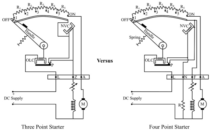
Three-Point vs Four-Point Starter
The fundamental difference lies in the no-volt coil connection.
In a Three-Point Starter:
- The NVC is connected in series with the field winding.
If field current is reduced for speed control (field weakening), the magnetic holding force decreases, potentially causing unintended tripping.
In a Four-Point Starter:
- The no-volt coil is connected directly across the supply.
This makes it more suitable for applications requiring wide-range speed control.
Limitations and Design Constraints
- Manual operation only
- Not suitable for frequent start-stop cycles
- Limited compatibility with advanced speed control
- Applicable only to DC motors
- Provides basic protection compared to modern motor drives
Maintenance and Reliability Best Practices
Contact Inspection
- Check for pitting, burning, or carbon deposits
- Ensure proper contact pressure
Resistance Bank Inspection
- Inspect for cracks or overheating
- Verify continuity
No-Volt Coil Testing
- Confirm proper holding force
- Check field circuit continuity
Terminal Tightening
Loose terminals may cause arcing and localized heating.
Overload Calibration
Ensure overload release trips at the intended current rating.
Preventive maintenance significantly improves long-term reliability.
Frequently Asked Questions (FAQ)
1. Why is a Three-Point Starter required for DC motors?
Because DC motors draw very high current at startup due to zero back EMF. The starter limits this current and prevents damage.
2. Can a Three-Point Starter be used for AC motors?
No. It is designed specifically for DC motors and cannot be used for AC motor systems.
3. What happens if the supply voltage fails during operation?
The no-volt coil de-energizes, releasing the handle to OFF and preventing automatic restart.
4. Why is it called a Three-Point Starter?
It has three terminals: Line (L), Armature (A), and Field (F).
5. What is the main disadvantage compared to a Four-Point Starter?
The no-volt coil is connected in series with the field winding, making it unsuitable for wide-range field-weakening speed control.
6. Is a Three-Point Starter still used today?
Yes, particularly in educational setups, legacy systems, and small DC motor installations where simplicity and cost-effectiveness are priorities.
Conclusion
The Three-Point Starter is a classical yet technically sound solution for controlling DC motor startup. By combining staged resistance control with integrated protective mechanisms, it ensures safe and reliable operation.
Although modern electronic drives provide greater flexibility and automation, the Three-Point Starter remains relevant in applications where robustness, simplicity, and cost efficiency are key considerations.
Understanding its design and operating logic is essential for engineers maintaining traditional DC motor systems or selecting appropriate starting methods.