


Voltage Divider: Engineering Principles, Design Equations and Practical Applications
A voltage divider is one of the most fundamental circuits in electronics, used to convert a higher voltage into a lower and usable level. Despite its simple structure, correct voltage divider design requires understanding resistor ratios, load effects, current consumption, and power dissipation. These factors determine whether the circuit will operate accurately and reliably.
This article explains the engineering principles behind voltage dividers, derives the key formulas used in circuit analysis, and explores practical design considerations. It also discusses common mistakes, real-world applications, and how voltage dividers compare with voltage regulators in electronic systems.
Table of Contents
- 1. What Is a Voltage Divider
- 2. Fundamental Operating Principle
- 3. Basic Voltage Divider Circuit Structure
- 4. Mathematical Derivation of the Voltage Divider Equation
- 5. Practical Voltage Divider Design Process
- 6. Load Effect and Output Accuracy
- 7. Engineering Applications of Voltage Dividers
- 8. Voltage Divider vs Voltage Regulator
- 9. Advantages and Limitations
- 10. FAQ
- 11. Conclusion
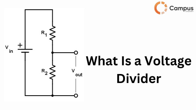
1. What Is a Voltage Divider
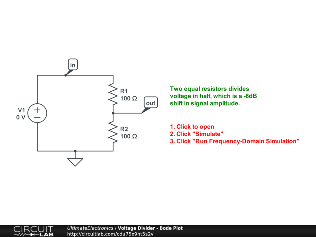
A voltage divider is a passive linear circuit that produces a fraction of its input voltage as output. It typically consists of two resistors connected in series across a voltage source, where the output voltage is taken from the junction between the resistors.
The principle behind the voltage divider is based on Ohm’s Law and series circuit behavior, where the voltage drop across each resistor is proportional to its resistance.
Voltage dividers are widely used in:
- Sensor signal conditioning
- Reference voltage generation
- Analog signal scaling
- ADC input protection
- Battery monitoring circuits
Although the circuit is simple, improper design can lead to inaccurate output voltages or excessive power consumption.
2. Fundamental Operating Principle
In a series circuit, the same current flows through every component. When two resistors are connected in series across a voltage source, the total voltage is distributed across them based on their resistance values.
The resistor with the larger resistance will drop a larger portion of the total voltage.
This proportional distribution forms the basis of voltage division.
Voltage divider formula:
Vout = Vin × (R2 / (R1 + R2))
Where:
- Vin = input voltage
- R1 = upper resistor
- R2 = lower resistor
- Vout = voltage measured across R2
3. Basic Voltage Divider Circuit Structure
A standard voltage divider consists of four essential elements.
Input Voltage Source
The input voltage provides the electrical potential that will be divided. Examples include:
- Power supply rails
- Battery sources
- Sensor outputs
Series Resistors
Two resistors determine the voltage ratio. Their relationship defines the output voltage level.
Typical design ranges:
- 1kΩ – 100kΩ for analog circuits
- 10kΩ – 1MΩ for low-power systems
Output Node
The midpoint between resistors provides the scaled voltage.
This node may feed into:
- Analog-to-Digital Converters (ADC)
- Comparator inputs
- Amplifier stages
Ground Reference
The lower resistor connects to ground, which defines the reference potential for measuring the output voltage.
4. Mathematical Derivation of the Voltage Divider Equation
The voltage divider equation can be derived directly from Ohm’s Law.
Ohm’s Law:
V = I × R
First calculate the current through the series circuit.
I = Vin / (R1 + R2)
The output voltage across R2 is then:
Vout = I × R2
Substituting current gives:
Vout = Vin × (R2 / (R1 + R2))
This equation shows that only the resistor ratio determines the output voltage.
Voltage Across Each Resistor
Upper resistor:
VR1 = Vin × (R1 / (R1 + R2))
Lower resistor:
VR2 = Vin × (R2 / (R1 + R2))
The sum satisfies Kirchhoff’s Voltage Law:
VR1 + VR2 = Vin
5. Practical Voltage Divider Design Process
Designing a voltage divider requires more than choosing random resistor values.
A practical design process includes the following steps.
Step 1 — Define Input and Target Output Voltage
Example:
Vin = 12V
Vout = 3.3V
Step 2 — Calculate Resistor Ratio
R2 / (R1 + R2) = 3.3 / 12
This gives the ratio needed for the resistor pair.
Step 3 — Choose Practical Resistor Values
Example:
R1 = 27kΩ
R2 = 10kΩ
These produce an output close to 3.3V.
Step 4 — Verify Current Consumption
Divider current:
I = Vin / (R1 + R2)
Engineers typically design the divider current to be:
- 10× larger than ADC input leakage
- 10× larger than load current
This minimizes measurement error.
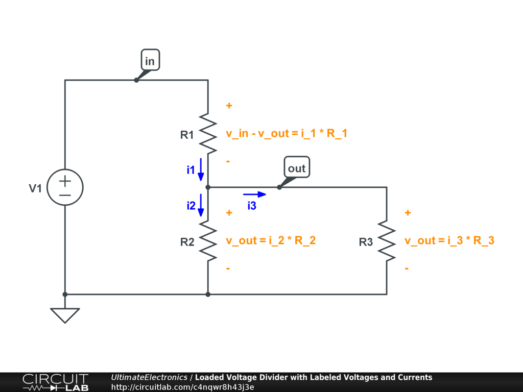
6. Load Effect and Output Accuracy
In real circuits, the output node usually connects to another circuit. This introduces a load resistance (RL).
The load effectively forms a parallel resistor with R2, changing the output voltage.
Effective resistance becomes:
Req = (R2 × RL) / (R2 + RL)
The new output voltage is then:
Vout = Vin × (Req / (R1 + Req))
If RL is not significantly larger than R2, the voltage will drop below the intended value.
Engineering rule:
RL ≥ 10 × R2
This keeps voltage error below approximately 10%.
7. Engineering Applications of Voltage Dividers
Voltage dividers appear in almost every analog and mixed-signal system.
Sensor Signal Conditioning
Many sensors produce higher voltages than microcontrollers can accept. Voltage dividers scale signals safely for ADC inputs.
Examples:
- Thermistors
- Light sensors
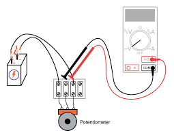
- Potentiometers
Reference Voltage Generation
Voltage dividers generate reference voltages used in:
- Comparator circuits
- Analog bias networks
- Operational amplifier thresholds
Battery Voltage Measurement
Microcontrollers typically accept 3.3V or 5V inputs.
Voltage dividers allow safe measurement of:
- 12V batteries
- Lithium battery packs
- Automotive power rails
Analog Audio Circuits
Voltage dividers are used for:
- Signal attenuation
- Biasing amplifier stages
- Impedance matching
8. Voltage Divider vs Voltage Regulator
| Feature | Voltage Divider | Voltage Regulator |
|---|---|---|
| Principle | Passive resistor ratio | Active voltage regulation |
| Output Stability | Changes with load | Maintains constant voltage |
| Efficiency | Low for high current | Higher efficiency |
| Circuit Complexity | Very simple | More complex |
| Typical Use | Signal scaling | Power supply regulation |
A voltage divider should not be used to power devices requiring stable current, such as microcontrollers or digital logic circuits.
9. Advantages and Limitations
Advantages
- Extremely simple circuit design
- Very low component cost
- Easy to calculate output voltage
- Useful for signal conditioning and voltage references
Limitations
- Output voltage changes with load
- Continuous power dissipation
- Not suitable for high current loads
- Limited voltage accuracy without buffering
For stable outputs, engineers often combine voltage dividers with operational amplifier buffers or voltage regulators.
10. FAQ
Why does the output voltage change when a load is connected?
Because the load forms a parallel resistance with R2, altering the resistor ratio and reducing the output voltage.
What resistor values are typically used?
Common ranges:
1kΩ – 100kΩ
Higher values reduce power consumption but increase sensitivity to electrical noise.
Can a voltage divider power a microcontroller?
No. A voltage divider should not be used as a power supply because the output voltage varies with current draw.
How can voltage divider accuracy be improved?
Methods include:
- Using precision resistors (1% or 0.1%)
- Increasing divider current
- Adding an operational amplifier buffer
- Minimizing load current
11. Conclusion
Voltage dividers are among the most fundamental circuits in electronics, enabling engineers to scale voltages, create references, and interface sensors with digital systems. While the concept is straightforward, practical implementations must account for load effects, current consumption, and resistor tolerances.
Understanding these engineering considerations ensures voltage divider circuits operate reliably in real-world electronic designs.