


What Are Gears? Engineering Principles, Types, Design Parameters and Installation Guide
Gears are fundamental power transmission elements used to precisely control torque, speed, and motion direction in mechanical systems. Compared with belt and chain drives, gears provide non-slip transmission, high efficiency, and compact design, making them indispensable in automotive, robotics, industrial machinery, and precision equipment.
This article delivers an engineering-level analysis of gear design, including involute tooth theory, load behavior, material selection, failure mechanisms, and installation best practices.
Table of Contents
- 1. Gear Fundamentals and Working Principle
- 2. Gear Geometry and Design Parameters
- 3. Types of Gears and Engineering Characteristics
- 4. Materials and Heat Treatment
- 5. Gear Performance and Failure Mechanisms
- 6. Industrial Applications
- 7. Gear Selection Methodology
- 8. Gear vs Belt vs Chain Drive
- 9. Gear Installation and Alignment Engineering
- 10. Conclusion
- FAQ
1. Gear Fundamentals and Working Principle
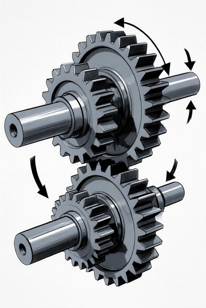
A gear is a toothed rotating machine element that transmits mechanical power between shafts through meshing teeth. Unlike friction-based drives, gears use positive engagement, ensuring zero slip and precise motion transfer.
Key Concepts
-
Gear Ratio (i)
i = Z₂ / Z₁ -
Torque-Speed Relationship
Smaller gears rotate faster with lower torque, while larger gears rotate slower with higher torque. -
Direction Control
External gears reverse rotation; internal gears maintain direction. -
Motion Conversion
Rack and pinion systems convert rotational motion into linear motion.
2. Gear Geometry and Design Parameters
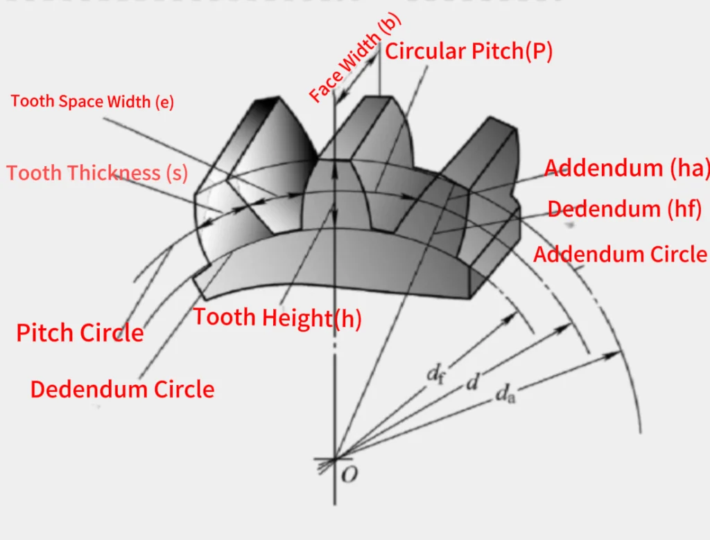
Gear performance is primarily determined by tooth geometry and dimensional accuracy.
Key Parameters
- Module (m)
- Pressure Angle (typically 20°)
- Pitch Circle
- Addendum and Dedendum
- Backlash
Engineering Insight
The involute tooth profile ensures constant velocity ratio and tolerance to minor misalignment, making it the industry standard.
Contact Mechanics
Gear tooth interaction involves:
- Rolling + sliding motion
- Hertzian contact stress
- Load distribution across contact ratio
3. Types of Gears and Engineering Characteristics
Different gear types are selected based on shaft orientation, load, and application requirements.
Main Types
- Spur Gear: Parallel shafts, simple design, high efficiency
- Helical Gear: Angled teeth, smooth and quiet operation, generates axial force
- Bevel Gear: Used for intersecting shafts, typically 90°
- Worm Gear: High reduction ratio, self-locking capability
- Planetary Gear: Compact, high torque density, load sharing
- Rack and Pinion: Converts rotary motion into linear movement
4. Materials and Heat Treatment
Gear material selection directly impacts durability, strength, and wear resistance.
| Material | Characteristics | Typical Applications |
|---|---|---|
| Alloy Steel | High strength, fatigue resistant | Automotive, heavy machinery |
| Cast Iron | Good damping, low cost | Industrial equipment |
| Bronze | Low friction, anti-seizure | Worm gears |
| Engineering Plastics | Lightweight, low noise | Consumer electronics |
| Aluminum | Lightweight, corrosion resistant | Light-duty systems |
Heat Treatment Methods
- Carburizing
- Nitriding
- Induction Hardening
5. Gear Performance and Failure Mechanisms
Performance Factors
- Load and stress distribution
- Lubrication condition
- Temperature
- Surface roughness
Common Failure Modes
- Pitting (surface fatigue)
- Scuffing (adhesive wear)
- Tooth bending fatigue
- Plastic deformation
Engineering Insight
Most failures originate from contact fatigue and lubrication breakdown, not immediate overload.
6. Industrial Applications
Gears are widely used across engineering systems:
- Automotive transmissions and differentials
- Industrial gearboxes and conveyors
- Robotics and automation systems
- Aerospace actuation systems
- Consumer electronics devices
7. Gear Selection Methodology
Selection Steps
- Define torque and load requirements
- Determine required speed ratio
- Select gear type based on shaft layout
- Evaluate available installation space
- Choose material and heat treatment
- Consider lubrication and maintenance
Design Considerations
- Safety factor (1.5–3 typical)
- Efficiency vs noise trade-off
- Manufacturing process (hobbing, grinding)
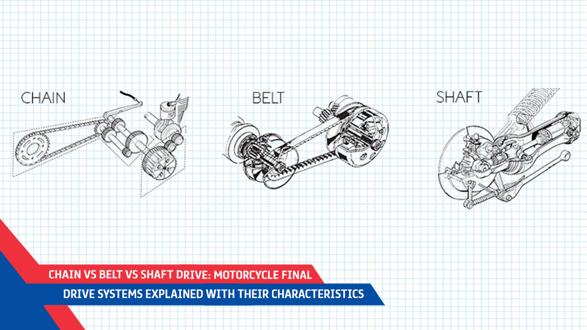
8. Gear vs Belt vs Chain Drive
| Feature | Gear Drive | Belt Drive | Chain Drive |
|---|---|---|---|
| Slip | No slip | Possible | No slip |
| Efficiency | Very high | Medium | High |
| Noise | Medium–High | Low | Medium |
| Maintenance | Medium | Low | Medium |
| Load Capacity | High | Low–Medium | Medium–High |
| Distance | Short | Long | Medium |
9. Gear Installation and Alignment Engineering
Mounting Methods
- Key and keyway
- Spline shaft
- Press fit (interference fit)
- Set screw locking
Alignment Requirements
- Parallelism control
- Shaft runout minimization
- Tooth contact pattern verification
Backlash Adjustment
- Too small → overheating and wear
- Too large → vibration and noise
Best Practices
- Apply correct lubrication
- Use proper torque specifications
- Perform no-load testing after installation
10. Conclusion
Gears remain one of the most reliable and efficient mechanical transmission solutions. Their performance depends on proper design, material selection, lubrication, and installation accuracy. A systematic engineering approach ensures long service life and optimal performance.
FAQ
Q1: Why are involute gears widely used?
Because they maintain a constant velocity ratio and tolerate minor alignment errors.
Q2: What is the main cause of gear failure?
Surface fatigue (pitting) due to repeated contact stress.
Q3: How do you calculate gear ratio?
Divide the number of teeth of the driven gear by the driver gear.
Q4: Which gear is best for high torque?
Planetary and worm gears are commonly used due to high load capacity.
Q5: How often should gears be lubricated?
Typically every 500–2000 operating hours depending on load and environment.