


What Is a MAP Sensor in a Car and How It Works: An Engineering Perspective
The Manifold Absolute Pressure (MAP) sensor is a critical component in modern engine management systems, enabling precise estimation of engine load by measuring intake manifold pressure. This article provides a detailed engineering-level explanation of its working principle, electrical characteristics, system integration, and diagnostic methods.
Table of Contents
- 1. Introduction to MAP Sensors
- 2. Operating Principle and Signal Conversion
- 3. Sensor Types and Measurement Models
- 4. Installation Location and System Integration
- 5. Electrical Interface and Signal Characteristics
- 6. Role in Engine Control Algorithms
- 7. Failure Modes and Diagnostics
- 8. Maintenance and Calibration
- 9. FAQ
- 10. Conclusion
1. Introduction to MAP Sensors
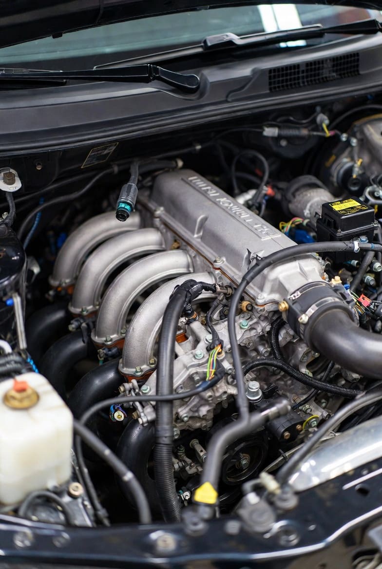
Image Name: map-sensor-intake-manifold-location.jpg
Alt Text: MAP sensor mounted on intake manifold in a car engine
The MAP sensor measures absolute pressure inside the intake manifold, which directly reflects engine load. It is widely used in speed-density engine management systems to estimate air intake without requiring a mass airflow sensor.
2. Operating Principle and Signal Conversion
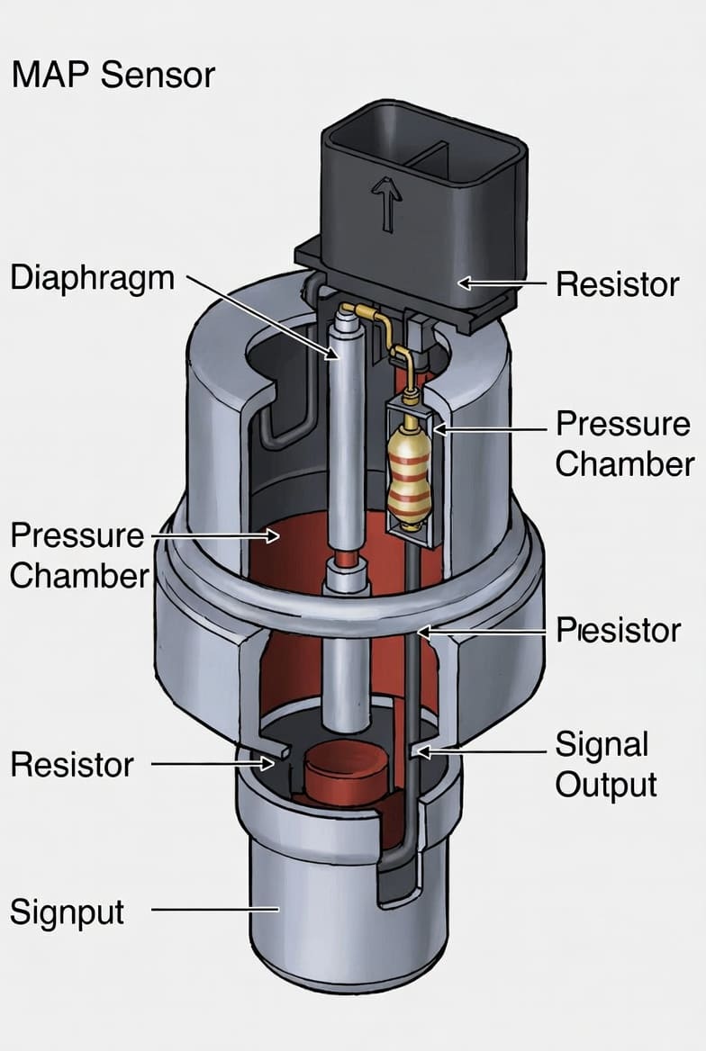
Image Name: map-sensor-internal-structure-diagram.png
Alt Text: internal structure of MAP sensor showing MEMS pressure diaphragm
2.1 MEMS Pressure Sensing Element
MAP sensors use a silicon diaphragm with piezoresistive elements. Pressure changes cause deformation, which alters resistance and produces a voltage signal.
2.2 Signal Conditioning
The signal is amplified, temperature compensated, and converted into a stable analog output (typically 0.5V–4.5V), suitable for ECU processing.
2.3 Pressure-to-Voltage Behavior
| Engine State | Pressure Level | Voltage Output |
|---|---|---|
| Idle (High Vacuum) | Low | ~0.8–1.5V |
| Medium Load | Medium | ~2–3V |
| Wide Open Throttle | High | ~4–4.5V |
3. Sensor Types and Measurement Models
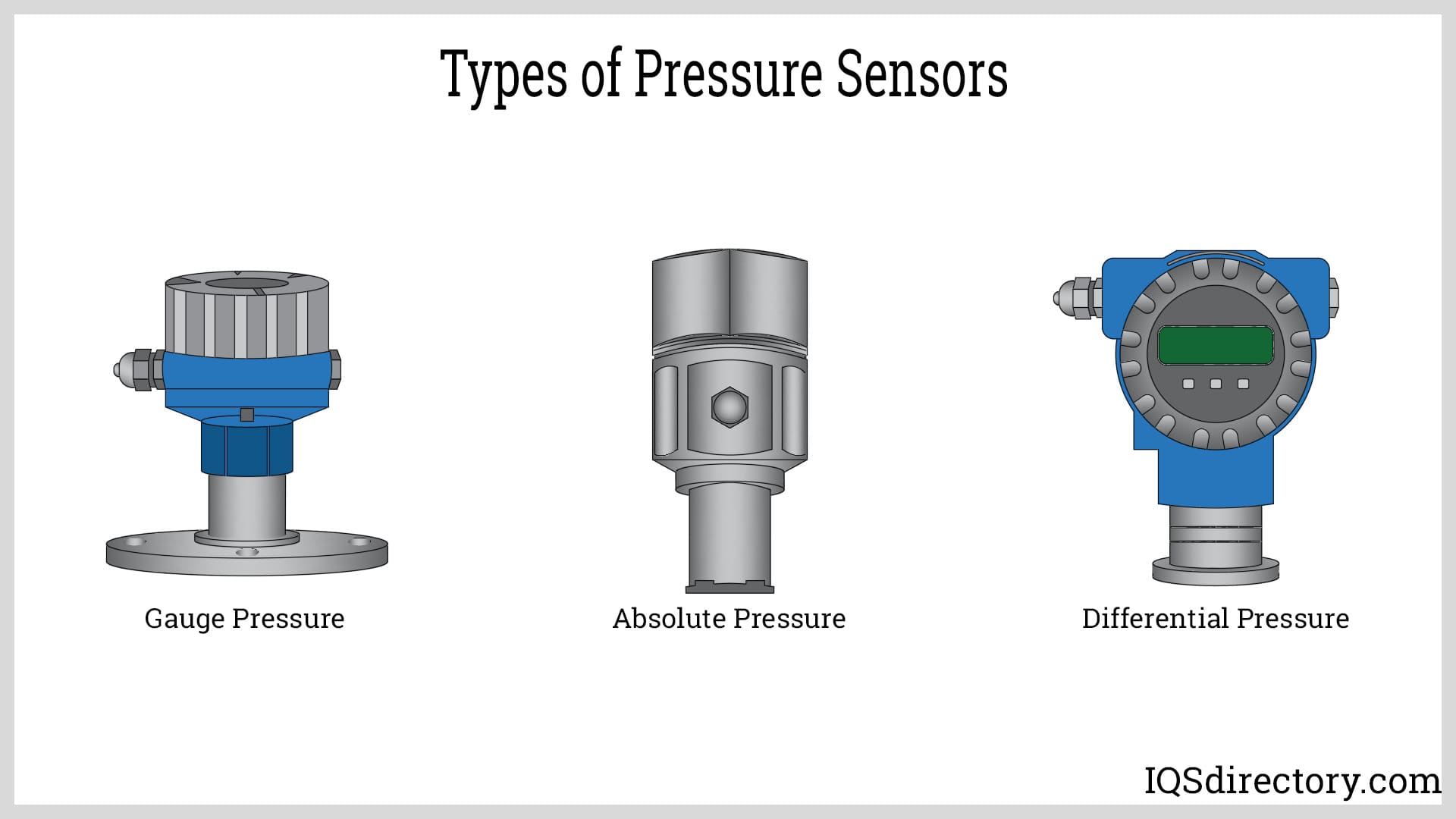
Image Name: pressure-sensor-types-absolute-gauge-differential.png
Alt Text: comparison of absolute, gauge, and differential pressure sensors
3.1 Absolute Pressure Sensors
These sensors measure pressure relative to a perfect vacuum and are the standard type used in MAP applications.
3.2 Gauge Pressure Sensors
Gauge sensors measure pressure relative to ambient atmospheric pressure and are commonly used in tire pressure monitoring.
3.3 Differential Pressure Sensors
These sensors measure the pressure difference between two points and are often used in EGR and filtration systems.
4. Installation Location and System Integration
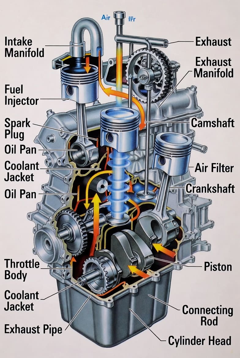
Image Name: map-sensor-engine-placement-diagram.png
Alt Text: diagram showing MAP sensor location in engine intake system
MAP sensors are typically mounted directly on the intake manifold or connected via a vacuum hose. Placement is critical for accurate and responsive readings.
Engineering Considerations
- Minimize pressure signal delay
- Avoid high-temperature zones
- Ensure mechanical stability under vibration
5. Electrical Interface and Signal Characteristics
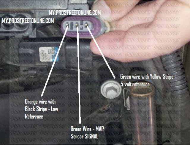
Image Name: map-sensor-wiring-diagram-3-pin.png
Alt Text: MAP sensor 3 pin wiring diagram showing VCC signal and ground
5.1 Pin Configuration
| Pin | Function | Description |
|---|---|---|
| VCC | Power Supply | 5V reference from ECU |
| GND | Ground | Electrical reference |
| OUT | Signal Output | Analog voltage proportional to pressure |
5.2 Signal Characteristics
- Linear analog output
- Fast response time
- Requires ECU filtering for noise suppression
6. Role in Engine Control Algorithms
The MAP sensor is fundamental in speed-density-based engine control systems.
It allows the ECU to estimate intake air mass using pressure, temperature, and engine parameters, enabling:
- Accurate fuel injection
- Optimized ignition timing
- Efficient combustion
7. Failure Modes and Diagnostics
Common Failure Modes
- Contamination from oil or carbon
- Electrical connection faults
- Sensor aging or drift
- Intake vacuum leaks
Typical Symptoms
- Rough idle
- Engine hesitation
- Increased fuel consumption
- Check engine light activation
Diagnostic Approach
- Verify 5V supply
- Measure signal voltage
- Compare readings with expected pressure values
8. Maintenance and Calibration
Cleaning Procedure
Use a non-residue electronic cleaner and avoid touching the sensing element. Allow full drying before reinstalling.
Calibration Notes
MAP sensors are factory calibrated. Replacement may require ECU adaptation depending on vehicle design.
9. FAQ
Q1: What is the difference between MAP and MAF sensors?
MAP sensors estimate airflow indirectly using pressure, while MAF sensors measure airflow directly.
Q2: Can a faulty MAP sensor damage the engine?
Yes. Incorrect air-fuel ratios can lead to knocking, overheating, and long-term engine wear.
Q3: What happens if the MAP sensor fails?
The ECU switches to a default operating mode, reducing performance and efficiency.
Q4: How often should a MAP sensor be cleaned?
Typically every 30,000–50,000 km depending on operating conditions.
10. Conclusion
The MAP sensor is a core component in modern engine management systems, providing essential data for load calculation and combustion control. Its accurate operation directly impacts engine efficiency, emissions, and drivability. Proper understanding, maintenance, and diagnostics of the MAP sensor are essential for ensuring optimal engine performance.