


What Is a MAP Sensor in a Car and How It Works
Modern automotive engines rely on multiple sensors for precise control, and the Manifold Absolute Pressure (MAP) Sensor is one of the most critical components. It measures the absolute pressure in the intake manifold and sends this data to the Engine Control Unit (ECU) to regulate the air-fuel mixture and ignition timing. This article provides a technical deep dive into the MAP sensor, including its working principle, types, location, wiring, maintenance, and common issues.
Table of Contents
- What is a MAP Sensor?
- Working Principle of a MAP Sensor
- Types of MAP Sensors
- MAP Sensor Location and Mounting
- MAP Sensor Wiring and Pinout
- Importance of MAP Sensor in Engine Control
- Applications of MAP Sensors
- Common Issues and Solutions
- Maintenance: Cleaning and Testing
- FAQ
- Conclusion
What is a MAP Sensor?
The MAP Sensor is a critical pressure sensor installed in automotive engines to measure the air pressure inside the intake manifold. The ECU uses this information to calculate the engine load and determine the optimal fuel injection and ignition timing for efficient combustion.
MAP sensors not only optimize engine power output but also improve fuel economy and reduce exhaust emissions. In modern closed-loop engine management systems, precise pressure measurements are essential, making the MAP sensor a core component.
%20Sensor.jpg)
Figure 1: Manifold Absolute Pressure (MAP) Sensor
Working Principle of a MAP Sensor
The MAP Sensor Internal Structure converts intake manifold pressure variations into an electrical voltage signal using a silicon or metallic diaphragm.
Intake manifold pressure fluctuates with engine speed and throttle opening.
The pressure-sensitive diaphragm bends in response to pressure changes.
Internal electronics convert the mechanical deformation into a voltage output sent to the ECU.
For example, when the driver presses the accelerator, manifold pressure increases. The MAP sensor detects this change and transmits the new signal to the ECU, which adjusts fuel injection to maintain power and smooth engine operation.
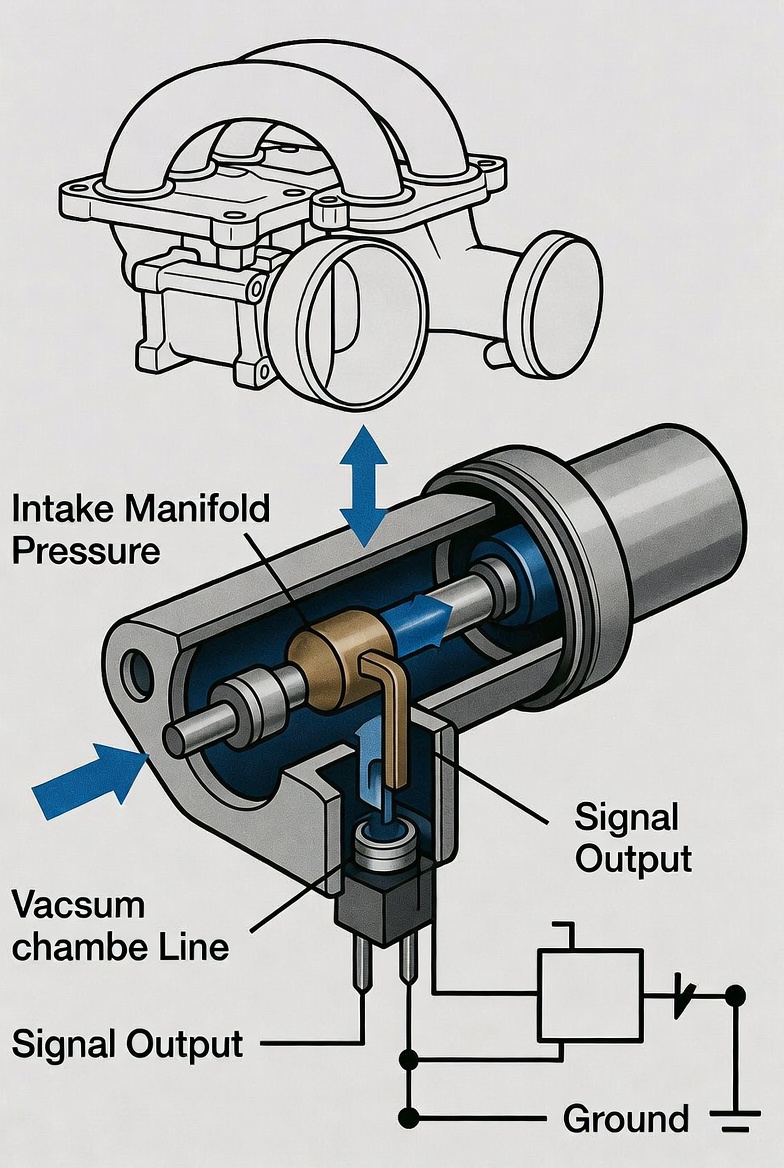
Figure 2: Internal structure and working principle of a MAP sensor
Types of MAP Sensors
Absolute Pressure Sensors
Measure pressure relative to a perfect vacuum. The sensor output is unaffected by atmospheric pressure variations, making it ideal for engine management. Most automotive MAP sensors are absolute pressure types.
Gauge Pressure Sensors
Measure pressure relative to ambient atmospheric pressure. Common in tire pressure monitoring and fluid systems. Less frequently used in engine intake systems.
Differential Pressure Sensors
Measure the pressure difference between two points. Used to monitor components such as air filters or exhaust systems to detect blockages or leaks affecting performance or emissions.
MAP Sensor Location and Mounting
MAP Sensor Location is typically mounted on or near the intake manifold to directly sense pressure.
-
Usually attached with screws or bolts on the manifold or throttle body.
-
Some designs connect via a vacuum tube to the sensor mounted elsewhere.
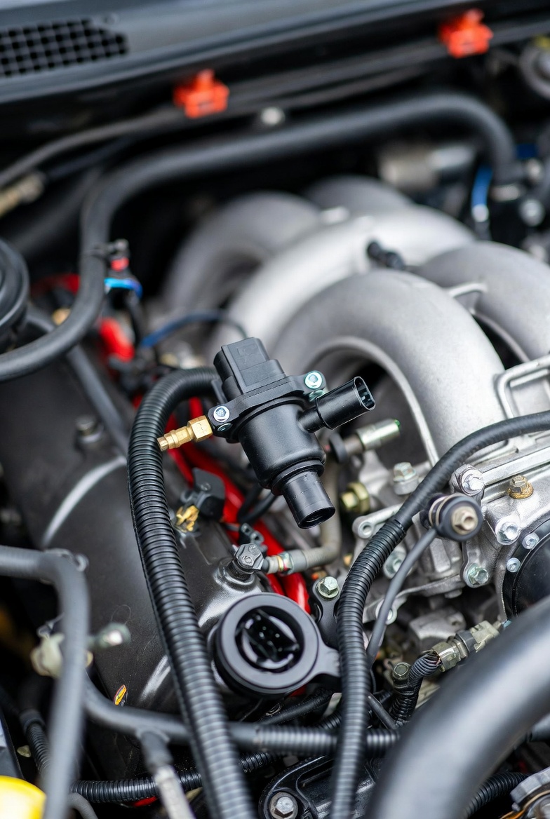
Figure 3: Typical MAP sensor installation in the engine bay
MAP Sensor Wiring and Pinout
Most MAP sensors have a three-pin connector:
| Pin | Function |
|---|---|
| VC | 5V reference from ECU |
| PIM | Signal output voltage proportional to manifold pressure |
| E2 | Ground for stable reference |
The internal pressure element converts manifold pressure variations into a voltage signal sent to the ECU for precise fuel injection and ignition control.
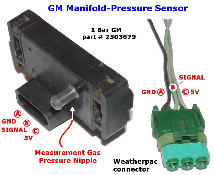
Figure 4: MAP sensor pinout and wiring diagram
Importance of MAP Sensor in Engine Control
MAP sensors provide ECU with engine load data for optimal operation. Key functions:
-
Accurate air-fuel ratio control for efficient combustion.
-
Real-time load monitoring for power optimization and fuel economy.
-
Emission reduction by ensuring complete fuel combustion.
-
Monitoring turbocharged engines for safe and efficient operation.
Applications of MAP Sensors
-
Engine control systems
-
Fuel injection optimization
-
Engine load monitoring
-
Emission control
-
Turbocharger intake pressure monitoring
Common Issues and Solutions
-
Contamination: Oil or carbon deposits cause inaccurate readings → clean sensor.
-
Electrical issues: Loose or damaged wiring → inspect connections.
-
Vacuum leaks: Hose or intake leak → repair or replace.
-
Signal faults: Internal sensor failure → replacement needed.
Maintenance: Cleaning and Testing
Cleaning Steps
Turn off the engine and disconnect the battery.
Remove the MAP sensor from its mounting.
Spray the sensing element with a MAP or electronic cleaner.
Allow the sensor to air dry completely and reinstall.
Testing with a Multimeter
-
Measure voltage between VC and ground (~5V).
-
Measure voltage between signal and ground; voltage should change with manifold pressure.
-
Constant or abnormal readings indicate sensor malfunction or need for cleaning/replacement.
FAQ
Q1: What is the difference between MAP and MAF sensors? MAP measures manifold pressure; MAF measures airflow. Both inform ECU air-fuel calculations but operate differently.
Q2: How can I tell if a MAP sensor is failing? Symptoms include rough idle, reduced power, increased fuel consumption, and illuminated check engine light.
Q3: Can cleaning extend the life of a MAP sensor? Cleaning removes contamination but does not repair damaged electronics.
Q4: Is MAP sensor replacement difficult? Most sensors are easy to replace; ensure power is disconnected and handle the sensor element carefully.
Conclusion
The MAP Sensor is essential for modern engine management. By accurately monitoring intake manifold pressure, it allows the ECU to precisely control fuel injection and ignition timing. Proper understanding, maintenance, and testing ensure engine efficiency, performance, and emission compliance.