


What Is USB? An Engineer’s View of the World’s Most Successful Interface (1996–2026)
Universal Serial Bus (USB) began as a practical solution to interface fragmentation. Nearly three decades later, it has evolved into a high-bandwidth, high-power system interconnect capable of transporting storage, display, PCIe, and up to 240 W of power through a single reversible connector.
In 2026, USB is not simply a peripheral interface—it is a layered architecture integrating protocol management, device abstraction, signal integrity engineering, and negotiated power delivery.
Table of Contents
- 1. USB as a Host-Centric Architecture
- 2. Hardware Topology and Electrical Design
- 3. Evolution of USB Standards (1996–2026)
- 4. USB Connector Types: From Legacy to Type-C
- 5. Frequently Asked Questions (FAQ)
- 6. Conclusion
1. USB as a Host-Centric Architecture
USB is fundamentally host-controlled. Devices never arbitrate the bus; the host controller schedules and initiates every transaction. This design eliminates bus contention and enables deterministic bandwidth allocation.
Layered Software Structure
USB can be understood in three logical layers:
1) Host Controller Layer
Modern systems use xHCI controllers that unify USB 2.0 and USB 3.x handling. Responsibilities include:
- Transfer scheduling
- Event management
- Endpoint queue handling
- Power-state coordination
2) USB Core Stack
The OS-level stack manages:
- Device enumeration
- Descriptor parsing
- Address assignment
- Bandwidth allocation
- Suspend/resume transitions
USB communication is structured around endpoints and pipes, supporting four transfer types:
- Control
- Bulk
- Interrupt
- Isochronous
3) Client Drivers
Class drivers (HID, Mass Storage, UVC, CDC, etc.) abstract hardware behavior from applications. This layered separation is one of USB’s most resilient architectural decisions.
2. Hardware Topology and Electrical Design
USB uses a tiered star topology. A single host connects to multiple downstream devices through hubs, supporting up to 127 logical devices per controller.
Core Structural Elements
Host (Root Hub)
Integrated into the chipset or controller card. It:
- Issues token packets
- Assigns device addresses
- Controls port power
- Manages bus timing
Hubs
Active repeaters that:
- Detect connect/disconnect events
- Provide per-port power switching
- Perform multi-speed transaction translation
Functions (Devices)
Each USB device typically integrates:
- PHY layer
- Serial Interface Engine (SIE)
- Endpoint controller
- Descriptor storage
In embedded systems, descriptor configuration largely determines device identity and interoperability.
Signaling Evolution
- USB 2.0 — Half-duplex signaling over D+/D−
- USB 3.x — Adds SuperSpeed TX/RX pairs (full duplex)
- USB Type-C — Introduces CC lines for:
- Role detection
- Cable identification
- Power negotiation
Power Delivery (USB PD 3.1 EPR)
Modern USB Type-C supports:
- Up to 48 V
- Up to 5 A
- Up to 240 W
This enables single-cable docking for high-performance laptops and workstations.
3. Evolution of USB Standards (1996–2026)
Early Generations
- USB 1.1 — 12 Mb/s
- USB 2.0 — 480 Mb/s
USB 2.0 remains widely deployed in embedded and industrial systems due to low implementation cost and sufficient throughput for control-oriented peripherals.
SuperSpeed Era (USB 3.x)
- USB 3.2 Gen 1 — 5 Gbps
- USB 3.2 Gen 2 — 10 Gbps
- USB 3.2 Gen 2×2 — 20 Gbps
Enhancements included:
- Full-duplex architecture
- More efficient encoding schemes
- Improved power management
USB4 and USB4 Version 2.0
USB4 introduced protocol tunneling:
- PCIe
- DisplayPort
- USB 3.x
High-end implementations now support:
- Up to 80 Gbps symmetric
- Up to 120 Gbps asymmetric
USB4 standardizes exclusively on USB Type-C.
4. USB Connector Types: From Legacy to Type-C
USB Type-A
The traditional host-side connector for decades.
Limitations:
- Non-reversible
- Limited power scaling
- No alternate mode support
Still common in desktops and industrial systems.
Mini-B
Mini-B appeared in early portable electronics such as digital cameras and MP3 players. It offered better durability than the original Type-B but is bulky by modern standards and effectively obsolete today.
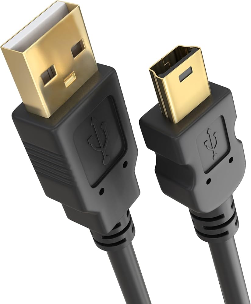
Figure 1 — USB Mini-B plug and receptacle design
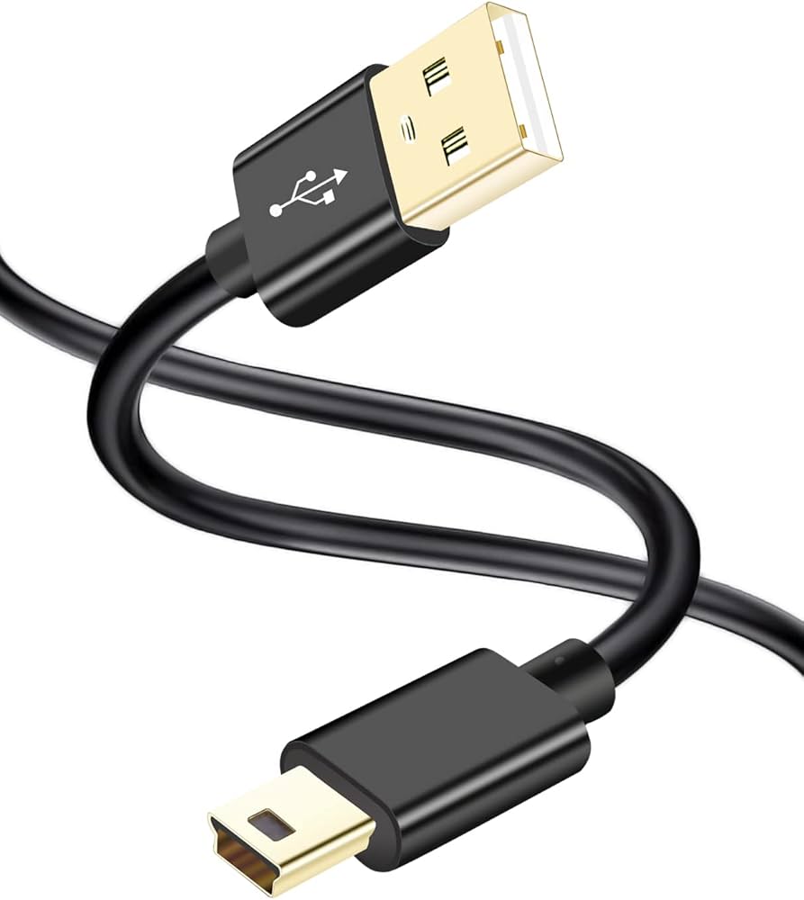
Figure 2 — Mini-B cable assembly
.jpg)
Figure 3 — Mini-B pinout reference (VBUS, D−, D+, ID, GND)
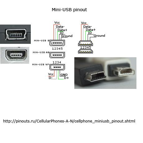
Figure 4 — Mini-B SMD receptacle footprint
Micro-USB
Micro-USB replaced Mini-B in smartphones and compact devices due to smaller size and improved mechanical rating. It is now largely phased out in favor of Type-C.
USB Type-C
USB Type-C represents the modern unified interface:
- 24-pin reversible connector
- Role swapping (DFP/UFP/DRP)
- Integrated Power Delivery
- Alternate Mode capability
- Required connector for USB4
Type-C is the first USB connector designed for long-term electrical scalability and high-power operation.
5. Frequently Asked Questions (FAQ)
1. Is USB4 the same as Thunderbolt?
USB4 incorporates Thunderbolt protocol foundations, but certification requirements and guaranteed feature sets differ.
2. Why do some USB-C cables not support full speed or 240 W?
Cable capability depends on:
- Number of SuperSpeed lanes
- Presence of e-marker chip
- Current rating (3 A vs 5 A)
Full 240 W operation requires 5 A EPR-rated cables.
3. Why is USB 2.0 still common?
Its PHY is simpler, cheaper, and consumes less power. For low-bandwidth peripherals, higher-speed standards offer no practical benefit.
4. Can USB replace HDMI or PCIe?
In USB4 systems, those protocols are tunneled through USB transport. Functionally yes—but architecturally they remain encapsulated protocols.
5. Is USB Type-A obsolete?
Not entirely. While consumer devices are shifting to Type-C, legacy and industrial platforms still rely heavily on Type-A.
6. Conclusion
USB’s long-term dominance rests on three core engineering principles:
- Host-controlled scheduling
- Layered abstraction of protocol and hardware
- Strict backward compatibility
In 2026, USB is no longer a peripheral convenience—it is foundational infrastructure for power delivery, display transport, storage, and high-speed interconnect.
The connector may appear simple. The architecture behind it is not.