AC Adapter Selection Guide: How to Choose the Right Power Supply for Your Application
Selecting the appropriate AC adapter for your electronic device requires careful consideration of multiple technical parameters, safety certifications, and application-specific requirements. This comprehensive guide walks you through the critical specifications, performance trade-offs, and design considerations that engineering teams face when specifying AC adapters for consumer electronics, industrial equipment, medical devices, and IoT applications.
Table of Contents
- What is an AC Adapter and Why Selection Matters
- Key Technical Parameters Explained
- How to Choose the Right AC Adapter for Your Application
- Performance Comparison by Application Type
- Design Considerations and Common Pitfalls
- Safety Certifications and Compliance Requirements
- FAQ
- Conclusion and Recommended Next Steps
1. What is an AC Adapter and Why Selection Matters
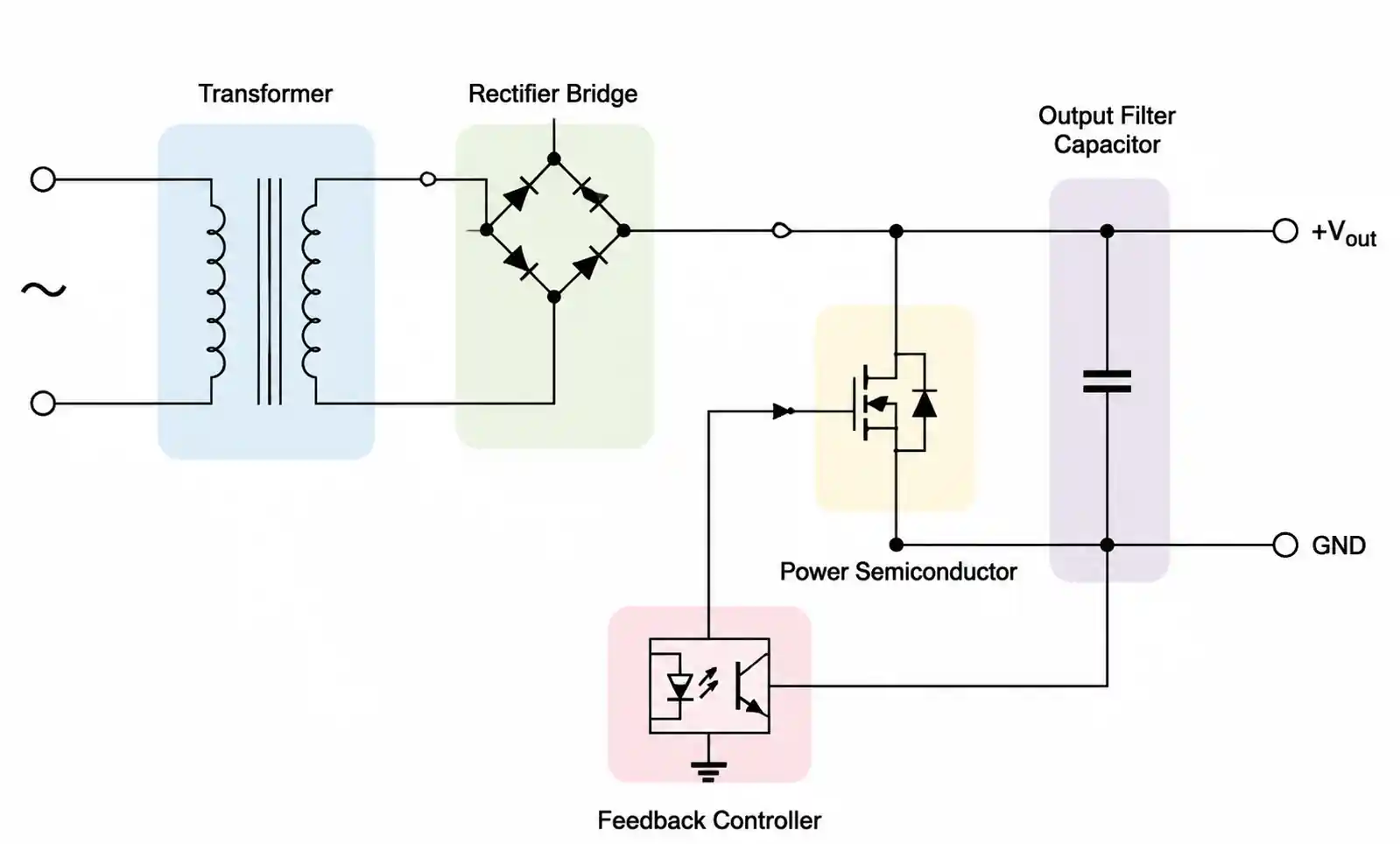
An AC adapter, also known as a power supply or wall adapter, converts alternating current (AC) from the mains supply into direct current (DC) suitable for powering electronic devices. While this function appears straightforward, improper adapter selection can lead to device malfunction, reduced product lifespan, safety hazards, or regulatory compliance failures.
The selection process becomes critical when you consider that modern electronic devices demand increasingly tight voltage regulation, low electromagnetic interference (EMI), high efficiency for energy compliance, and robust protection circuitry. Engineers must balance performance requirements against cost constraints, physical size limitations, and global certification needs.
This guide focuses on helping design engineers, procurement teams, and product managers make informed decisions during the adapter selection phase, rather than discovering specification mismatches during final testing or after product launch.
2. Key Technical Parameters Explained
Understanding the technical parameters listed in an AC adapter datasheet is essential for proper component selection. These specifications directly impact system reliability, efficiency, and regulatory compliance.
Output Voltage and Regulation
The output voltage rating must match your device's input requirement within acceptable tolerance. Most electronic devices specify a nominal voltage (e.g., 12V, 19V, 24V) with an acceptable range, typically ±5% to ±10%. Look for adapters with tight load regulation (typically ≤3%) and line regulation (typically ≤1%) to ensure stable operation across varying load conditions and input voltage fluctuations.
When the adapter operates at light load or no load, some designs exhibit higher output voltage due to reduced internal voltage drop. Verify that this no-load voltage remains within your device's absolute maximum rating to prevent damage during hot-plug scenarios.
Current Rating and Power Capacity
The adapter's current rating must exceed your device's maximum continuous current draw with adequate margin. A common engineering practice is to specify an adapter rated for 120-150% of the device's maximum current to account for inrush current, component aging, and thermal derating.
Pay attention to whether the datasheet specifies continuous current or peak current ratings. Some lower-cost adapters rate their output for intermittent duty cycles rather than continuous operation, which can lead to thermal shutdown in real-world applications.
Efficiency and No-Load Power Consumption
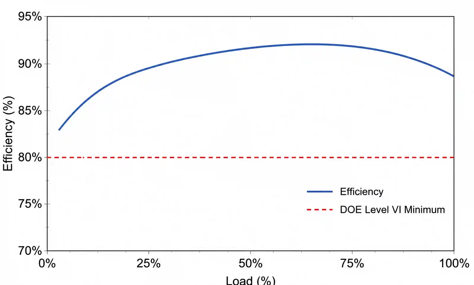
Efficiency ratings directly impact operating cost, thermal management requirements, and compliance with energy regulations such as DOE Level VI, EU CoC Tier 2, and Energy Star. Modern switching adapters typically achieve 85-92% efficiency at rated load, with Level VI requiring minimum average efficiency of 86% for adapters rated 1-49W and 88% for 49-250W.
No-load power consumption has become increasingly regulated, with Level VI limiting standby power to 0.1W for adapters rated up to 49W and 0.21W for higher power ratings. Verify that your selected adapter meets the efficiency requirements for all target markets, as non-compliance can prevent product sales in regulated regions.
Ripple and Noise Specifications
Output ripple (periodic AC component superimposed on DC output) and noise (high-frequency switching artifacts) can interfere with sensitive analog circuitry, communication interfaces, and RF sections. Typical specifications range from 50-150mV peak-to-peak for general-purpose adapters, while precision applications may require <30mV.
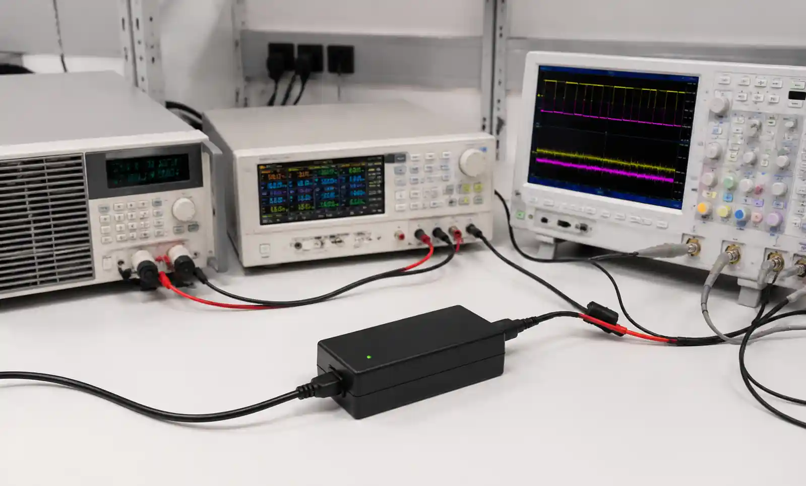
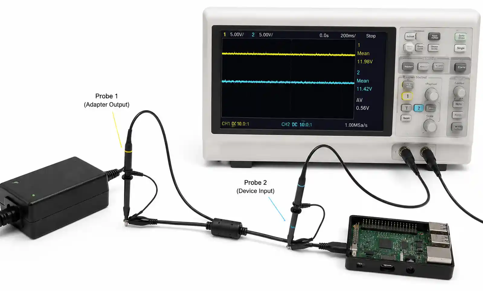
When reviewing datasheets, note the measurement bandwidth and method. Some manufacturers specify ripple measured with a 20MHz bandwidth limitation, while others use full-bandwidth measurements that capture high-frequency noise components. For applications sensitive to switching noise, request oscilloscope plots showing actual output waveforms under load.
Protection Features
Modern AC adapters incorporate multiple protection circuits to enhance reliability and safety. Essential protections include over-voltage protection (OVP), over-current protection (OCP), over-temperature protection (OTP), and short-circuit protection (SCP). Verify that protection thresholds align with your device's tolerance limits.
Pay particular attention to OVP behavior. Some designs latch off and require power cycling, while others auto-recover. Latching protection prevents repeated stress on downstream components but may reduce system availability. Auto-recovery suits applications where temporary overloads are acceptable and quick restart is prioritized.
3. How to Choose the Right AC Adapter for Your Application
Systematic adapter selection involves matching technical requirements with application constraints while maintaining adequate safety margins and cost targets.
Step 1: Define Your Electrical Requirements
Start by documenting your device's precise electrical needs. Measure or calculate the maximum continuous current draw, peak inrush current, acceptable voltage range, and required ripple limits. Include margin for future feature additions or component tolerance variations.
For devices with multiple operating modes, characterize power consumption across all states including startup, active operation, idle, and sleep modes. The adapter must handle the worst-case scenario while maintaining efficiency at typical operating points.
Step 2: Identify Physical and Environmental Constraints
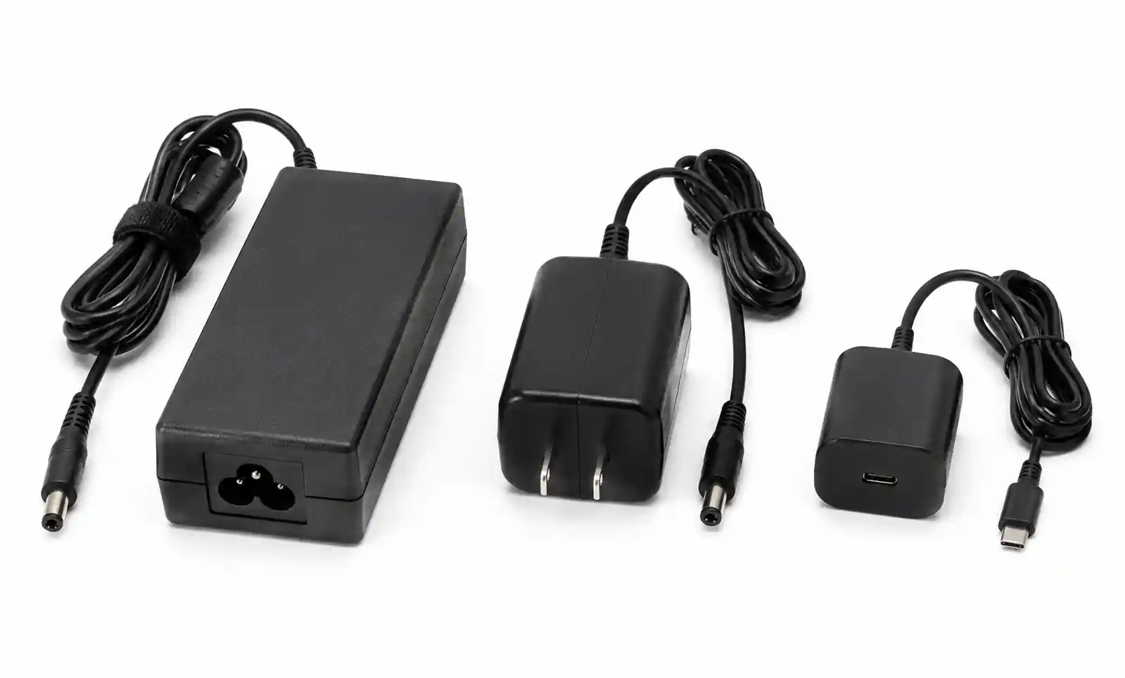
Physical form factor often constrains adapter selection. Desktop adapters offer higher power capacity and better thermal performance but require more space. Wall-mount designs save desk space but face stricter thermal limitations due to reduced airflow and proximity to heat-sensitive surfaces.
Consider the operating environment carefully. Industrial applications may require extended temperature ranges (-40°C to +85°C), while consumer products typically specify 0°C to +40°C. Outdoor installations need IP-rated enclosures for moisture and dust protection. Medical applications demand isolation ratings of 2×MOPP (Means of Patient Protection) and additional leakage current restrictions.
Step 3: Evaluate Connector and Cable Requirements
The output connector type and cable length significantly impact voltage drop and EMI performance. Longer cables increase resistive losses, requiring voltage compensation at the adapter output or selection of heavier gauge wire. For cables exceeding 2 meters, calculate the voltage drop using the wire gauge and maximum current to ensure adequate voltage reaches the device.
Connector selection should consider mechanical durability, polarity protection, and retention force. Barrel connectors remain common but lack robust latching, while locking connectors provide superior connection security for mobile or vibration-prone applications.
Step 4: Match Certification Requirements to Target Markets
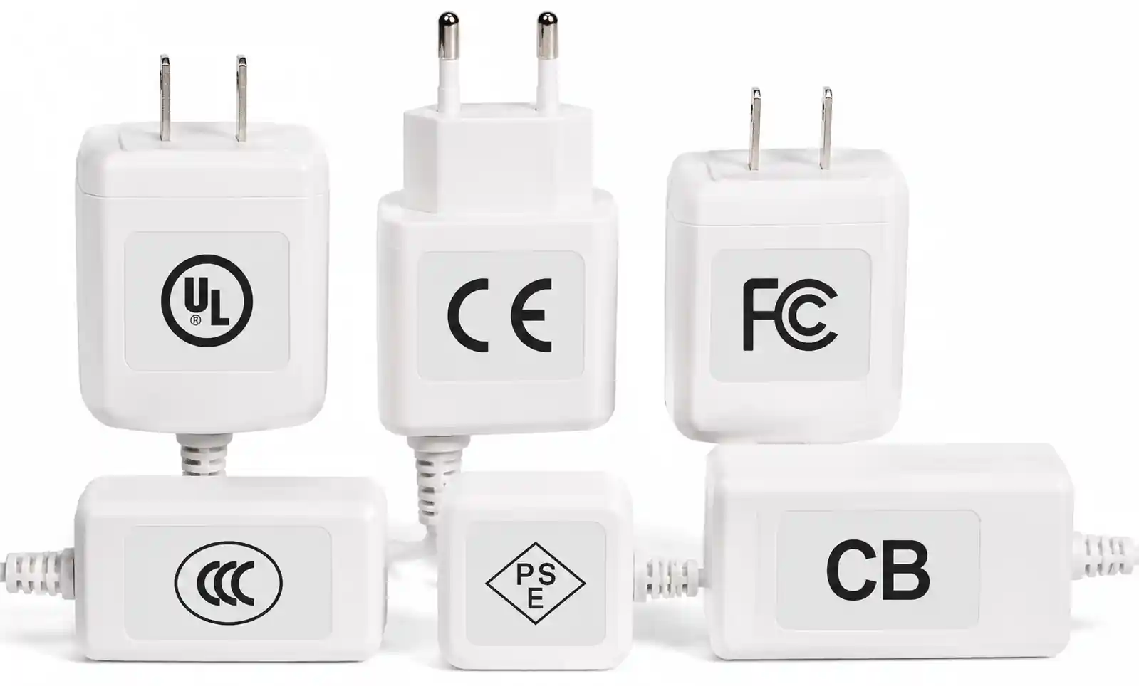
Different markets mandate different safety certifications. North American products typically require UL or ETL listing, European markets require CE marking with LVD and EMC compliance, and many Asian markets accept CB scheme certificates with country-specific deviations. Medical devices need IEC 60601-1 compliance, while information technology equipment follows IEC 60950-1 or the newer IEC 62368-1.
Energy efficiency certifications add another layer. Verify that the adapter meets DOE Level VI for US market, EU CoC Tier 2 for Europe, and any additional regional requirements. Some utilities and government procurement programs require Energy Star certification, which imposes stricter efficiency thresholds than base regulations.
4. Performance Comparison by Application Type
Different applications prioritize different adapter characteristics. This comparison helps identify which specifications matter most for your specific use case.
| Application Type | Key Priority Parameters | Typical Power Range | Critical Certifications | Common Challenges |
|---|---|---|---|---|
| Consumer Electronics | Cost, size, efficiency | 5W - 65W | DOE Level VI, CE, CB | Price pressure, global certification matrix |
| Industrial Automation | Reliability, wide temperature, EMI | 30W - 150W | UL, CE, IEC 61000-6-2 | Harsh environments, electrical noise immunity |
| Medical Devices | Isolation rating, leakage current, MTBF | 10W - 150W | IEC 60601-1, 2×MOPP | Patient safety, stringent documentation requirements |
| IoT and Battery Charging | Efficiency, standby power, form factor | 5W - 30W | DOE Level VI, CE, Energy Star | Minimize standby loss, fast charge support |
| LED Lighting | Constant current, dimming, lifetime | 20W - 100W | UL Class 2, CE, IP rating | Flicker-free operation, outdoor durability |
| Telecom Equipment | Hold-up time, redundancy, -48VDC option | 50W - 400W | TUV, UL, NEBS Level 3 | Input brownout ride-through, parallel operation |
The table above illustrates that no single adapter design optimally serves all applications. Consumer electronics prioritizes cost and compact size, accepting moderate reliability specifications. Industrial applications demand extended temperature ranges and robust EMI performance, justifying higher component costs. Medical devices require exhaustive documentation and multiple redundant safety features, significantly increasing development and certification expenses.
When evaluating adapters for cost-sensitive consumer applications, focus on meeting minimum regulatory requirements while optimizing for manufacturing volume. Industrial and medical applications benefit from selecting adapters with proven field reliability and comprehensive technical support, even at premium pricing.
Performance vs. Cost Trade-offs
Higher efficiency adapters use advanced topologies (LLC resonant, active clamp flyback) and premium components (SiC or GaN semiconductors, low-ESR capacitors) that increase manufacturing cost by 15-40% compared to conventional designs. This investment pays off through reduced operating costs, smaller thermal design requirements, and easier regulatory compliance.
Similarly, adapters with tighter voltage regulation and lower ripple require more sophisticated feedback control and better output filtering, adding cost but improving compatibility with sensitive loads. When your application includes precision analog circuitry, communication interfaces, or RF sections, the incremental adapter cost often proves negligible compared to system-level EMI mitigation costs.
5. Design Considerations and Common Pitfalls
Learning from field experience helps avoid specification errors that lead to costly redesigns or product recalls.
Thermal Management Mistakes
Underestimating thermal requirements represents one of the most common adapter selection errors. Adapters generate heat proportional to power loss (input power minus output power), and this heat must dissipate to ambient without exceeding maximum component temperatures. Wall-mount adapters face particularly challenging thermal conditions when installed on thermally insulated walls or in recessed outlets with restricted airflow.
Always verify the adapter's rated ambient temperature and derating curves. An adapter rated for 100W at 25°C might deliver only 70W at 40°C ambient temperature. When your product specifies operation at elevated ambient temperatures, select an adapter with adequate derating margin or consider forced air cooling.
Input Voltage Range Oversights
Many engineers specify adapters for their home market without considering global deployment requirements. North American products typically operate from 120VAC ±10%, while European markets use 230VAC ±10%. Universal input adapters (90-264VAC) accommodate worldwide use but cost moderately more and exhibit slightly lower efficiency at low input voltage.
Wide input voltage range also affects inrush current and hold-up time. At low input voltage, the adapter draws higher input current, potentially tripping sensitive circuit breakers. At high input voltage, inrush current peaks can reach 50-100A for a few milliseconds, requiring robust input filtering and circuit breaker compatibility.
Cable Voltage Drop Calculations
A frequently overlooked issue involves voltage drop in the DC output cable, particularly for higher current applications. For example, a 3A adapter with 2 meters of 24AWG wire experiences approximately 0.5V drop under full load (24AWG wire has ~84mΩ/meter resistance, so 4 meters total for round-trip yields ~336mΩ, giving V=IR=3A×0.336Ω≈1V drop).
This voltage drop reduces the voltage delivered to your device below the adapter's specified output voltage. Compensate by either specifying a slightly higher adapter output voltage, using heavier gauge wire, or limiting cable length. For precision applications, consider using Kelvin sensing connections that monitor voltage at the load rather than at the adapter output.
Ignoring Transient Response Requirements
Adapters require finite time to respond to sudden load changes. When your device exhibits rapid current steps (e.g., microprocessor entering burst mode, motor startup, RF transmission pulses), the adapter's output voltage temporarily dips or overshoots before regulation recovers. Typical recovery times range from 100μs to several milliseconds depending on adapter design.
If your device's voltage tolerance exceeds what the adapter's transient response provides, you must add local output capacitance near the load. Calculate the required capacitance using ΔV = I×Δt/C, where I is the current step, Δt is the adapter's response time, and ΔV is your allowable voltage deviation.
Connector Mechanical Durability
Consumer products with frequently inserted/removed connectors face wear-related failures after thousands of mating cycles. Standard barrel connectors rate for 5,000-10,000 insertion cycles, while USB connectors specify 10,000 cycles for Type-A and 10,000 cycles for Type-C. When your application involves frequent connection changes, verify that both the adapter connector and mating device connector meet the required cycle life.
Additionally, connector retention force matters for mobile or vibration-prone installations. Loose connectors cause intermittent power loss, voltage fluctuations, and arcing that damages both the connector and device. Specify connectors with positive latching mechanisms for applications exposed to movement or vibration.
6. Safety Certifications and Compliance Requirements
Navigating the global certification landscape requires understanding both mandatory safety requirements and voluntary energy efficiency programs.
Primary Safety Standards
Safety certifications verify that the adapter meets minimum electrical safety requirements including insulation coordination, protective earth continuity, temperature limits, and fault condition behavior. The relevant standard depends on the adapter's end-use application and target market.
For general-purpose adapters used with information technology equipment, IEC 62368-1 has replaced the older IEC 60950-1 standard. This hazard-based safety engineering standard applies to both power supplies and end products, creating a consistent safety framework across the product ecosystem. Medical device adapters must comply with IEC 60601-1 and demonstrate appropriate isolation levels (2×MOPP for patient-connected applications), controlled leakage current (<100μA for Type BF equipment), and comprehensive risk management documentation.
EMC Compliance Considerations
Electromagnetic compatibility certification ensures that the adapter neither emits excessive electromagnetic interference nor exhibits susceptibility to external interference. Conducted emissions (150kHz to 30MHz) and radiated emissions (30MHz to 1GHz) must remain within limits specified by FCC Part 15 Class B (North America), CISPR 32 Class B (international), or equivalent regional standards.
Switching power supplies inherently generate EMI due to fast voltage and current transitions. Proper filter design, PCB layout, and shielding determine whether the adapter meets EMC requirements. When integrating an adapter into your product, remember that system-level EMC testing may reveal issues not present during adapter standalone testing, particularly for conducted emissions coupling through the DC output cable.
Energy Efficiency Mandates
Multiple overlapping energy efficiency regulations affect adapter selection. The US Department of Energy (DOE) Level VI standard, effective since 2016, sets minimum average efficiency requirements and maximum no-load power consumption limits. European Union Ecodesign requirements (formerly Code of Conduct) impose similar restrictions with slight numerical differences.
California's CEC (California Energy Commission) Title 20 establishes state-level requirements that occasionally exceed federal DOE standards. When selling in California, verify compliance with both DOE and CEC requirements. Energy Star certification, while voluntary, provides marketing advantages and qualifies products for preferential procurement by government agencies and environmentally conscious enterprises.
7. FAQ
What is the difference between a switching adapter and a linear adapter?
Switching adapters use high-frequency switching (typically 50-150kHz) to convert AC to DC, achieving 80-92% efficiency in compact form factors. Linear adapters use transformers and linear regulators, offering simpler designs with lower EMI but much lower efficiency (40-60%) and larger size. Modern applications almost exclusively use switching adapters except for extremely noise-sensitive analog applications where the linear adapter's superior output quality justifies the efficiency penalty.
How do I calculate the required adapter power rating for my device?
Measure your device's maximum current draw at nominal voltage, then multiply by the voltage to obtain power (P=V×I). Add 20-30% margin to account for component tolerances, aging, and efficiency losses. For example, a device drawing 2.5A at 12V requires at least 30W nominal, suggesting a 36-40W adapter specification. Also verify that peak current during startup or transient events does not exceed the adapter's overcurrent protection threshold.
Can I use a higher current rated adapter than specified?
Yes, using an adapter with higher current capacity than required is safe and often beneficial. The device draws only the current it needs, regardless of the adapter's maximum rating. Higher-rated adapters may offer better voltage regulation under load and run cooler due to reduced percentage loading. However, ensure the voltage rating matches precisely, as even small voltage mismatches can damage sensitive electronics.
What voltage tolerance should I specify for my device input?
Most electronic devices tolerate ±5% to ±10% voltage variation from nominal. Include safety margin by designing your device's input circuitry to accept a wider range than the adapter's specified regulation. A good practice is designing for ±15% tolerance, allowing for adapter regulation error, cable voltage drop, and component aging. Critical low-voltage digital systems may require point-of-load regulators to maintain tight voltage tolerance despite adapter variation.
How do I verify adapter efficiency claims?
Request test reports showing efficiency measurements at 25%, 50%, 75%, and 100% load, as required by DOE Level VI methodology. Reputable manufacturers provide detailed test data including input/output voltage, current, power, and calculated efficiency at each load point. Be cautious of datasheets listing only peak efficiency without loading conditions, as this specification is meaningless for comparing real-world performance.
What certifications are mandatory for my target market?
North America typically requires UL, ETL, or CSA safety certification plus FCC Part 15 EMC compliance. Europe mandates CE marking covering LVD (Low Voltage Directive) and EMC Directive compliance. Most Asian markets accept CB scheme certificates with country-specific deviations. Medical devices additionally require IEC 60601-1 compliance. Energy efficiency regulations (DOE Level VI, EU CoC) are mandatory in respective jurisdictions. Always verify current requirements for your specific target markets, as regulations evolve frequently.
How do I handle adapter failures in the field?
Design your product with input protection circuitry including transient voltage suppression, reverse polarity protection, and overcurrent limiting. This prevents adapter failures from propagating to your device. Specify adapters with proven MTBF (Mean Time Between Failures) ratings exceeding your product's expected lifetime by at least 2-3×. For critical applications, consider redundant power inputs or internal battery backup. Maintain a qualified alternate source to mitigate supply chain disruptions.
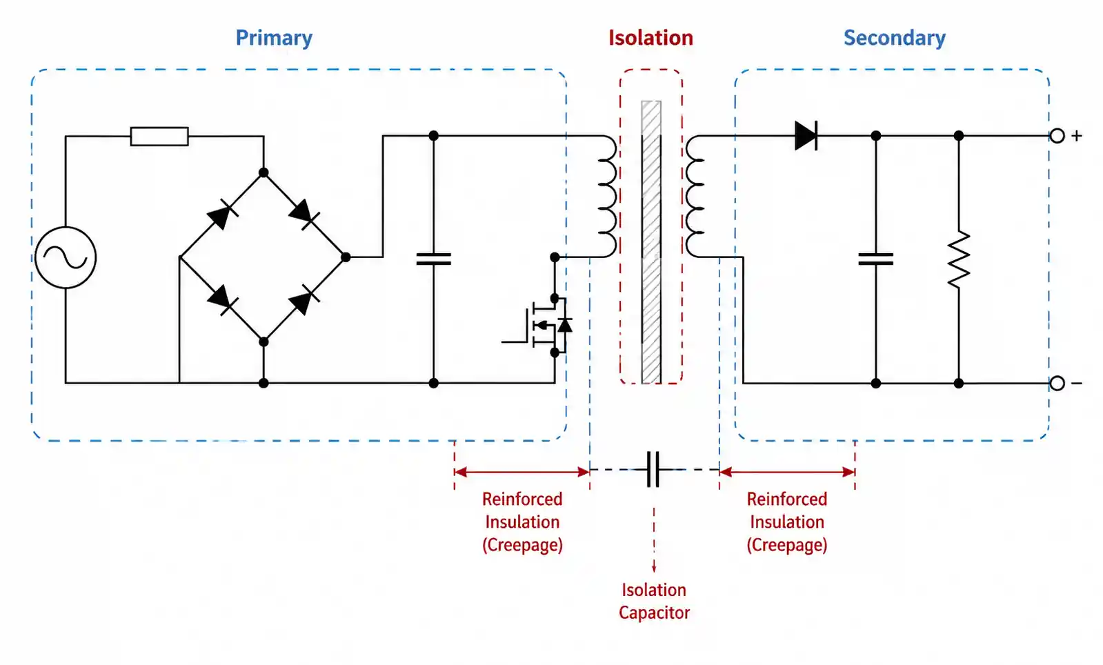
What is the difference between Class I and Class II adapters?
Class I adapters use protective earth (three-prong plug) as the primary safety mechanism against insulation failure. Class II adapters use reinforced or double insulation (two-prong plug) without requiring protective earth connection. Class II designs dominate portable consumer electronics due to universal outlet compatibility and reduced cable cost. Industrial equipment often specifies Class I for enhanced protection and better EMI grounding.
8. Conclusion and Recommended Next Steps
Picking an AC adapter is always a balancing act—voltage, current, size, certifications, and cost all fight for attention. But the real trick is to prioritize based on your actual application, not some generic checklist.
For consumer gear headed to global markets, focus on universal input and DOE Level VI / EU CoC to keep SKUs lean. Industrial designs? Put extended temperature, solid EMI, and field‑proven reliability ahead of saving a few cents. Medical systems need early supplier engagement—isolation, leakage, and documentation are non‑negotiable.Before you commit, grab samples and test them hard: temperature extremes, line droop, load transients. And make sure your certification labs are happy.
Need a hand? Hit up your distributor's FAE or the adapter maker's online tools—they've got selection guides that actually save time.