


BT134 vs BT136: Technical Comparison Guide for Triac Selection
When designing AC switching circuits for consumer electronics, industrial controls, or lighting applications, selecting the right triac is critical for ensuring reliable performance and longevity. The BT134 and BT136 are two widely used triacs from the same product family, but their different current ratings and thermal characteristics make them suited for distinctly different applications. This guide provides a detailed technical comparison to help you make the right choice for your design.
Table of Contents
- Introduction: Why This Comparison Matters
- Key Differences at a Glance
- Parameter-by-Parameter Comparison
- Application Scenario Analysis
- Cost, Availability, and Lead Time Comparison
- When to Use Which Option
- FAQ
- Conclusion
1. Introduction: Why This Comparison Matters
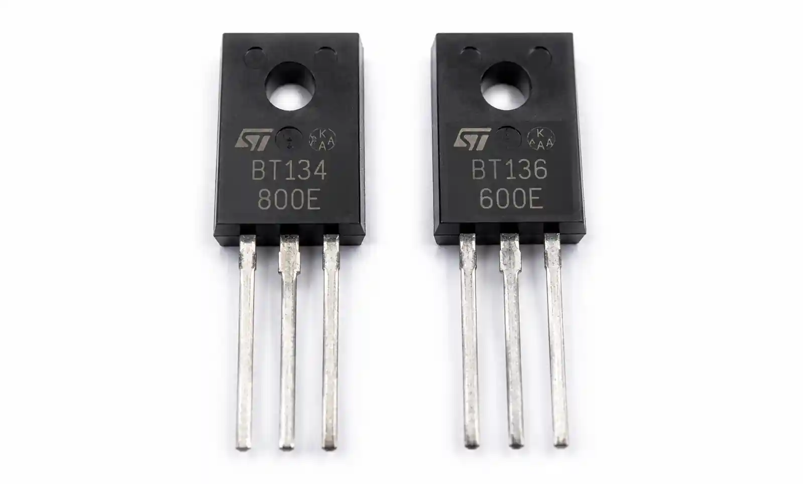
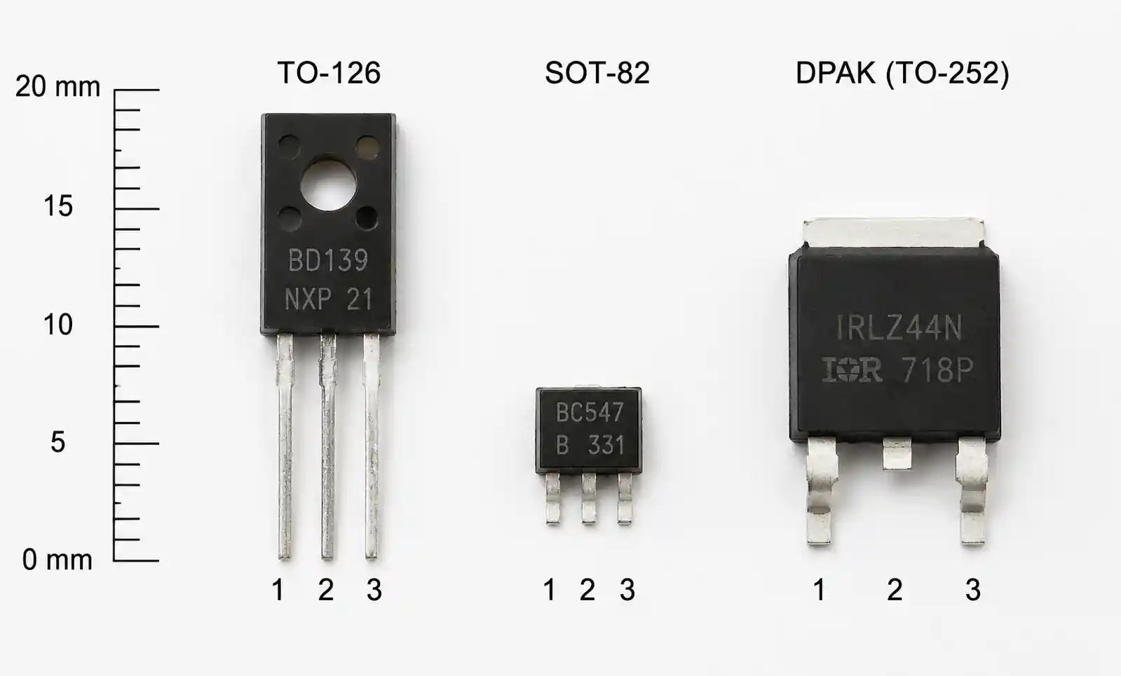
The BT134 and BT136 are both sensitive gate triacs manufactured by multiple vendors including STMicroelectronics, NXP, and others. While they share similar package options (TO-126, SOT-82) and gate sensitivity characteristics, the primary distinction lies in their on-state current ratings: 4A RMS for the BT134 versus 4A RMS for the BT136 (with different peak current capabilities). This seemingly small difference has significant implications for thermal management, PCB layout, heatsinking requirements, and overall system reliability.
Many engineers assume these parts are interchangeable for loads under 4A, but this overlooks critical factors such as surge current handling, dI/dt ratings, and thermal resistance differences that affect real-world performance. Selecting the wrong triac can lead to premature failure, especially in applications with inductive loads or high inrush currents.
This comparison addresses common selection challenges including how to evaluate thermal derating curves, when oversizing makes sense for reliability margins, and how package options affect power dissipation. Whether you're designing a motor speed controller, a lamp dimmer, or a heater control circuit, understanding these differences will help you optimize for performance, cost, and long-term reliability.
2. Key Differences at a Glance
The following table summarizes the critical specifications that differentiate the BT134 and BT136. These parameters directly impact component selection for different power levels and thermal environments.
| Parameter | BT134 | BT136 | Selection Impact |
|---|---|---|---|
| IT(RMS) - On-state current | 4A | 4A | Similar continuous ratings but differ in thermal performance |
| ITSM - Peak surge current (50Hz) | 30A | 25A | BT134 better for high inrush loads |
| VDM - Repetitive peak off-state voltage | 500/600/800V | 500/600/800V | Voltage grades match for both devices |
| IGT - Gate trigger current (Q1) | 5mA max | 5mA max | Same gate sensitivity |
| PG(AV) - Average gate power | 0.2W | 0.2W | Identical gate drive requirements |
| Tj(max) - Maximum junction temp | 125°C | 125°C | Same temperature rating |
| Rth(j-a) - Thermal resistance (TO-126) | 60°C/W | 50°C/W | BT136 has better thermal dissipation |
| Package options | TO-126, SOT-82 | TO-126, SOT-82, DPAK | BT136 offers more package flexibility |
The most significant practical difference is thermal resistance: the BT136's lower Rth(j-a) of 50°C/W versus the BT134's 60°C/W means the BT136 can dissipate approximately 20% more power in free air without a heatsink. This advantage becomes critical in space-constrained designs where external heatsinking is not feasible.
Another key distinction is surge current capability. The BT134's 30A ITSM rating versus the BT136's 25A provides better margin for applications with capacitive or inductive loads that generate high inrush currents during switching. This 20% difference in surge handling can prevent nuisance failures in motor control or transformer-coupled applications.
3. Parameter-by-Parameter Comparison
3.1 On-State Current and Thermal Performance
Both triacs are rated for 4A RMS on-state current, but the critical factor is how this translates to power dissipation and junction temperature rise. The on-state voltage drop (VTM) for both devices is typically 1.3V at 4A (Tj = 25°C), which translates to approximately 5.2W of power dissipation at full load.
Using the thermal resistance values, we can calculate junction temperature rise in free air at full load:
BT134: ΔTj = 5.2W × 60°C/W = 312°C rise (exceeds maximum rating)
BT136: ΔTj = 5.2W × 50°C/W = 260°C rise (still exceeds maximum rating)
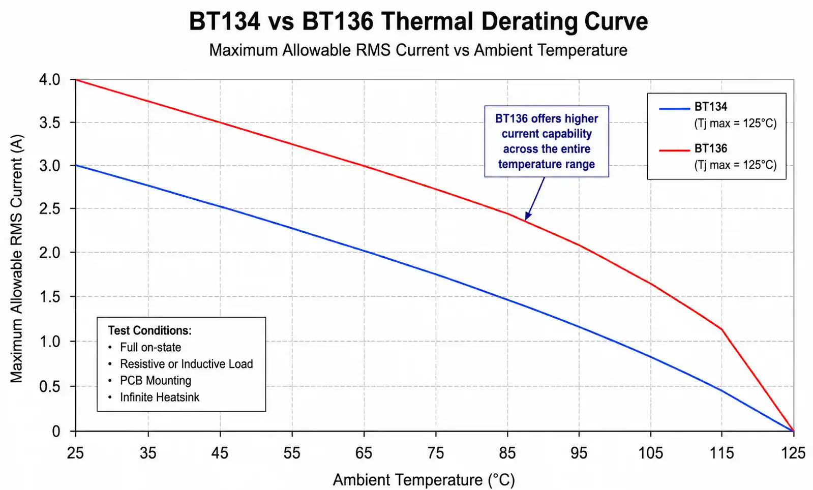
These calculations demonstrate that neither triac can operate at full 4A RMS continuously without heatsinking. However, the BT136's superior thermal resistance provides approximately 17% better thermal performance, which translates to either higher allowable current or reduced heatsink requirements.
In practice, for continuous operation at 4A RMS with a 40°C ambient temperature and 125°C maximum junction temperature, you need to maintain:
BT134: Rth(j-a) ≤ (125°C - 40°C) / 5.2W = 16.3°C/W (requires heatsink with Rth ≈ 17°C/W or better)
BT136: Same calculation yields identical heatsink requirement, but provides better margin
3.2 Gate Trigger Characteristics
Both devices share identical gate trigger specifications, which simplifies driver circuit design when migrating between parts. The maximum gate trigger current (IGT) is 5mA in quadrant I (most sensitive) and 10mA in quadrant III (least sensitive) at 25°C. Gate trigger voltage (VGT) is typically 0.8V with a 2.5V maximum.
For reliable triggering across temperature and device variations, design your gate drive circuit to provide at least 1.5× the maximum IGT, which means 7.5mA minimum for Q1 triggering. A common approach uses a 470Ω resistor from a 5V microcontroller GPIO through an optocoupler, delivering approximately 8-10mA gate current with sufficient margin.
One often-overlooked parameter is gate power dissipation. Both triacs specify 0.2W average gate power, which limits pulse repetition rates in burst-fire control applications. For a 10mA gate current with 2V gate forward drop, each trigger pulse dissipates 20mW. At 120Hz operation (typical for zero-crossing control), this represents minimal gate power (2.4mW average), but phase-control dimmers operating at higher pulse rates need careful gate power budgeting.
3.3 dV/dt and dI/dt Ratings
Both the BT134 and BT136 specify a minimum dV/dt rating of 10V/μs (commutating dV/dt), which represents the maximum rate of voltage rise the device can withstand without false triggering. This specification is particularly important in inductive load switching where back-EMF transients can cause unwanted turn-on.
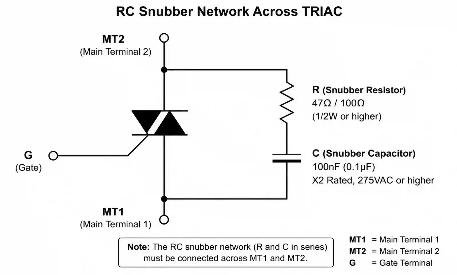
For improved dV/dt immunity in noisy environments, a snubber network (typically 47Ω + 100nF for 120VAC, 100Ω + 100nF for 240VAC) should be placed across the triac terminals. The snubber not only improves dV/dt performance but also reduces EMI and extends triac lifetime by limiting voltage stress.
The critical rate of rise of on-state current (dI/dt) is specified at 10A/μs for both devices. This parameter determines how quickly the triac can transition from blocking to full conduction. Insufficient dI/dt capability causes localized heating near the gate region before the entire silicon area conducts, potentially leading to device failure. Inductive loads naturally limit dI/dt, but resistive and capacitive loads require attention to this specification.
3.4 Voltage Ratings and Breakdown Characteristics
Both triacs are available in 500V, 600V, and 800V repetitive peak off-state voltage (VDRM) grades. For North American 120VAC applications (170V peak), the 500V grade provides a 2.9× derating factor. For European 230VAC applications (325V peak), the 600V grade offers a 1.85× factor, while the 800V grade provides 2.46× margin.
Industry best practice recommends a minimum 2× voltage derating for consumer equipment and 2.5× for industrial applications to account for line transients and switching spikes. In practice, the 600V grade is most commonly stocked by distributors for universal input (85-265VAC) designs, offering good margin without the cost premium of the 800V grade.
The holding current (IH) for both devices is specified at 5-50mA depending on temperature and quadrant. This represents the minimum current required to maintain conduction after gate trigger. In very light load applications or with high-frequency PWM control, ensure load current exceeds the maximum IH specification to prevent drop-out and unstable operation.
4. Application Scenario Analysis
4.1 Residential Lighting Control and Dimmers
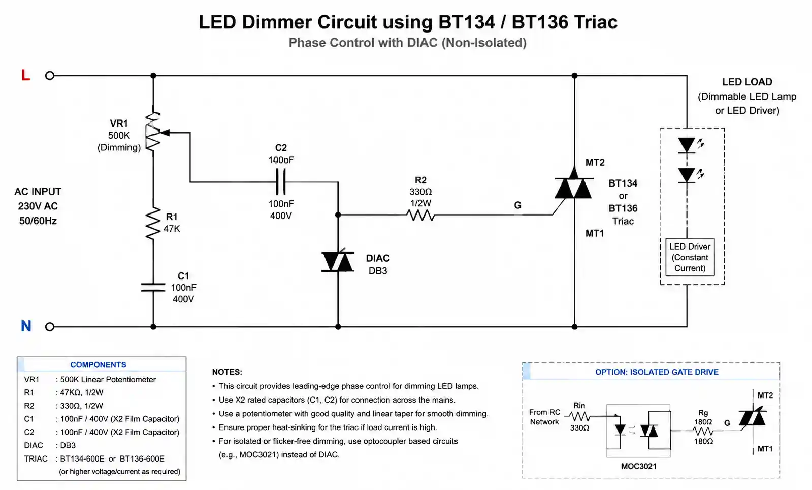
For LED dimmer applications controlling up to 300W loads on 120VAC circuits (approximately 2.5A RMS), both the BT134 and BT136 are technically suitable. However, the BT136 offers advantages in compact enclosures where heat dissipation is limited. The lower thermal resistance allows for higher power density or cooler operation, which extends MTBF in enclosed wall-box installations.
Key design consideration: LED drivers present capacitive loads with high inrush currents. The BT134's superior surge current rating (30A vs 25A) provides better margin against inrush failures, making it the preferred choice despite the BT136's thermal advantage. For 230VAC European applications with similar power levels, current draw is halved, making either device suitable with the BT136 offering better thermal performance.
4.2 Motor Speed Control and Universal Motor Drives
Small universal motors in power tools, vacuum cleaners, and kitchen appliances typically draw 2-8A depending on power level and supply voltage. For sub-4A applications, both triacs are candidates, but the inductive nature of motor loads and high starting currents favor the BT134's higher surge rating.
Motor control circuits benefit from the BT134's ITSM specification when dealing with locked-rotor or stall conditions. A 1/4HP universal motor can draw 6-8× nominal current during starting, which translates to brief surge currents in the 15-25A range. The BT134's 30A surge capability provides adequate margin, while the BT136's 25A rating is marginal for robust design.
For variable-speed control using phase-angle modulation, both devices require attention to dI/dt limiting through appropriate gate drive design. The commutating dV/dt generated by collapsing motor fields during turn-off requires RC snubbers (typically 100Ω + 100nF) to prevent false triggering and extend triac life.
4.3 Heater and Resistive Load Control
Electric heaters represent purely resistive loads, which are the most straightforward application for triacs but also generate the highest steady-state power dissipation due to continuous conduction. For a 1000W heater on 230VAC (4.35A RMS), both triacs operate near their thermal limits and require heatsinking for reliable operation.
In zero-crossing switched applications (burst-fire control) commonly used for temperature control, the average power dissipation is reduced proportionally to duty cycle. At 50% duty cycle, a 4A load dissipates an average of 2.6W in the triac, which is manageable with modest heatsinking (Rth ≈ 30°C/W) for both devices.
The BT136's thermal advantage becomes significant in high-density multi-channel control boards where multiple triacs are mounted in proximity. The lower thermal resistance allows tighter channel spacing or higher load currents without thermal coupling issues between adjacent channels.
4.4 Transformer Primary Switching
Switching transformer primaries presents unique challenges due to high inrush current from core magnetization and the inductive nature of the load. Small transformers (50-200VA) for control applications typically draw 0.5-2A steady-state but can generate 10-20A inrush pulses lasting several milliseconds.
The BT134's higher ITSM rating makes it the default choice for transformer control applications. When combined with proper snubbing to handle the inductive kick during turn-off, the BT134 provides robust performance. For low-frequency switching (line frequency or below), both devices operate well within their thermal capabilities.
Critical design note: always verify that the transformer's inrush duration and magnitude fall within the triac's ITSM specification at the actual switching frequency. Refer to the manufacturer's surge current derating curve for pulse durations exceeding one half-cycle.
5. Cost, Availability, and Lead Time Comparison
| Supply Chain Factor | BT134 | BT136 | Notes |
|---|---|---|---|
| Typical unit price (1K qty) | $0.15-0.25 | $0.18-0.28 | Prices vary by voltage grade and package |
| Global distributor stock | High | Very High | BT136 more widely stocked |
| Alternative sources | Multiple | Multiple | Both available from ST, NXP, WeEn, Littelfuse |
| Lead time (standard) | 8-12 weeks | 8-12 weeks | Factory lead times similar |
| Lead time (distributor stock) | Immediate | Immediate | Both commonly stocked |
| Minimum order quantity (MOQ) | 2,500-5,000 | 2,500-5,000 | Standard for direct factory orders |
| Package availability | TO-126, SOT-82 | TO-126, SOT-82, DPAK | BT136 offers more options |
| End-of-life risk | Low | Low | Mature products with stable demand |
From a procurement perspective, the BT136 enjoys slightly better availability across major distributors (Digi-Key, Mouser, Arrow, Avnet), likely due to its broader application range and multiple package options. The DPAK (TO-252) surface-mount package available for the BT136 but not the BT134 makes it the preferred choice for automated assembly and high-volume production.
Price differences between the two parts are minimal, typically within 10-15% depending on order volume and voltage grade. The 600V grade generally commands a 5-10% premium over the 500V grade, while the 800V grade is 15-20% higher. For cost-sensitive applications, optimizing voltage grade selection based on actual application requirements offers more savings potential than choosing between BT134 and BT136.
Lead times for both components have stabilized following post-pandemic supply chain disruptions, with most distributors maintaining adequate stock levels for immediate shipment of common grades and packages. For high-volume production requiring direct factory orders, plan for 8-12 week lead times and consider dual-sourcing from multiple manufacturers to mitigate supply risk.
6. When to Use Which Option
6.1 Choose BT134 When:
High surge current applications: If your load generates inrush currents exceeding 20A or you need maximum surge margin, the BT134's 30A ITSM rating provides 20% better protection than the BT136. This includes motor starting, transformer switching, and capacitive load applications.
Cost-optimized designs with adequate thermal management: When heatsinking is already required and thermal resistance differences are not the limiting factor, the BT134's typically 10-15% lower cost makes it the economical choice for high-volume production.
Through-hole assembly preference: For prototype builds, repair applications, or low-volume production where through-hole assembly is preferred, both TO-126 and SOT-82 packages are readily available for the BT134.
Existing designs and drop-in replacement: If your existing design uses the BT134 and operates reliably, there's no compelling reason to change unless you're addressing thermal limitations or increasing load current.
6.2 Choose BT136 When:
Thermal performance is critical: In space-constrained enclosures, high ambient temperature environments (>40°C), or designs targeting operation without heatsinks, the BT136's 50°C/W thermal resistance provides approximately 17% better heat dissipation than the BT134's 60°C/W.
Surface-mount assembly required: The BT136's availability in DPAK (TO-252) package enables automated pick-and-place assembly and improved thermal coupling to the PCB ground plane through the mounting tab, making it the only choice for SMT production.
Multi-channel high-density layouts: When designing control boards with multiple triacs in close proximity, the BT136's better thermal characteristics reduce thermal coupling between channels and allow tighter component spacing.
Future load growth or universal designs: If there's potential for load current increases in future product variants or you're designing a universal control platform for multiple power levels, the BT136's thermal headroom provides better scalability.
Maximum availability and sourcing flexibility: The BT136's broader distribution and multiple package options provide better supply chain resilience and faster time-to-market, particularly important for new designs in development.
7. FAQ
What is the main difference between BT134 and BT136 triacs?
Both are 4A RMS triacs with similar electrical specifications, but the BT136 has better thermal performance (Rth(j-a) = 50°C/W vs 60°C/W) while the BT134 offers higher surge current capability (30A vs 25A ITSM). The BT136 is also available in surface-mount DPAK package, which the BT134 is not.
Can I directly replace a BT134 with a BT136 in my existing design?
Yes, the BT134 and BT136 are pin-compatible and electrically similar enough for direct substitution in most applications. However, verify that your application doesn't rely on the BT134's higher surge current rating. The BT136's improved thermal performance is only beneficial, not detrimental, so thermal considerations won't prevent substitution.
Do these triacs require heatsinks for 4A operation?
Yes, both triacs require heatsinking for continuous 4A RMS operation. At full load, on-state power dissipation is approximately 5.2W, which exceeds the capability of either device in free air. For loads under 2A or duty-cycled operation, heatsinking may not be required depending on ambient temperature and enclosure design.
What snubber values should I use for inductive loads?
For 120VAC applications, a 47Ω resistor in series with a 100nF capacitor (rated for 250VAC or higher) provides adequate snubbing for most inductive loads under 5A. For 230VAC applications, increase the resistor to 100Ω while maintaining the 100nF capacitor. Always use film capacitors (polypropylene or polyester) rated for AC line voltage with appropriate safety certifications.
Are these triacs suitable for LED dimming applications?
Yes, both triacs work in LED dimmer designs, but performance depends heavily on the LED driver topology. Leading-edge (TRIAC-based) dimmers work best with dimmable LED drivers specifically designed for TRIAC compatibility. Holding current requirements (5-50mA) can cause compatibility issues with very low wattage LED loads. Consider a 220kΩ bleed resistor across the triac if dimming instability occurs at low settings.
How do I calculate the required heatsink thermal resistance?
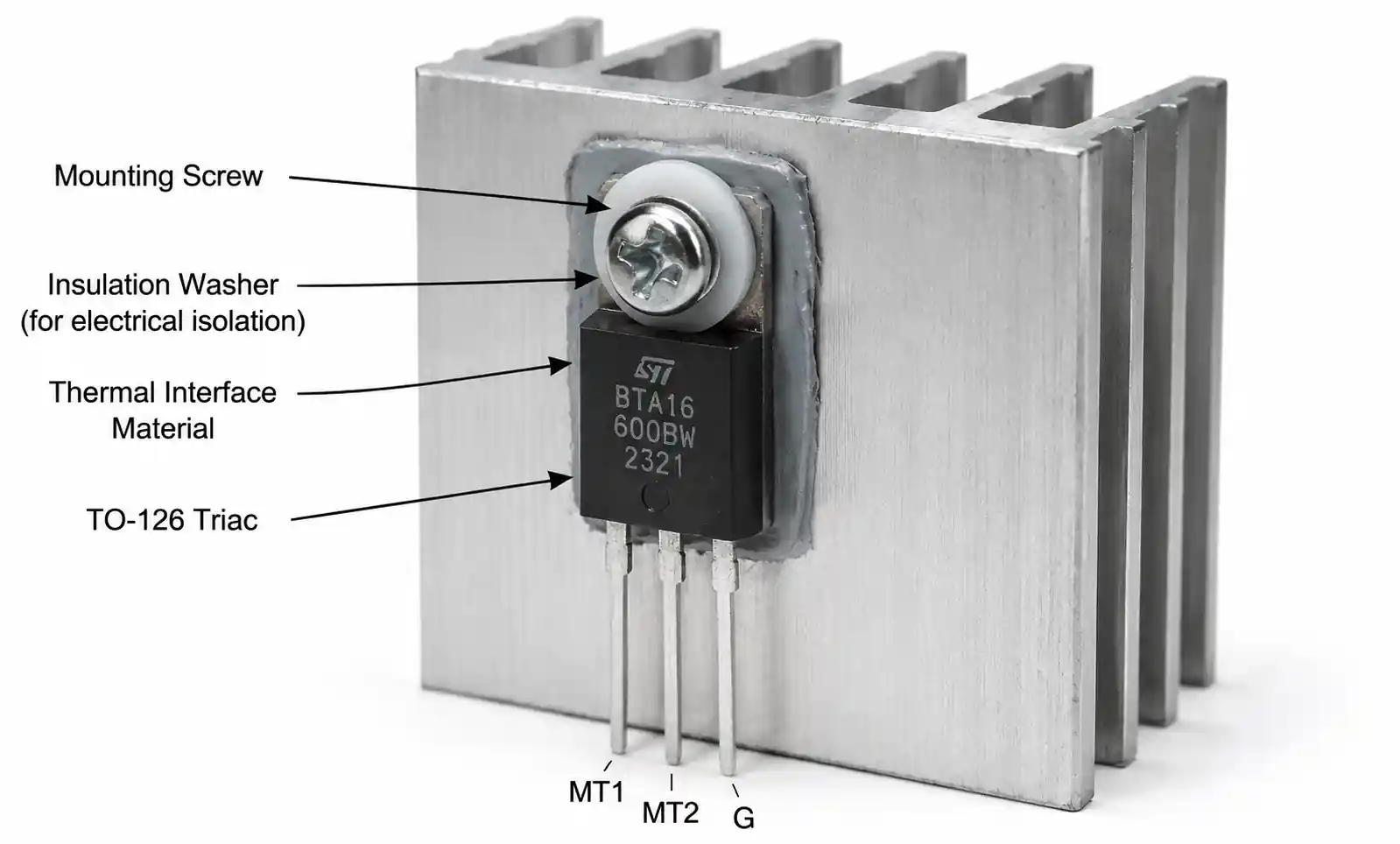
Use the formula: Rth(heatsink) ≤ [(Tj(max) - Ta) / Pd] - Rth(j-c) - Rth(c-s), where Tj(max) is maximum junction temperature (125°C), Ta is ambient temperature, Pd is power dissipation (I × VTM), Rth(j-c) is junction-to-case thermal resistance (typically 2-3°C/W), and Rth(c-s) is thermal interface resistance (0.5-1°C/W with thermal compound). Always include margin for component tolerance and aging.
What are common failure modes for these triacs?
The most common failures are thermal runaway from insufficient heatsinking, gate damage from excessive trigger current or voltage spikes, and junction failure from exceeding surge current ratings during inrush conditions. EMI-induced false triggering can also cause application failures but doesn't typically damage the device. Proper snubbing, gate protection, and thermal management prevent most failure modes.
Which voltage grade should I select for universal input (85-265VAC) applications?
For universal input designs, the 600V grade is the standard choice, providing adequate margin across the full input range. The 800V grade offers additional protection against line transients but at a 15-20% cost premium. The 500V grade is insufficient for 230VAC applications and should only be used for fixed 120VAC installations.
8. Conclusion
Choosing between the BT134 and BT136 comes down to what matters most in your design. The BT134 handles bigger inrush currents (30A vs 25A), so it's better for motor loads, transformers, or anything that kicks hard at startup. The BT136 runs cooler (50°C/W vs 60°C/W) and comes in surface‑mount packages—perfect if you're tight on board space or going with automated assembly.
For most residential or light industrial jobs under 3A, either one works fine with a decent heatsink. Often, the real decision is through‑hole vs SMT, not electrical specs.Before you order, grab the datasheet for your specific voltage and package—pay special attention to derating at your ambient temperature and surge current for your worst‑case startup.
Need help with gate drive, snubbers, or just a sanity check? Talk to your distributor's FAE or check ST/NXP app notes—they have solid reference designs.