ECU Selection Guide: How to Choose the Right Engine Control Unit for Automotive Applications
Table of Contents
- What is an ECU and Why Selection Matters
- Key Technical Parameters Explained
- How to Choose the Right ECU for Your Application
- Performance Comparison: Different ECU Types
- Design Considerations and Common Pitfalls
- Supply Chain and Sourcing Considerations
- FAQ
- Conclusion and Next Steps
1. What is an ECU and Why Selection Matters
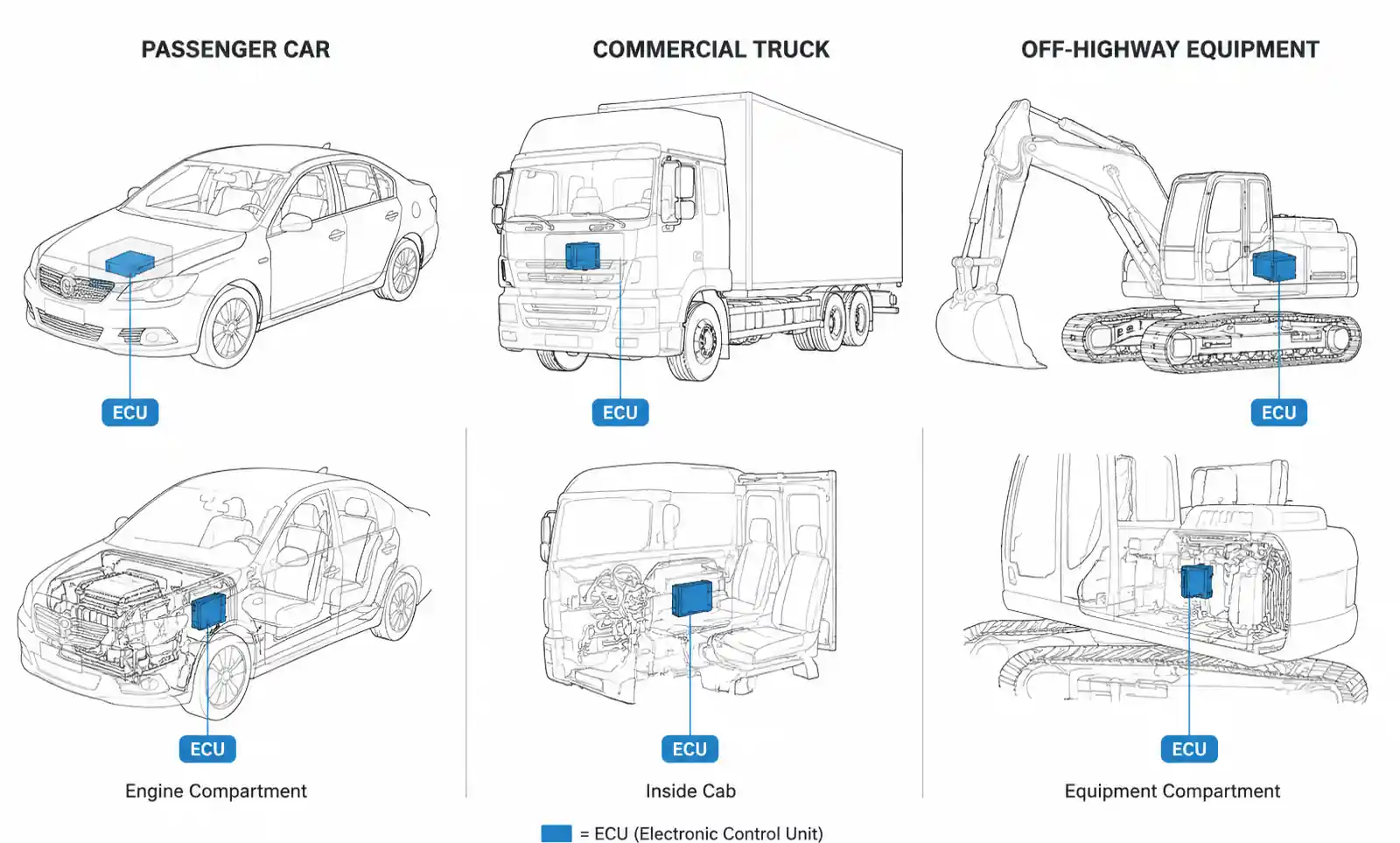
An Engine Control Unit (ECU) is the central electronic control module that manages critical engine functions in modern vehicles. The ECU continuously monitors sensor inputs and adjusts actuator outputs to optimize engine performance, fuel efficiency, emissions control, and reliability. In automotive electronics, ECU selection directly impacts vehicle performance, regulatory compliance, and long-term system reliability.
For automotive engineers and product designers, selecting the right ECU involves balancing processing power, real-time performance, environmental durability, functional safety requirements, and supply chain availability. A poorly specified ECU can lead to delayed time-to-market, compliance failures, or costly redesigns during validation testing.
This guide focuses on the technical parameters and selection methodology that automotive engineers need when evaluating ECUs for passenger vehicles, commercial vehicles, and off-highway equipment. Whether you're designing a new powertrain system or replacing an obsolete ECU in an existing platform, understanding these fundamentals will help you make informed decisions that balance performance, cost, and regulatory requirements.
2. Key Technical Parameters Explained
When evaluating an ECU for automotive applications, several core technical parameters determine system capability and application suitability. Understanding these specifications is essential for proper component selection and system integration.
Processing Power and Architecture
Modern automotive ECUs typically use 32-bit microcontrollers with processing speeds ranging from 80 MHz to 300 MHz. The processor architecture must handle real-time control loops, sensor data acquisition, actuator control, and diagnostic functions simultaneously. For gasoline direct injection systems, processing speeds above 150 MHz are typically required to manage injection timing with microsecond precision. Diesel engine control often demands even higher computational capability due to multiple injection events per combustion cycle.
Memory Configuration
ECUs require both program memory (Flash) and data memory (RAM) with sufficient capacity and access speed. Typical Flash memory ranges from 2 MB to 8 MB for passenger car applications, while RAM requirements range from 256 KB to 1 MB. Systems implementing advanced features like adaptive learning, predictive diagnostics, or over-the-air update capability require higher memory allocation. The memory must also meet automotive temperature specifications and maintain data integrity over the vehicle lifetime.
Input/Output Capability
The number and type of I/O channels determine which sensors and actuators the ECU can interface with. Critical parameters include analog input channels (typically 16-32 channels), digital input channels (8-24 channels), PWM output channels (8-16 channels), and high-side/low-side driver outputs for actuator control. Input voltage ranges must accommodate sensor types including thermistors, pressure sensors, position sensors, and knock sensors. Output current capability varies from 0.5A for low-power solenoids to 5A or higher for high-current actuators.
Communication Protocols
Automotive ECUs must support multiple communication protocols for sensor interfaces, actuator control, and vehicle network integration. CAN (Controller Area Network) is standard, with modern systems supporting CAN FD for higher bandwidth. Additional protocols include LIN for cost-sensitive subsystems, FlexRay for safety-critical applications, and Ethernet for advanced driver assistance systems. The ECU must handle message throughput requirements while maintaining real-time control loop execution.
Environmental and Reliability Specifications
Automotive ECUs operate in harsh environments with extreme temperature variations, vibration, electromagnetic interference, and potential exposure to fluids. Operating temperature range typically spans -40°C to +125°C for the electronics, with higher temperatures at the case depending on mounting location. Vibration resistance must meet automotive standards, typically 10G to 20G depending on mounting location. EMC compliance requires meeting ISO 7637 for electrical transients and CISPR 25 for radiated emissions.
3. How to Choose the Right ECU for Your Application
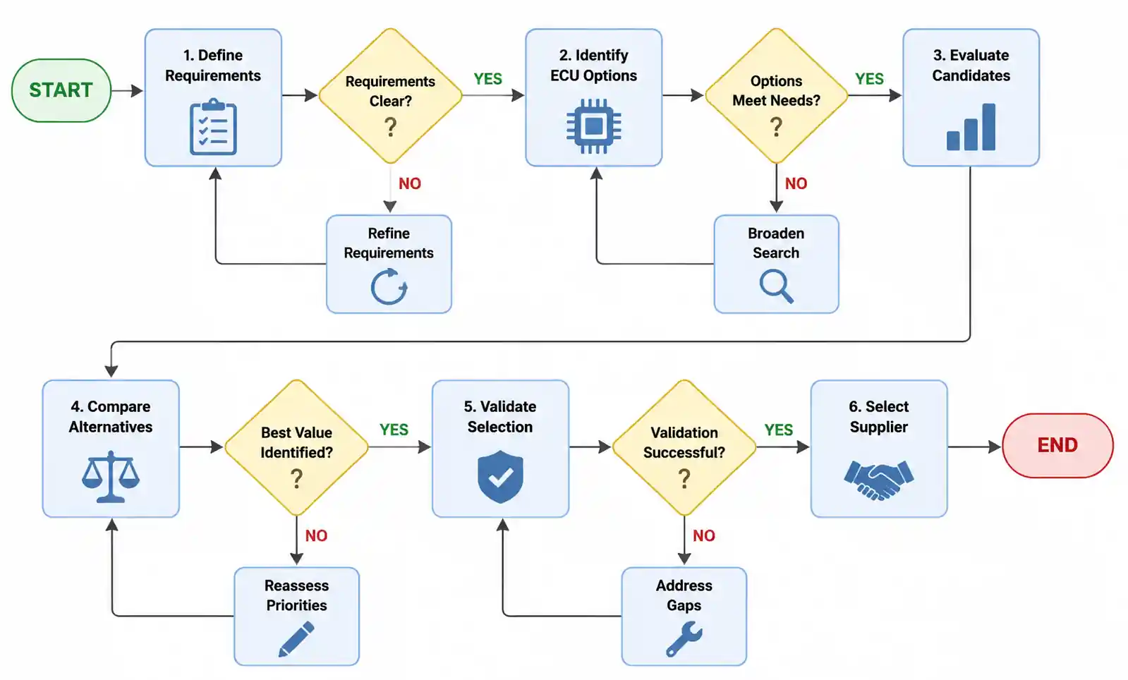
ECU selection requires a systematic approach that matches technical requirements with application constraints. This methodology helps narrow the selection from hundreds of available options to a short list of viable candidates.
Step 1: Define Functional Requirements
Begin by documenting all engine management functions the ECU must perform. This includes fuel injection control, ignition timing, variable valve timing, turbocharger control, exhaust gas recirculation, and emissions after-treatment. For each function, identify the required sensor inputs and actuator outputs with their electrical characteristics. Count the total number of analog inputs, digital inputs, PWM outputs, and high-current driver outputs needed. Add 20-30% margin for future feature additions or design changes discovered during validation.
Step 2: Establish Performance Requirements
Determine the control loop timing requirements based on engine speed and control precision needs. At 6000 RPM, a four-stroke engine completes 50 combustion cycles per second, requiring control loop execution every 20 milliseconds or faster. Injection timing precision requirements typically demand microsecond-level timing accuracy. Map these timing requirements to processor speed and architecture capabilities. Consider whether the application requires single-core or multi-core processing based on functional safety requirements and task partitioning needs.
Step 3: Assess Regulatory and Safety Requirements
Identify applicable safety standards based on vehicle type and market. ISO 26262 defines functional safety requirements for automotive systems, with most engine control functions classified as ASIL-B or ASIL-C. This classification impacts processor selection, software architecture, and diagnostic requirements. Emissions regulations (EPA Tier 3, Euro 6, China 6) mandate specific diagnostic capabilities and on-board monitoring functions. Ensure the ECU hardware supports the required diagnostic protocols including OBD-II or WWH-OBD.
Step 4: Evaluate Environmental Constraints
Consider the ECU mounting location and environmental exposure. Engine-mounted ECUs experience higher temperatures and vibration compared to firewall-mounted units. Underhood temperatures can reach 125°C or higher near exhaust components. Vibration levels vary significantly between passenger cars and commercial vehicles or off-highway equipment. Select ECUs with environmental ratings that exceed your worst-case conditions by at least 10°C and 20% vibration margin.
Step 5: Analyze Supply Chain Factors
Evaluate component availability, lead times, and lifecycle support. Automotive programs typically require 10-15 year component availability. Verify that the ECU supplier commits to long-term supply and provides obsolescence management. Consider regional availability if manufacturing occurs in multiple locations. Evaluate second-source options for critical components to mitigate supply chain risk.
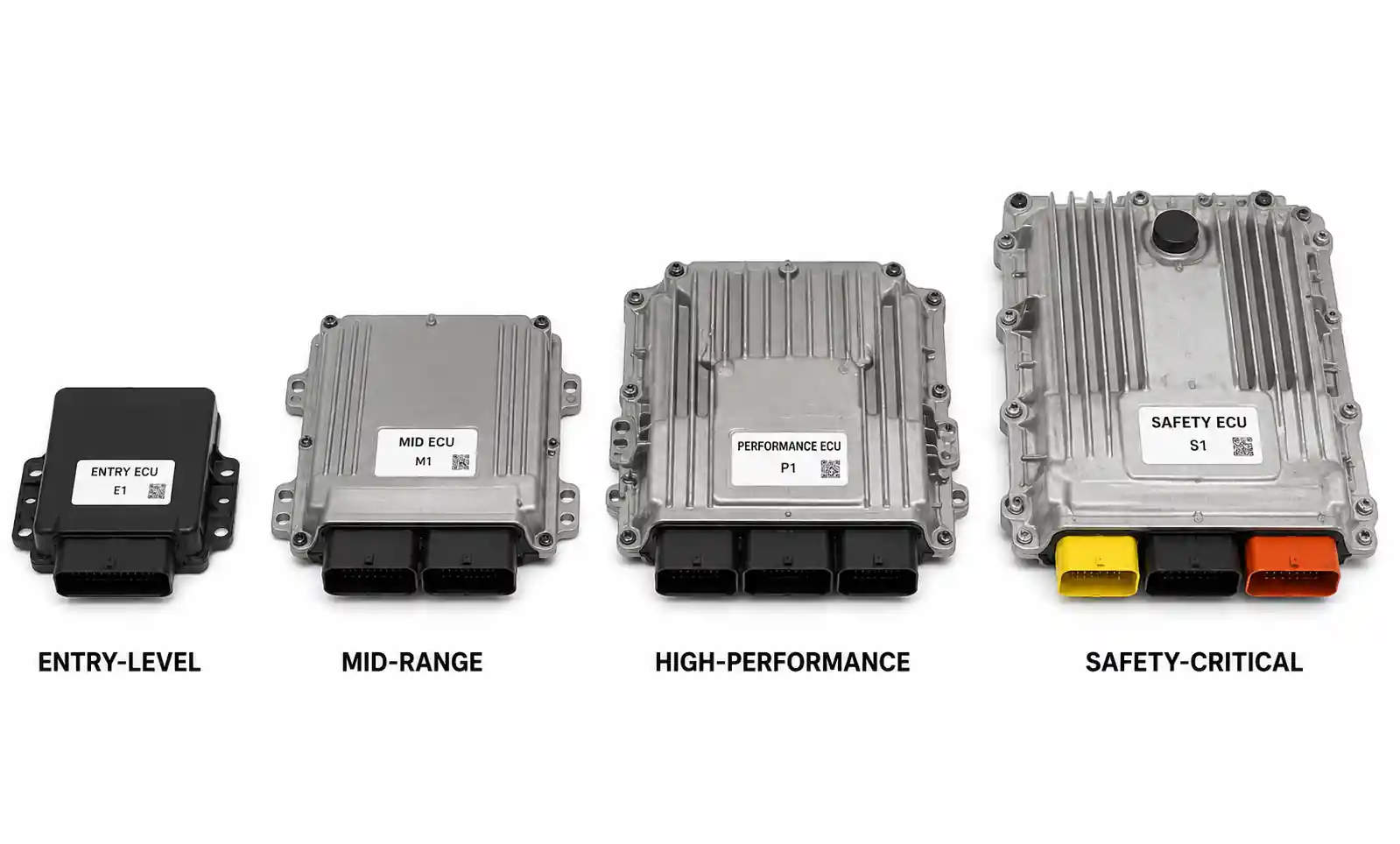
4. Performance Comparison: Different ECU Types
ECUs are available in several configurations optimized for different vehicle types and performance requirements. Understanding these categories helps narrow selection based on application needs.
| ECU Type | Processor Speed | I/O Channels | Target Application | Typical Cost Range | Key Differentiator |
|---|---|---|---|---|---|
| Entry-Level ECU | 80-120 MHz | 20-30 analog, 10-15 digital | Small displacement engines, cost-sensitive markets | $80-$150 | Basic fuel and ignition control |
| Mid-Range ECU | 120-180 MHz | 30-45 analog, 15-25 digital | Mainstream passenger vehicles, light commercial | $150-$300 | Variable valve timing, turbo control |
| High-Performance ECU | 180-300 MHz | 45-60 analog, 25-35 digital | Performance vehicles, heavy-duty diesel | $300-$600 | Advanced control algorithms, multi-core |
| Safety-Critical ECU | 200-300 MHz | 40-55 analog, 20-30 digital | ISO 26262 ASIL-C/D applications | $400-$800 | Redundant processing, lockstep cores |
This comparison table shows the trade-offs between processing capability, I/O flexibility, and cost. Entry-level ECUs suit naturally aspirated gasoline engines in cost-sensitive markets where advanced features are not required. Mid-range ECUs represent the volume segment for modern passenger vehicles with turbocharged engines and emissions controls. High-performance ECUs support demanding applications including gasoline direct injection, diesel common rail systems, and performance-oriented calibrations. Safety-critical ECUs incorporate redundant processing and diagnostic capabilities required for fail-operational systems.
The cost differential between categories reflects not only hardware capability but also software development investment, safety certification costs, and validation requirements. When selecting between categories, consider the total system cost including software development, calibration effort, and validation testing rather than hardware cost alone.
Application-Specific Selection Matrix
| Application Scenario | Recommended ECU Type | Critical Parameters | Typical Lead Time |
|---|---|---|---|
| Naturally aspirated gasoline, <2.0L | Entry-Level | 80+ MHz, 25+ analog inputs | 12-16 weeks |
| Turbocharged gasoline with VVT | Mid-Range | 150+ MHz, 35+ analog inputs, 10+ PWM outputs | 16-20 weeks |
| Diesel with common rail and EGR | High-Performance | 200+ MHz, 40+ analog inputs, CAN FD support | 20-26 weeks |
| Hybrid powertrain integration | Safety-Critical | Dual-core, ISO 26262 ASIL-C certified | 26-32 weeks |
| Heavy-duty commercial vehicle | High-Performance | -40°C to +125°C, 20G vibration rated | 20-26 weeks |
This matrix provides practical guidance for matching ECU categories to common application scenarios. The lead time estimates include component procurement and initial validation testing but do not include full calibration and certification, which adds 6-12 months to total program timing.
5. Design Considerations and Common Pitfalls
Proper ECU integration requires attention to several critical design aspects that significantly impact system reliability and performance. Many issues discovered during validation testing trace back to fundamental design decisions made during ECU selection and system architecture.
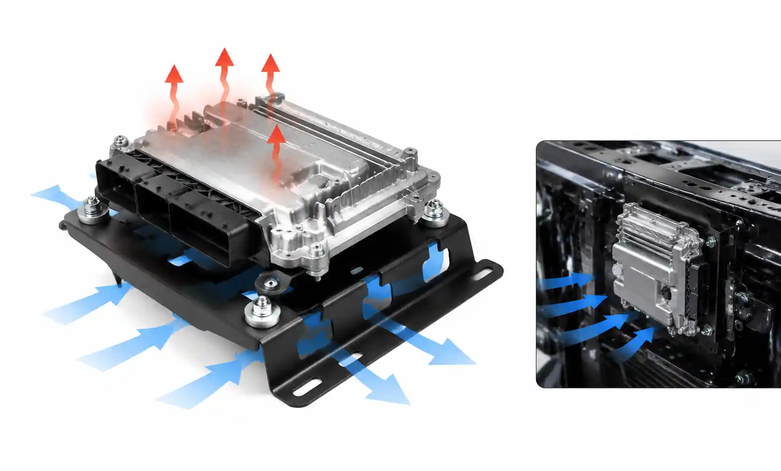
Thermal Management
ECU thermal design is often underestimated during initial selection. Power dissipation in modern ECUs ranges from 15W to 50W depending on I/O configuration and processing load. When mounted in high-temperature locations near the engine, inadequate thermal design leads to junction temperatures exceeding specifications, causing intermittent failures or reduced lifespan. Calculate total power dissipation including all active drivers and processing load, then verify that the thermal path from semiconductor junctions to ambient provides adequate cooling margin. A common mistake is testing only at room temperature during validation without simulating worst-case underhood temperatures combined with high electrical loads.
Grounding and Shielding
Poor grounding design causes the majority of EMC-related failures in automotive ECU applications. The ECU requires separate power and signal grounds with low-impedance return paths to the battery negative terminal. Signal grounds should connect to power ground only at a single point to prevent ground loops. Sensor signal wiring requires twisted-pair or shielded cables with proper shield grounding at the ECU end only. A common pitfall is using chassis ground points far from the ECU, which introduces voltage drops and noise pickup in the ground reference. This becomes particularly problematic for analog sensors where millivolt-level signals require clean ground references.
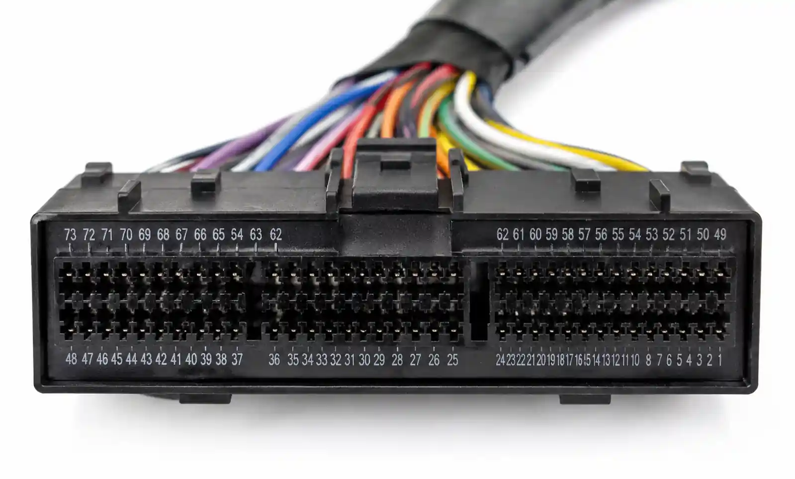
Connector Selection and Pinout Strategy
Automotive connectors must withstand vibration, temperature cycling, and potential fluid exposure while maintaining reliable electrical contact over the vehicle lifetime. Select connectors rated for automotive applications with sealed designs meeting IP67 or higher. Organize the pinout to separate high-current drivers from sensitive analog inputs to minimize crosstalk. Reserve pins adjacent to analog inputs for ground shields rather than switching signals. A frequently overlooked consideration is connector availability during prototyping and production, as automotive-grade connectors often have long lead times and minimum order quantities that impact program timing.
Software Architecture Limitations
ECU hardware capabilities must align with software architecture requirements. Real-time operating systems require specific processor features including memory protection units and hardware timers. Safety-critical applications following ISO 26262 may mandate specific microcontroller features for error detection and handling. Verify that the selected ECU supports your software toolchain and that sufficient program memory remains after accounting for diagnostic routines, calibration data, and software updates. A common mistake is underestimating code size growth during development, leaving insufficient margin for bug fixes and feature additions discovered during validation.
Diagnostic and Service Requirements
Modern vehicles require extensive diagnostic capabilities for production testing, warranty service, and emissions compliance. The ECU must support diagnostic communication protocols including UDS (Unified Diagnostic Services) and provide sufficient memory for diagnostic trouble code storage and freeze frame data. Plan for remote programming capability if your product roadmap includes over-the-air updates. Inadequate diagnostic capability discovered late in development requires expensive hardware changes or limits service capabilities in the field.
6. Supply Chain and Sourcing Considerations
ECU procurement requires attention to several supply chain factors beyond technical specifications and price. Automotive production schedules are unforgiving, and component shortages directly impact vehicle manufacturing.
Lead Time Management
Standard ECU lead times range from 12 to 32 weeks depending on complexity and customization requirements. High-volume automotive suppliers typically require 16-20 weeks for production ECUs after design freeze. This timeline includes component procurement, PCB assembly, software programming, and functional testing. Custom ECUs with specific connector configurations or modified I/O layouts add 4-8 weeks for tooling and first article inspection. During industry-wide semiconductor shortages, lead times can extend to 40+ weeks. Successful programs maintain 8-12 weeks of ECU inventory as buffer stock and establish long-term supply agreements with volume commitments.
Lifecycle and Obsolescence
Automotive programs require component availability for 10-15 years to support production and service requirements. When selecting an ECU, verify that the supplier commits to long-term supply with formal obsolescence notification procedures. Leading suppliers provide 3-5 year advance notice before discontinuing automotive components, allowing time for qualification of replacement parts. Establish a proactive obsolescence monitoring process that tracks not only the ECU but also critical semiconductor components within the ECU. A common mistake is assuming that standard industrial ECUs will remain available for automotive lifecycles without formal supply agreements.
Quality and Certification
Automotive ECUs must meet stringent quality requirements defined by IATF 16949 and customer-specific standards. Verify that your supplier maintains appropriate quality certifications and conducts PPAP (Production Part Approval Process) documentation. Request quality metrics including DPPM (defects per million parts) history and field return rates. For applications requiring functional safety certification, ensure the ECU includes relevant ISO 26262 documentation and safety manual. Quality-related issues discovered after production launch result in expensive recalls and warranty costs that far exceed any initial procurement savings.
Regional Sourcing and Tariffs
For global vehicle programs, consider regional sourcing strategies that minimize logistics costs and tariff exposure. Manufacturing ECUs in the same region as vehicle assembly reduces lead time, freight costs, and potential customs delays. However, regional sourcing must balance cost optimization with supplier capability and quality requirements. Evaluate total landed cost including tariffs, freight, and inventory carrying costs rather than focusing solely on unit price.
7. FAQ
What is the typical lifespan of an automotive ECU?
Automotive ECUs are designed for 15-20 year operational lifespans under normal conditions. However, actual lifespan depends on operating temperature, vibration exposure, and electrical stress. ECUs mounted directly on the engine experience harsher conditions and may require replacement at 10-12 years, while firewall-mounted units in controlled environments often exceed 20 years. Component degradation primarily affects electrolytic capacitors and connector contacts rather than semiconductor devices.
Can I use an industrial-grade ECU for automotive applications?
Industrial ECUs lack critical automotive qualifications and will fail regulatory compliance. Automotive ECUs must meet IATF 16949 quality requirements, ISO 26262 functional safety standards for safety-critical functions, and automotive EMC standards including ISO 7637 and CISPR 25. Additionally, automotive connectors, operating temperature ranges, and vibration resistance differ substantially from industrial specifications. Using non-automotive components creates liability risk and certification delays.
How do I calculate the required processing speed for my application?
Calculate processing requirements by determining the fastest control loop timing needed. For gasoline direct injection at 6000 RPM, injector timing requires updates every 10 milliseconds. Add computational overhead for sensor processing (20%), actuator control (15%), diagnostics (10%), and communication (10%), leaving 45% margin for real-time operating system and application code. For this example, a 120 MHz processor provides adequate capability. Complex algorithms like model-based controls or adaptive learning require 50-100% additional processing margin.
What are the key differences between ECU types for gasoline and diesel engines?
Diesel ECUs require higher processing speeds (200+ MHz versus 120+ MHz for gasoline) due to multiple injection events per combustion cycle. Diesel systems typically need 8-12 injection control outputs versus 4-6 for gasoline. Diesel applications also require higher pressure sensors (2500+ bar common rail versus 200 bar gasoline direct injection) and additional inputs for EGR control and diesel particulate filter monitoring. Both require similar communication protocols and diagnostic capabilities, but diesel emissions compliance demands more extensive on-board monitoring.
How do I handle ECU obsolescence in a long-running vehicle program?
Establish obsolescence monitoring through your ECU supplier's product change notification process. When obsolescence occurs, evaluate whether a form-fit-function replacement exists with minimal re-validation required. If major redesign is necessary, begin qualification 18-24 months before supply discontinuation. Consider lifetime buy strategies only for low-volume programs where inventory carrying costs are justified. For high-volume programs, transition to replacement ECUs and maintain parallel production during validation to avoid line-down risk.
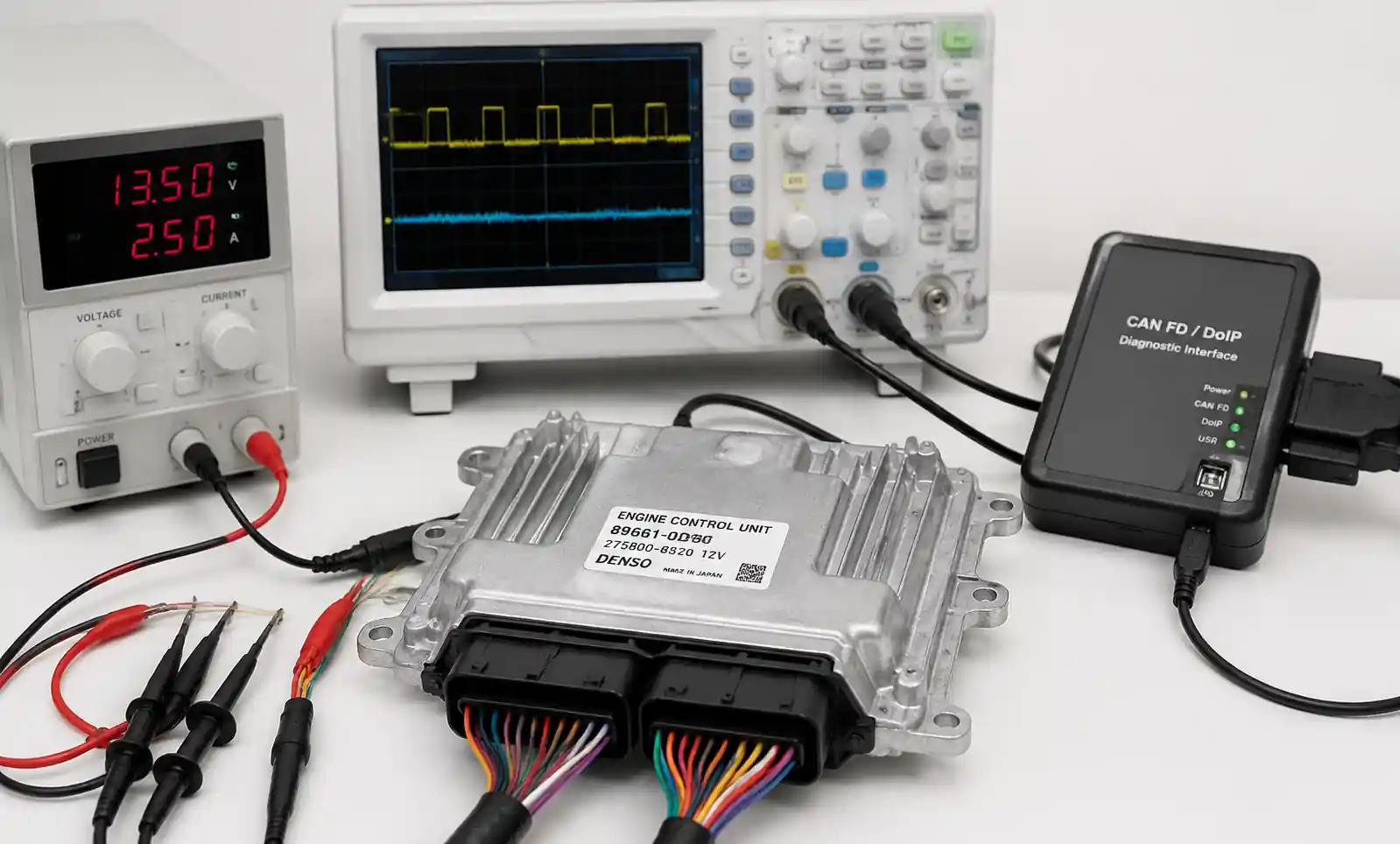
What testing is required to validate ECU selection?
ECU validation includes environmental testing (temperature cycling -40°C to +125°C, vibration per automotive standards, humidity and salt spray), EMC testing (conducted and radiated emissions and immunity), functional testing (all control modes and diagnostic routines), and long-term reliability testing (minimum 2000 hours at elevated temperature). Additionally, vehicle-level validation includes drive cycle testing, emissions certification testing, and safety validation per ISO 26262. Budget 6-12 months for complete validation and certification.
Can I retrofit a newer ECU into an older vehicle platform?
Retrofitting ECUs requires matching electrical interfaces, communication protocols, and software calibration to the existing vehicle architecture. Physical compatibility includes connector pinout, mounting locations, and thermal environment. Functional compatibility requires sensor and actuator electrical specifications to match ECU capabilities. The most significant challenge is software calibration, which requires extensive dynamometer and vehicle testing. Unless the replacement ECU comes with pre-validated calibration for your specific engine, retrofit projects require 3-6 months of calibration development.
What should I look for in ECU datasheets to ensure compatibility?
Critical datasheet parameters include processor speed and architecture, analog input channels with voltage ranges and resolution, digital input specifications including switching thresholds, PWM output channels with frequency and duty cycle ranges, high-side and low-side driver current ratings, communication protocol support (CAN, LIN, etc.), operating temperature range, and environmental ratings for vibration and EMC. Verify that electrical specifications match your sensor output ranges and actuator drive requirements with appropriate safety margins.
8. Conclusion and Next Steps
Picking the right ECU for automotive use is all about trade‑offs: performance, compliance, reliability, and supply. Start by writing down your functional needs and environmental limits, then run through the selection steps and comparison tables in this guide to filter your options.For turbo gas engines with VVT, a mid‑range ECU with 150+ MHz and 35+ analog inputs is usually a pretty good fit. Diesel? You'll want 200+ MHz to handle those complex injection algorithms. If your system is safety‑critical and needs ISO 26262, go for a redundant ECU with certified safety features—costs more but keeps you compliant.
Before you commit, grab detailed datasheets and app notes from suppliers. Check their long‑term supply commitment and quality certs. And budget enough time for environmental, EMC, and functional validation. Bring in their FAE early—they'll catch integration headaches before you spend on tooling.Need more help? Download the full app notes for your engine type or reach out to an FAE for a design review.