


High Rupturing Capacity (HRC) Fuse: Working Principle, Design, and Engineering Applications
High Rupturing Capacity (HRC) fuses are advanced overcurrent protection devices designed to safely interrupt very high fault currents in electrical systems. Unlike standard fuses, HRC fuses incorporate engineered arc-quenching mechanisms, allowing them to operate reliably under extreme fault conditions. This article provides an in-depth engineering analysis of HRC fuse construction, operating principles, performance characteristics, types, ratings, and real-world applications, helping engineers design safer and more robust protection systems.
Table of Contents
- 1. What Is an HRC Fuse?
- 2. Key Performance Characteristics
- 3. Internal Construction and Materials
- 4. Working Principle and Arc Interruption Process
- 5. Types of HRC Fuses
- 6. Advantages and Limitations
- 7. Engineering Applications
- 8. Ratings and Technical Specifications
- 9. Comparison with Other Protection Devices
- 10. Maintenance and Troubleshooting
- 11. Future Trends
- 12. FAQ
- 13. Conclusion
1. What Is an HRC Fuse?
An HRC (High Rupturing Capacity) fuse is a current-limiting, high-breaking-capacity fuse designed to interrupt fault currents that can reach tens or even hundreds of kiloamperes.
Engineering Definition
An HRC fuse is a sealed cartridge fuse capable of safely interrupting high prospective short-circuit currents without explosion or arc escape.
Key Function
- Protect cables, transformers, and switchgear
- Limit fault current magnitude
- Prevent thermal and mechanical damage
2. Key Performance Characteristics
2.1 High Breaking Capacity
- Typically ≥ 80 kA, up to 120 kA or more
- Suitable for industrial fault levels
2.2 Current-Limiting Behavior
- Interrupts fault before peak current is reached
- Reduces electrodynamic stress on equipment
2.3 Inverse Time Characteristic
- Small overload → delayed operation
- Large fault → instantaneous operation
2.4 Thermal Stability
- Designed to withstand high temperatures and pressure during fault interruption
3. Internal Construction and Materials
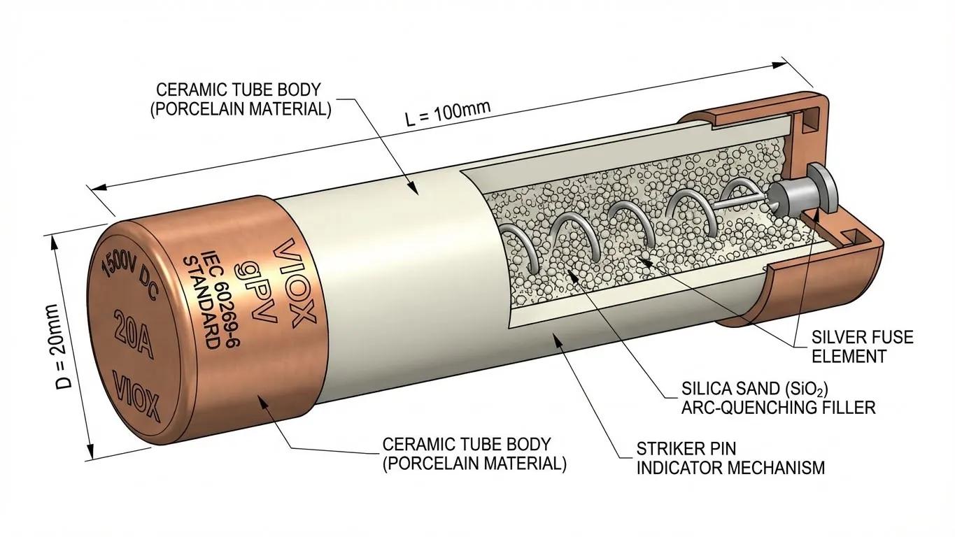
3.1 Core Components
- Ceramic body → high thermal and mechanical strength
- End caps → copper or brass terminals
- Fuse element → silver or copper strip
- Tin joints → controlled weak points
- Filling material → silica (quartz) sand
3.2 Design Purpose
Each component contributes to:
- Controlled melting
- Efficient arc quenching
- Containment of high-pressure gases
4. Working Principle and Arc Interruption Process
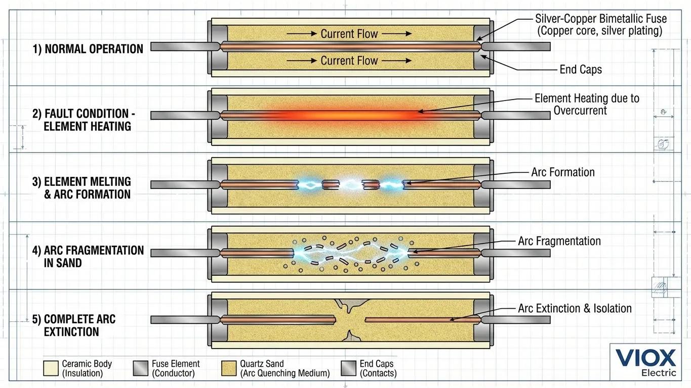
4.1 Normal Operation
- Current flows through the fuse element
- Temperature remains below melting point
4.2 Overload Condition
- Gradual heating occurs
- Tin joints melt first to provide delayed response
4.3 Short Circuit Condition
- Rapid temperature rise
- Fuse element melts and vaporizes
4.4 Arc Formation and Suppression
- Arc forms between separated ends
- Silica sand reacts with metal vapor
- Forms a high-resistance medium
- Arc is extinguished quickly
Engineering Insight
HRC fuses combine thermal, chemical, and mechanical processes to achieve fast and reliable interruption.
5. Types of HRC Fuses
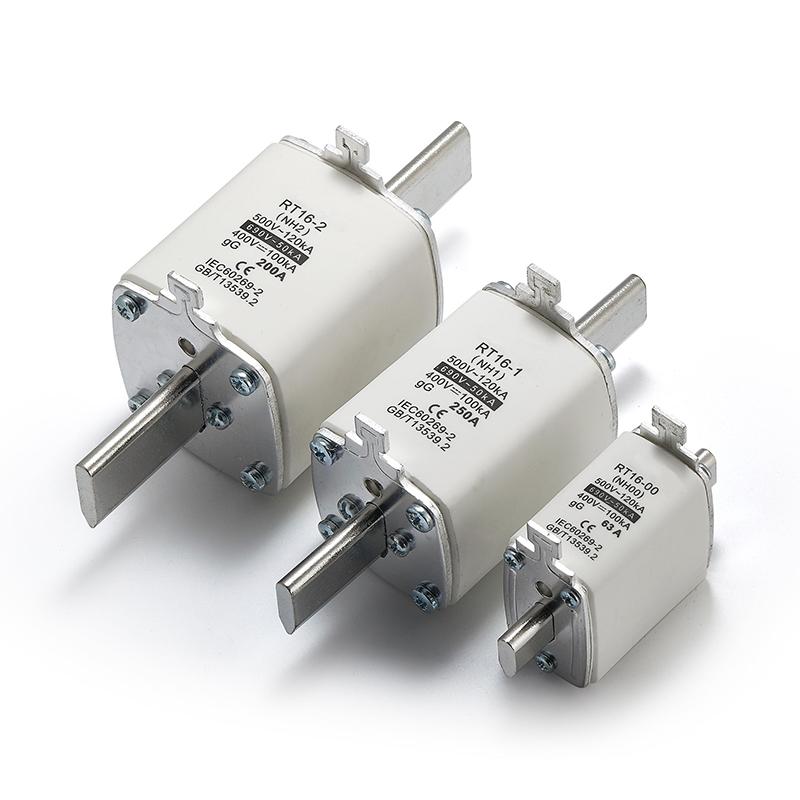
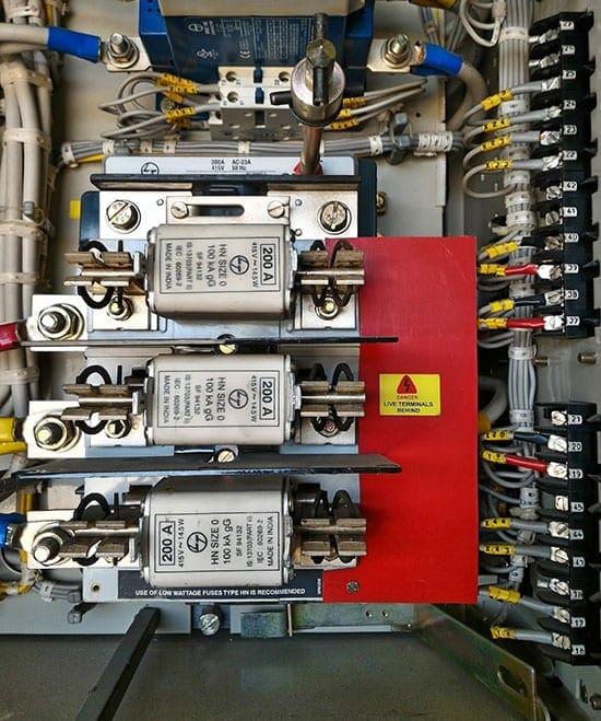
5.1 NH Type
- High current capacity
- Used in industrial distribution systems
5.2 DIN Type
- Standardized dimensions
- Suitable for modular installations
5.3 Blade Type
- Plug-in structure
- Easy installation and replacement
5.4 Cylindrical (Cartridge) Type
- Compact sealed design
- Common in control panels
6. Advantages and Limitations
Advantages
- Very high fault interruption capability
- Fast response time
- Current limiting protection
- High reliability with no moving parts
- Minimal maintenance required
Limitations
- Single-use device
- Requires replacement after operation
- No adjustable settings
- Cannot function as a switch
7. Engineering Applications
7.1 Industrial Systems
- Power distribution networks
- Motor protection circuits
- Transformer protection
7.2 Commercial Systems
- Switchgear panels
- Feeder protection
7.3 Renewable Energy Systems
- Solar photovoltaic systems
- Battery energy storage systems
Engineering Note
HRC fuses are often used as backup protection for circuit breakers in high fault-level systems.
8. Ratings and Technical Specifications
| Parameter | Typical Range |
|---|---|
| Current Rating | 2A – 1250A |
| Voltage Rating | Up to 1000V (low voltage), higher for high-voltage designs |
| Breaking Capacity | Up to 100kA or more |
| Fuse Class | gG (general purpose), aM (motor protection) |
9. Comparison with Other Protection Devices
| Feature | HRC Fuse | LBC Fuse | Circuit Breaker |
|---|---|---|---|
| Breaking Capacity | Very High | Low | Medium to High |
| Response Speed | Very Fast | Moderate | Fast |
| Reusability | No | No | Yes |
| Maintenance | Low | Low | Moderate |
| Best Application | Industrial protection | Low-power circuits | General systems |
10. Maintenance and Troubleshooting
10.1 Inspection Checklist
- Discoloration indicates overheating
- Cracks indicate mechanical failure
- Corrosion affects conductivity
- Loose connections cause heat buildup
10.2 Testing Method
- Isolate the circuit
- Remove the fuse
- Test continuity using a multimeter
- Near 0 Ω → fuse is good
- Infinite → fuse is blown
Safety Rules
- Never test a live fuse
- Never bypass protection
- Always identify the root cause before replacement
11. Future Trends
- Smart fuses with monitoring capability
- Improved ceramic materials for durability
- Compact high-performance designs
- Increasing use in EV and renewable systems
12. FAQ
Q1: What makes HRC fuses different from standard fuses?
They can safely interrupt very high fault currents and include arc-quenching materials.
Q2: What is rupturing capacity?
It is the maximum fault current a fuse can interrupt without failure.
Q3: Why is silica sand used in HRC fuses?
It absorbs heat and helps extinguish the arc by forming a high-resistance medium.
Q4: Are HRC fuses reusable?
No, they must be replaced after operation.
Q5: Where are HRC fuses commonly used?
In industrial systems, switchgear, and high-power applications.
13. Conclusion
HRC fuses are essential components in modern electrical protection systems. Their ability to interrupt high fault currents quickly and safely makes them ideal for industrial and high-power applications. Proper selection, installation, and maintenance ensure system safety, reduce equipment damage, and improve long-term reliability.