


IPC Standards: A Practical Guide for Electronics Design and Manufacturing
When you're designing circuit boards or managing electronics manufacturing, you've probably encountered references to IPC standards in specifications, quality agreements, or supplier documentation. These standards define everything from acceptable solder joint appearance to PCB material requirements. But understanding which standards apply to your project and how to implement them correctly can be challenging.
This guide walks through the most commonly used IPC standards in electronics manufacturing, explains what they actually require in practical terms, and helps you determine which specifications matter most for your application.
Table of Contents
- What Are IPC Standards and Why They Matter
- Core IPC Standards Every Engineer Should Know
- IPC Class Levels: Understanding Acceptance Criteria
- How to Select the Right IPC Class for Your Application
- Common Implementation Challenges and Solutions
- Supply Chain Considerations When Specifying IPC Standards
- FAQ
- Conclusion
1. What Are IPC Standards and Why They Matter
IPC standards originated from the Institute for Printed Circuits, now known as IPC (Association Connecting Electronics Industries). These documents establish industry-wide consensus on manufacturing requirements, quality criteria, and test methods for printed circuit boards and electronic assemblies.
The practical value of IPC standards becomes clear when you consider the alternative: without agreed-upon definitions, terms like "acceptable solder joint" or "clean PCB" mean different things to different manufacturers. One contract manufacturer might accept solder joints you'd reject, while another might scrap boards that meet your actual reliability requirements. This inconsistency drives up costs and creates friction between design teams and manufacturing partners.
IPC standards solve this by providing measurable criteria with visual references. Instead of debating whether a solder fillet is adequate, you reference specific cross-sectional measurements and appearance criteria from the standard. This shared technical language reduces miscommunication and establishes clear quality expectations across the supply chain.
The standards also incorporate decades of field failure data and reliability testing. When IPC-A-610 specifies minimum solder coverage percentages or IPC-6012 defines copper thickness tolerances, these requirements reflect known failure modes and the manufacturing margins needed to prevent them.
2. Core IPC Standards Every Engineer Should Know
The IPC catalog includes hundreds of standards, but a relatively small subset covers the majority of electronics design and manufacturing activities. Here are the ones you'll reference most frequently:
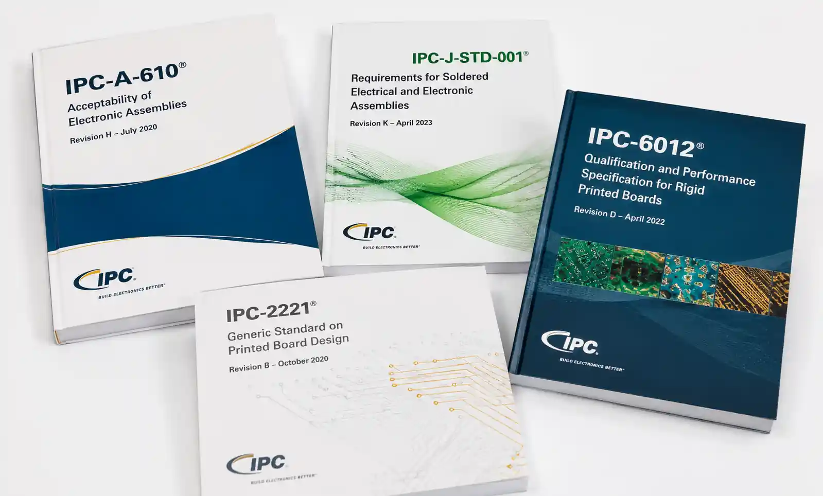
IPC-A-610 defines acceptability criteria for electronic assemblies. This is the standard assembly houses use to determine whether to ship or rework a board. It covers solder joint appearance, component placement, wire dress, hardware installation, and numerous other assembly characteristics. Most quality disputes between customers and contract manufacturers ultimately reference IPC-A-610.
IPC-J-STD-001 specifies requirements for soldering processes and materials. While IPC-A-610 shows you what an acceptable result looks like, J-STD-001 tells you how to achieve it. This standard covers hand soldering, reflow profiles, wave soldering parameters, flux selection, and cleaning requirements.
IPC-6012 establishes qualification and performance specifications for rigid printed circuit boards. It defines the tests boards must pass, the number of thermal cycles required, acceptable copper thickness ranges, and material property requirements. When you specify "IPC-6012 Class 3" on your PCB drawing, you're invoking these performance requirements.
IPC-2221 provides generic PCB design standards including conductor spacing, hole sizes, and trace width calculations. This standard helps you determine minimum clearances based on voltage levels and establishes basic design rules that work across different fabrication processes.
IPC-2581 is the modern digital data transfer format for PCB fabrication and assembly. It's gradually replacing older formats like Gerber and ODB++ by embedding intelligence about stackup, materials, netlist, and assembly information in a single XML-based file.
| Standard | Primary Focus | Typical Users | Key Sections |
|---|---|---|---|
| IPC-A-610 | Assembly acceptability | Quality inspectors, manufacturing engineers | Solder joints, component placement, cleanliness |
| IPC-J-STD-001 | Soldering requirements | Process engineers, operators | Reflow profiles, hand soldering, materials |
| IPC-6012 | Rigid PCB performance | PCB designers, procurement | Qualification testing, material specs, class levels |
| IPC-2221 | PCB design guidelines | Layout engineers, designers | Spacing rules, trace widths, hole sizes |
| IPC-2581 | Manufacturing data format | CAD engineers, CM data teams | Stackup definition, BOM, assembly data |
The distinction between acceptability standards (like A-610) and performance standards (like 6012) matters. A board can pass all IPC-A-610 visual criteria but still fail reliability testing if it wasn't manufactured to the appropriate IPC-6012 class. You need both: the performance standard ensures the board was built with adequate materials and processes, while the acceptability standard verifies the assembly was executed correctly.
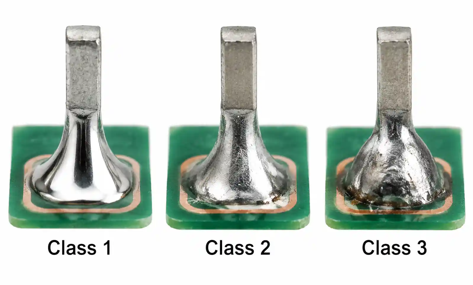
3. IPC Class Levels: Understanding Acceptance Criteria
IPC standards use a three-tier class system that defines how strict the acceptance criteria should be. The class you specify directly impacts manufacturing yield, cost, and long-term reliability.
Class 1 (General Electronic Products) includes consumer electronics and other applications where cosmetic imperfections are acceptable and the primary requirement is basic functionality. Class 1 permits solder voids up to 75% of the joint area, allows disturbed or rough solder surfaces, and accepts minor component misalignment. This class prioritizes manufacturing throughput and cost over long-term reliability.
Class 2 (Dedicated Service Electronic Products) covers most commercial and industrial electronics including computers, telecommunications equipment, and test instruments. These products require higher reliability than consumer goods but don't face the extreme conditions of military or aerospace applications. Class 2 limits solder voids to 25% of joint area, requires smooth solder surfaces without excessive texture, and tightens component placement tolerances. The vast majority of electronics manufacturing today targets Class 2.
Class 3 (High Performance Electronic Products) applies to equipment where continued performance is critical and downtime is unacceptable. This includes medical devices, aerospace avionics, military systems, and life-safety equipment. Class 3 allows minimal voids in solder joints, requires excellent wetting with full fillet formation, and specifies tight component alignment. Manufacturing yields drop significantly under Class 3 requirements, which drives higher piece prices.
Here's a comparison of how these classes affect key acceptance criteria:
| Criteria | Class 1 | Class 2 | Class 3 |
|---|---|---|---|
| Solder voids (% of joint area) | Up to 75% | Up to 25% | Minimal, <10% |
| Solder surface finish | Rough or disturbed acceptable | Smooth, minor texture OK | Smooth, bright, full wetting |
| Component tombstoning | Acceptable if electrically connected | Rework required | Not acceptable |
| Lifted leads | Acceptable if >50% contact remains | Rework if <75% contact | Rework if <100% contact |
| Solder balls/splash | Allowed if not bridging | Limited, based on spacing | Minimal, strict spacing rules |
| Flux residue | Allowed if non-corrosive | Cleaning often specified | Cleaning typically required |
The class level cascades through multiple standards. When you specify Class 3 on a PCB, you're typically invoking Class 3 requirements across IPC-6012 (board performance), IPC-A-610 (assembly acceptability), and J-STD-001 (soldering processes). Your board will undergo more thermal stress testing during qualification, your assemblies will be inspected to stricter criteria, and your processes will require tighter control.
4. How to Select the Right IPC Class for Your Application
Choosing the appropriate class level requires balancing reliability requirements against cost and schedule constraints. Over-specifying class level increases expenses without improving product performance, while under-specifying creates field reliability risks.
Start by assessing the operating environment and failure consequences. Products operating in controlled environments with easy access for repair rarely justify Class 3. A desktop computer power supply runs in a temperature-controlled office and can be swapped in minutes if it fails, making Class 2 appropriate. The same power supply design heading into a satellite requires Class 3 because repair is impossible and failure means mission loss.
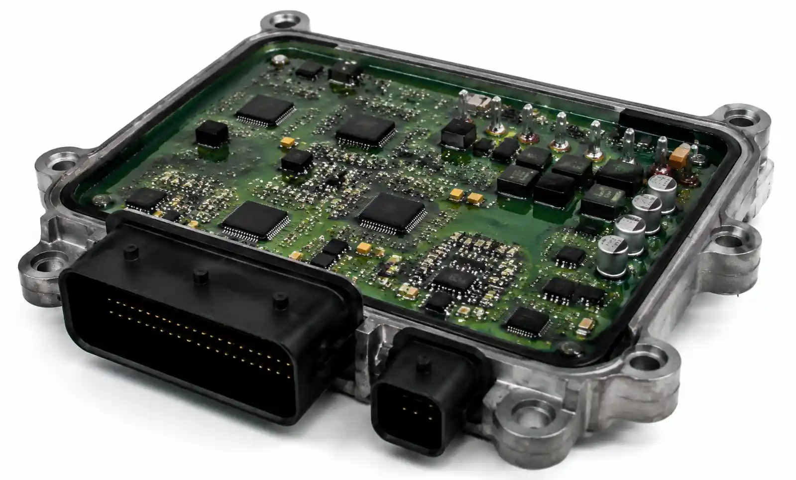
Consider the thermal and mechanical stress conditions. Equipment experiencing repeated temperature cycling, shock, or vibration benefits from the additional manufacturing margins in higher classes. A sensor module that goes through 500 thermal cycles annually in an automotive underhood application faces much harsher conditions than a wall-mounted thermostat, even though both are industrial products.
Evaluate your supply chain capabilities. Class 3 manufacturing requires specialized equipment, trained inspectors, and documented processes. Not all contract manufacturers have the capabilities or certifications to build to Class 3, which can limit your supplier options and extend lead times. If you specify Class 3, verify your manufacturing partners have relevant experience and hold appropriate certifications before committing to the design.
Factor in the cost impact. Moving from Class 2 to Class 3 typically increases PCB costs by 20-40% and assembly costs by 30-60% due to lower yields, more stringent inspection, and additional rework. For low-volume production, the per-unit cost increase might be acceptable. For high-volume consumer products, it could price you out of the market.
| Application Type | Typical Class | Key Decision Factors |
|---|---|---|
| Consumer electronics | Class 1 or 2 | Cost sensitivity, short product life, easy repair access |
| Industrial controls | Class 2 | Moderate reliability needs, controlled environment, repairable |
| Telecommunications | Class 2 or 3 | High reliability, difficult service access, long service life |
| Medical devices | Class 2 or 3 | Regulatory requirements, patient safety, continuous operation |
| Automotive (cabin) | Class 2 | Moderate temperature range, accessible for service |
| Automotive (underhood) | Class 3 | Extreme temps, vibration, difficult access, safety critical |
| Aerospace/defense | Class 3 | Mission critical, extreme conditions, impossible to service |
In practice, many products use a mixed approach: specifying Class 2 for most circuitry with Class 3 requirements for safety-critical sections. A medical infusion pump might build the user interface board to Class 2 while requiring Class 3 for the dose control circuitry. This targeted approach optimizes cost while ensuring adequate reliability where it matters most.
5. Common Implementation Challenges and Solutions
Even experienced teams encounter difficulties when implementing IPC standards. The most frequent issues involve interpretation ambiguities, measurement methods, and practical application of visual criteria.
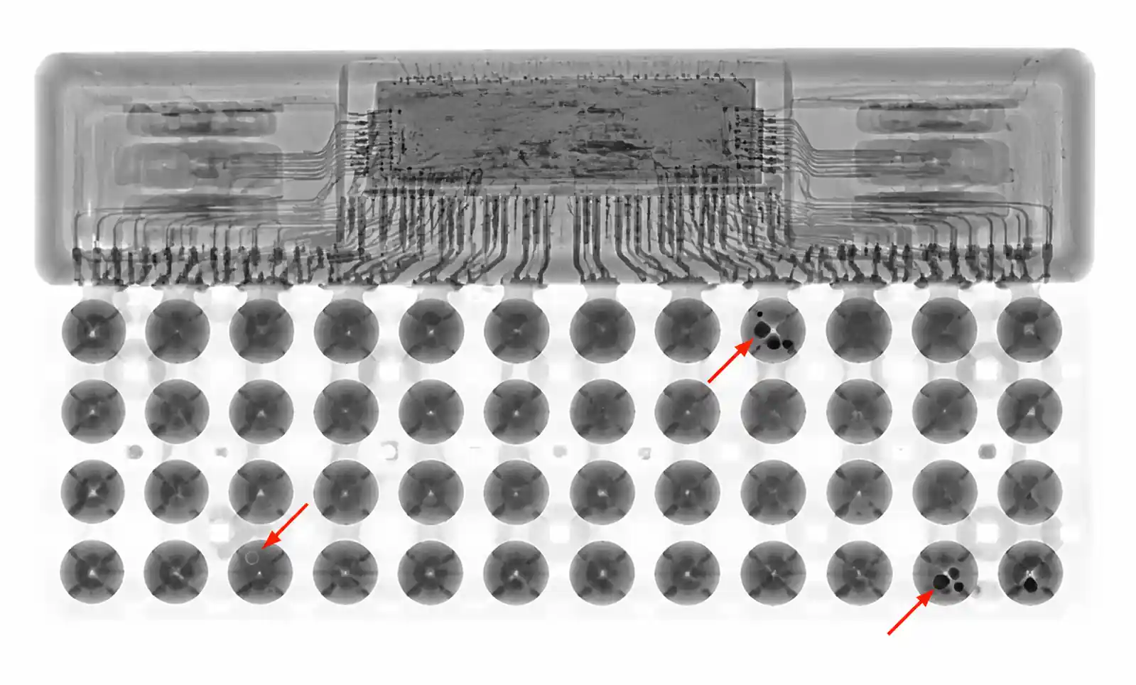
Interpretation of visual criteria causes persistent disagreements between customers and suppliers. IPC-A-610 includes photographs of acceptable and unacceptable conditions, but real-world assemblies often fall somewhere between the published examples. Solder joints that look marginal under magnification might meet the standard's dimensional requirements, while joints that appear cosmetically perfect could hide voids revealed only through X-ray inspection.
The solution involves establishing clear inspection procedures before production starts. Define the magnification level for visual inspection, specify which defects require X-ray verification, and create work instructions with your specific product examples. Many companies develop their own photographic libraries showing borderline conditions with accept/reject decisions marked. These supplementary materials reduce subjective judgment during inspection.
Measurement repeatability becomes critical under Class 3 requirements where acceptance windows narrow significantly. Solder fillet height, component standoff, and conductor spacing measurements can vary between inspectors or inspection equipment. A board that passes inspection in the morning might fail that afternoon if measured by different personnel using different techniques.
Address this through calibration and measurement system analysis. Qualify your inspection tools (microscopes, X-ray systems, calipers) at regular intervals. Run gage R&R studies to quantify measurement variation. Document specific measurement locations and techniques in your inspection procedures. For high-volume production, automated optical inspection (AOI) provides consistent measurement methodology once properly programmed.
Process control verification presents challenges when transitioning from Class 2 to Class 3 manufacturing. Class 3 requires documented evidence that processes remain in control throughout production. You need reflow profile data, solder pot temperature logs, humidity records, and storage time tracking for moisture-sensitive components.
Set up your quality system to capture this data automatically where possible. Modern reflow ovens log profile data for every board. Solder pot controllers record temperature continuously. Environmental monitors track humidity in real-time. The key is archiving this data with traceability to specific serial numbers or lot codes so you can investigate field failures months or years later.
Training and certification requirements often catch companies by surprise. IPC offers formal training and certification programs for inspectors and operators working with the standards. Many customers now require certified IPC inspectors at their contract manufacturers, particularly for Class 3 products.
Budget time and money for IPC training during project planning. A typical IPC-A-610 certification course runs three to five days and costs several thousand dollars per person. Recertification is required every two years. Factor these ongoing training costs into your manufacturing budget, especially if you work with multiple contract manufacturers who each need trained personnel.
6. Supply Chain Considerations When Specifying IPC Standards
Your choice of IPC standards and class levels directly affects supplier selection, lead times, and total cost of ownership. Understanding these supply chain implications helps you make informed specification decisions.
Most contract manufacturers readily support Class 1 and Class 2 manufacturing since these represent the bulk of commercial electronics production. Capabilities for Class 3 are more selective. Before specifying Class 3, verify that your target manufacturers hold relevant certifications (AS9100 for aerospace, ISO 13485 for medical) and have experience with similar products. Request case studies and customer references for comparable Class 3 projects.

Lead times extend for higher class levels. Class 3 boards require additional qualification testing before production release, which adds 2-4 weeks to PCB fabrication schedules. Assembly lead times increase due to lower line yields and higher rework rates. For new product introduction, plan an extra month in your schedule when working to Class 3 versus Class 2.
Material selection becomes more constrained under Class 3. Some PCB laminates that work fine for Class 2 fail the extended thermal cycling tests required for Class 3 qualification per IPC-6012. Your PCB vendor might need to switch to higher-Tg materials or thicker copper weights, both of which increase cost and potentially limit supplier options.
| Supply Chain Factor | Class 2 Impact | Class 3 Impact |
|---|---|---|
| CM supplier options | Broad availability | Limited to certified suppliers |
| PCB lead time | 2-3 weeks typical | 4-6 weeks with qualification testing |
| Assembly lead time | 1-2 weeks typical | 2-4 weeks due to inspection/rework |
| PCB cost multiplier | Baseline | 1.2-1.4x Class 2 |
| Assembly cost multiplier | Baseline | 1.3-1.6x Class 2 |
| Material selection | Standard laminates acceptable | High-Tg materials often required |
| Minimum order quantities | Flexible, can be low volume | Higher MOQs to justify setup |
Component sourcing sees indirect effects from IPC class specification. Class 3 assembly processes may restrict certain package types that are difficult to inspect or prone to handling damage. Ultra-fine-pitch BGAs with <0.5mm ball pitch become risky under Class 3 because X-ray inspection struggles to resolve individual voids. Some manufacturers avoid or surcharge these packages for Class 3 builds.
Documentation requirements scale with class level. Class 3 production generates substantial paperwork: qualification test reports, material certifications, process control charts, inspection records, and traceability documentation. Budget time for document review and approval. Establish clear data retention policies since you may need this documentation for product liability defense years after shipment.
Geographic considerations matter for specialized IPC requirements. Class 3 manufacturing capability concentrates in regions with aerospace, medical, or defense industries. If you're designing a Class 3 product, your supplier base might be limited to specific geographic areas, which affects shipping costs, tariffs, and supply chain flexibility.
7. FAQ
What is the difference between IPC-A-610 and IPC-J-STD-001?
IPC-A-610 shows what acceptable assemblies look like after manufacturing, while J-STD-001 specifies how to manufacture them. Think of A-610 as the inspection standard and J-STD-001 as the process standard. You need both: J-STD-001 to set up your soldering processes correctly, and A-610 to verify the results meet requirements.
Do I really need Class 3 for automotive applications?
It depends on the specific application and location in the vehicle. Underhood electronics exposed to extreme temperatures, vibration, and harsh chemicals typically require Class 3. Cabin electronics in controlled environments often work fine with Class 2. Consider the thermal cycling range, service access, and safety criticality when making this decision.
Can I mix IPC class levels within a single assembly?
Technically yes, but it complicates manufacturing and inspection. You can specify Class 3 for safety-critical circuits while allowing Class 2 for non-critical sections, but you must clearly identify which areas require which class on your assembly drawings. Most manufacturers prefer consistent class levels to avoid confusion during inspection.
How do I verify my contract manufacturer actually follows IPC standards?
Request copies of their IPC certifications for relevant standards. Ask to see training certificates for their inspection personnel. Conduct a pre-production audit to observe their inspection procedures. Review their quality system documentation to verify IPC standards are incorporated into work instructions. For critical projects, consider hiring a third-party inspection service.
What happens if my product fails IPC qualification testing?
You'll need to identify the root cause and implement corrective actions before resuming production. This might involve changing materials, adjusting processes, or modifying the design. Requalification testing follows the same protocol as initial qualification. Budget contingency time in your schedule for potential qualification failures, especially for Class 3 products.
Are IPC standards mandatory or voluntary?
IPC standards are voluntary industry consensus documents, not legal requirements. However, many contracts, customer specifications, and regulatory frameworks reference IPC standards, making them effectively mandatory for those applications. Medical device regulations often cite IPC standards as recognized consensus standards.
How often do IPC standards update?
Major standards typically update every 3-5 years, with amendment letters published as needed between revisions. Always verify you're working to the current revision. Some customers specify older revisions in their contracts, which can create challenges if your supply chain has moved to newer versions.
8. Conclusion
IPC standards provide the common technical language that makes electronics manufacturing possible at scale. By establishing clear, measurable criteria for PCB fabrication and assembly, these standards reduce ambiguity and enable consistent quality across different suppliers and geographic regions.
For most commercial and industrial products, IPC-6012 Class 2 for PCBs and IPC-A-610 Class 2 for assemblies offer the right balance of reliability and cost. Reserve Class 3 for applications where the operating environment is harsh, service access is difficult, or failure consequences are severe. Don't over-specify class levels based on perceived prestige or vague reliability concerns—the cost impact is real and often unnecessary.
Before finalizing your specifications, verify that your supply chain partners have the capabilities and certifications to meet your requirements. Review sample inspection reports from similar projects. Establish clear communication protocols for handling borderline conditions during inspection. The time invested in alignment before production starts will save you from costly disputes and delays later.
If you're designing a new product and need guidance on which IPC standards apply to your application, start by reviewing your operating environment, expected service life, and failure mode consequences. Download the relevant IPC standard documents, or work with experienced contract manufacturers who can advise on appropriate class levels based on similar products they've built successfully.