


Micro Push-to-Release Wire-to-Board Connectors: Structure, Working Principle, and Engineering Selection Guide
Micro push-to-release wire-to-board connectors are engineered for compact, high-reliability electrical interconnections between discrete wires and printed circuit boards (PCBs). By leveraging spring-clamp contact technology and tool-free actuation, these connectors significantly improve assembly efficiency, reduce maintenance complexity, and ensure stable electrical performance under vibration and thermal stress. This article provides a detailed engineering analysis of their structure, working mechanism, performance characteristics, selection criteria, and comparison with conventional connection methods.
Catalog
- 1. Introduction to Micro Push-to-Release Connectors
- 2. Internal Structure and Contact Mechanism
- 3. Working Principle and Electrical Behavior
- 4. Engineering Advantages and Performance Analysis
- 5. Application Scenarios in Modern Electronics
- 6. Installation Process and Best Practices
- 7. Connector Selection Criteria
- 8. Common Failure Modes and Design Mistakes
- 9. Comparison with Other Wire-to-Board Technologies
- 10. Conclusion
- 11. FAQ
1. Introduction to Micro Push-to-Release Connectors
Micro push-to-release wire-to-board connectors are compact interconnect devices designed to terminate discrete wires directly onto PCB-mounted connectors using an integrated spring-clamp mechanism.
Unlike crimped or soldered solutions, these connectors eliminate permanent bonding and specialized tooling. The design enables:
- Direct wire insertion
- Consistent contact force
- Reversible connection without mechanical damage
From an engineering perspective, they address three critical challenges in modern electronics:
- Miniaturization constraints in high-density PCBs
- Assembly efficiency in mass production
- Maintainability in field-serviceable systems
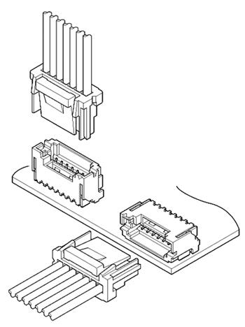
2. Internal Structure and Contact Mechanism
Key Structural Elements
- Spring clamp (stainless steel or copper alloy)
- Conductive contact surface (tin/gold plated copper alloy)
- Push actuator (plastic or metal)
- Insulating housing (typically high-temperature thermoplastic)
- PCB solder terminals
Engineering Insight
The core innovation lies in the spring clamp geometry, which ensures:
- Constant normal force across conductor surface
- Compensation for thermal expansion and vibration
- Reduced contact resistance variability
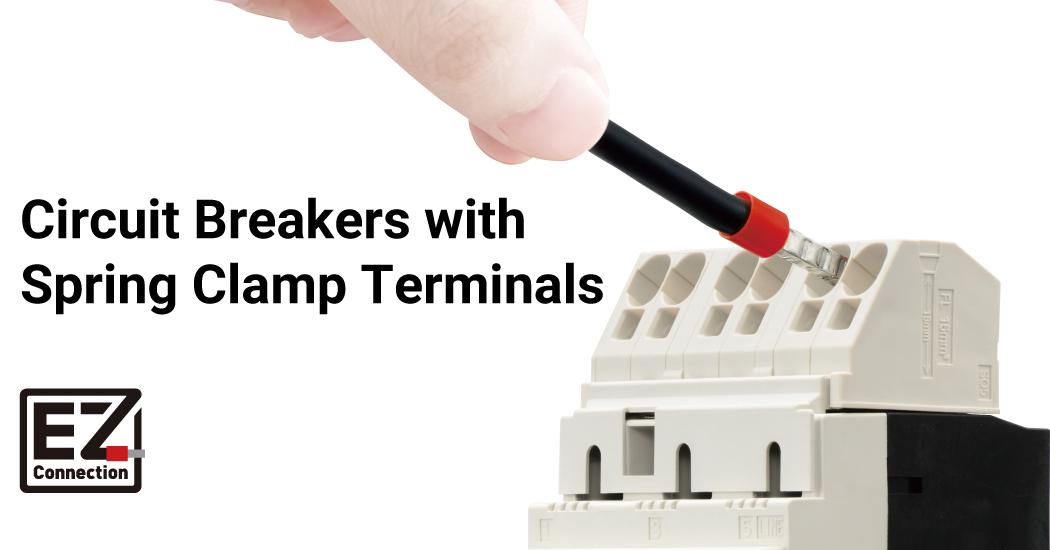
3. Working Principle and Electrical Behavior
The connector operates based on elastic deformation of a preloaded spring element.
Connection Process
- Stripped wire enters contact cavity
- Spring deflects and stores mechanical energy
- Spring presses conductor against contact interface
- Electrical path is established with low resistance
Release Process
- Actuator mechanically disengages spring force
- Contact pressure is removed
- Wire can be extracted without stress damage
Electrical Characteristics
- Contact resistance: typically < 10 mΩ
- Stable impedance under vibration
- Minimal micro-arcing due to constant pressure
4. Engineering Advantages and Performance Analysis
4.1 Contact Reliability
Spring-based systems outperform screw terminals by:
- Eliminating torque variability
- Maintaining pressure over lifecycle
- Preventing loosening under vibration
4.2 Assembly Efficiency
- Tool-free installation reduces assembly time by up to 50%
- No crimp quality variability
- Suitable for automated or semi-automated assembly lines
4.3 Mechanical and Environmental Robustness
- مقاوم to vibration (industrial/automotive use)
- مقاوم to thermal cycling
- Corrosion-resistant plating options
4.4 Space Optimization
- Ultra-compact pitch (often < 2.5 mm)
- Enables high-density PCB layouts
5. Application Scenarios in Modern Electronics
Consumer Electronics
- Wearables
- Smart home devices
- Portable systems
Industrial Systems
- PLC control panels
- Sensor interfaces
- Robotics
Automotive Electronics
- ECU modules
- Battery management systems
- ADAS sensors
Medical Devices
- Monitoring equipment
- Diagnostic modules
6. Installation Process and Best Practices
Standard Procedure
- Strip wire to specified length (typically 6–8 mm)
- Insert wire until mechanical stop
- Perform pull-test validation
- Use actuator for removal
Best Practices
- Use ferrules for stranded wires in critical systems
- Maintain correct strip length tolerance
- Avoid repeated insertion cycles beyond rated limits
7. Connector Selection Criteria
Electrical Parameters
- Rated current (e.g., 2A–10A typical)
- Voltage rating
- Contact resistance
Mechanical Parameters
- Wire gauge range (e.g., AWG 24–18)
- Retention force
- Actuation durability
Environmental Considerations
- Operating temperature range
- Humidity and corrosion resistance
- Vibration tolerance
PCB Design Factors
- Pitch spacing
- Mounting type (SMT vs THT)
- Thermal dissipation capability
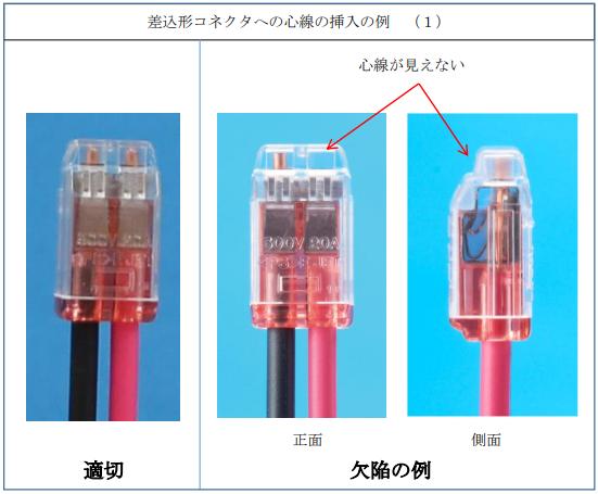
8. Common Failure Modes and Design Mistakes
Frequent Issues
- Incorrect wire gauge selection
- Insufficient strip length
- Partial insertion
- Excessive mechanical stress on wires
Engineering Risks
- Increased contact resistance
- Intermittent connection
- Thermal hotspots
- Long-term fatigue failure
9. Comparison with Other Wire-to-Board Technologies
| Feature | Push-to-Release | Crimp | Screw Terminal | Solder |
|---|---|---|---|---|
| Installation | Tool-free | Requires tool | Manual | Requires soldering |
| Maintenance | Excellent | Moderate | Moderate | Poor |
| Reliability | High | High | Medium | Very High |
| Reusability | High | Low | Medium | None |
| Application | Compact electronics | Wire harness | Industrial | Permanent |
10. Conclusion
Micro push-to-release wire-to-board connectors represent a significant advancement in PCB interconnection technology. Their spring-clamp architecture ensures consistent electrical performance while enabling rapid, tool-free installation and maintenance.
From an engineering standpoint, they are particularly well-suited for:
- High-density PCB designs
- Modular systems requiring serviceability
- Applications exposed to vibration or thermal variation
When properly selected and implemented, these connectors enhance system reliability, reduce lifecycle cost, and streamline both manufacturing and field maintenance.
11. FAQ
Q1: Are push-to-release connectors suitable for high-current applications?
They are typically designed for low-to-medium current ranges. For high-current systems, verify rated specifications or consider power-specific connectors.
Q2: Can stranded wires be used reliably?
Yes, but using ferrules is recommended to ensure uniform contact and prevent strand deformation.
Q3: How many insertion cycles are supported?
Most designs support hundreds of cycles, but this depends on material quality and spring design.
Q4: Do these connectors perform well under vibration?
Yes. The constant spring force maintains stable contact, making them suitable for automotive and industrial environments.
Q5: Are they better than soldering?
They are not a replacement for permanent connections but provide superior flexibility, serviceability, and installation speed.