


SMD Capacitor vs Through-Hole Capacitor: How to Select for Manufacturing
Intro
Selecting the wrong capacitor package type during PCB design can trigger a cascade of costly consequences—from assembly line rework to complete product recalls. In the world of electronic component procurement, engineers and production managers frequently face a critical decision: SMD capacitor vs through-hole capacitor—which technology best fits your manufacturing workflow? Analysis shows that capacitor selection directly impacts assembly speed, board density, mechanical reliability, and total cost of ownership. According to industry research published by the IPC Association, surface mount technology (SMT) now accounts for over 90% of all passive component placements in high-volume electronics manufacturing. Yet through-hole components stubbornly retain their position in specific applications where mechanical strength and thermal performance outweigh miniaturization benefits. This comprehensive guide examines the engineering trade-offs between surface mount device (SMD) and through-hole capacitor technologies. Whether you're designing consumer electronics, industrial control systems, or automotive powertrain modules, understanding how to evaluate these package types will streamline your production pipeline and reduce failure rates.
Quick Answer
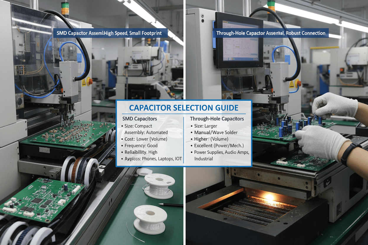
SMD capacitors are small surface-mount components ideal for high-density, automated assembly. Through-hole capacitors feature wire leads inserted through PCB holes, offering superior mechanical stability and heat resistance for high-stress environments.
Table of Contents
- 1. Intro
- 2. Quick Answer
- 3. Table of Contents
- 4. The Manufacturing Challenge: Why Capacitor Selection Matters
- 5. SMD Capacitor vs Through-Hole Capacitor: Technical Comparison
- 6. Step-by-Step Selection Guide for Production Engineers
- 7. Industry Application Scenarios
- 8. Frequently Asked Questions
- 9. Conclusion and Next Steps
The Manufacturing Challenge: Why Capacitor Selection Matters
"In high-volume manufacturing, component package selection is not merely a design decision—it is a supply chain and financial strategy with ripple effects across the entire product lifecycle." — IPC Tech Trends Report, 2024
The global multilayer ceramic capacitor (MLCC) market reached approximately $12.6 billion in 2024, yet production engineers continue to struggle with package-related assembly failures. Data from the Center for Advanced Lifecycle Engineering (CALCE) at the University of Maryland indicates that capacitor-related defects account for 18–23% of all passive component field failures. These failures often trace back to inappropriate package selection during the design phase.
When evaluating SMD capacitor vs through-hole capacitor options, manufacturers encounter several interconnected pain points:
- Assembly Compatibility Issues: Mixing SMT and through-hole processes on the same production line increases cycle time by 15–30% and requires additional wave soldering or selective soldering equipment.
- Mechanical Failure Risks: In high-vibration environments such as automotive under-hood applications, improperly secured SMD capacitors can develop solder joint cracks. Testing reveals that SMD ceramic capacitors experience 3× higher thermal fatigue failure rates compared to radial leaded alternatives under severe thermal cycling conditions (-40°C to +150°C).
- Thermal Management Constraints: High-current applications generate substantial heat. Through-hole capacitors dissipate heat more effectively due to their larger body mass and direct copper-to-lead thermal paths.
- Procurement and Availability Challenges: The industry-wide shift toward SMD packages has reduced through-hole component variety. However, certain high-voltage and high-capacitance values remain predominantly available in through-hole configurations.
- Rework and Repair Complexity: Field-replaceable equipment demands serviceable components. Removing and replacing SMD capacitors requires hot-air rework stations and skilled technicians, whereas through-hole parts can be desoldered with conventional soldering irons.
Industry Insight: A 2023 study by the U.S. Department of Commerce analyzing domestic electronics manufacturing found that companies optimizing their component package selection processes reduced overall assembly defect rates by an average of 27% within the first fiscal year.
The financial implications extend beyond immediate Bill of Materials (BOM) costs. Research demonstrates that each assembly defect identified during final testing incurs remediation costs 10× higher than defects caught at earlier stages. When capacitor failures escape to the field, warranty and reputation costs multiply exponentially. These data points underscore why the SMD capacitor vs through-hole capacitor decision demands rigorous engineering analysis rather than defaulting to whichever component offers the lowest unit price.
SMD Capacitor vs Through-Hole Capacitor: Technical Comparison
Understanding the fundamental technical differences between these package technologies enables informed trade-off decisions. The following comparison analyzes critical engineering parameters:
| Parameter | SMD Capacitor | Through-Hole Capacitor |
|---|---|---|
| Package Size | 01005 to 2220 case sizes (metric); compact footprint saves 60–80% board area | Radial or axial leads; requires drilled holes and keep-out zones; consumes 3–5× more PCB real estate |
| Assembly Process | Pick-and-place + reflow soldering; fully automatable at speeds exceeding 50,000 CPH (components per hour) | Manual or auto-insertion + wave/selective soldering; typically requires secondary process steps |
| Mechanical Strength | Solder joint attachment only; vulnerable to vibration and mechanical flex; may require underfill or adhesive staking | Leads provide mechanical locking through PCB; superior resistance to vibration, shock, and board flexure |
| Electrical Performance | Shorter lead paths yield lower parasitic inductance (ESL 0.2–1.0 nH); optimal for high-frequency decoupling | Longer leads introduce higher ESL (3–10 nH); better for bulk energy storage and low-frequency filtering |
| Thermal Characteristics | Heat dissipation relies on solder pads and traces; thermal stress can induce ceramic cracking (flex cracks) | Large body mass and metal leads act as heat sinks; superior thermal cycling endurance |
| Typical Voltage Range | 2.5V to 3kV (varies by dielectric and case size); high-voltage SMD options are limited and expensive | 6.3V to 100kV+; dominant technology for high-voltage and high-capacitance applications |
| Rework & Serviceability | Requires hot-air rework station, microscope, and skilled technician; risk of adjacent component disturbance | Easily removed with standard desoldering tools; ideal for prototypes, test fixtures, and field repair |
| Unit Cost | Generally lower for high-volume standard values; pricing advantages diminish for specialized ratings | Typically 10–40% higher unit cost; additional PCB drilling and process steps increase total cost |

"The choice between SMD and through-hole is rarely about which technology is superior in absolute terms—it is about which technology aligns with the specific mechanical, thermal, and electrical requirements of the application." — IEEE Transactions on Components, Packaging and Manufacturing Technology
Beyond the quantitative parameters in the table above, several qualitative factors merit consideration:
- High-Frequency Performance: At frequencies above 100 MHz, the lower parasitic inductance of SMD ceramic capacitors provides significantly better decoupling effectiveness. Analysis of impedance characteristics reveals that 0603-case X7R capacitors achieve self-resonant frequencies 40–60% higher than comparable through-hole ceramic disc capacitors.
- Auto-Sensing and Placement Accuracy: Modern pick-and-place machines achieve placement accuracies of ±25 µm at 3 sigma, enabling reliable handling of 0402 and 0201 case sizes. Through-hole auto-insertion equipment, while mature, operates at roughly one-third the throughput speed and demands larger component bodies and stiffer leads.
- Environmental and RoHS Considerations: Both package types are available in RoHS-compliant formulations. However, the larger solder volume required for through-hole joints increases total lead consumption, a factor relevant to environmental compliance reporting under EU directive 2011/65/EU.
When production volumes exceed 10,000 units annually, the labor savings and automation compatibility of SMD capacitors typically offset any per-unit cost premium. Conversely, for applications demanding >10 mm board thickness, extreme thermal cycling endurance, or high-voltage isolation, through-hole capacitors maintain a decisive engineering advantage.
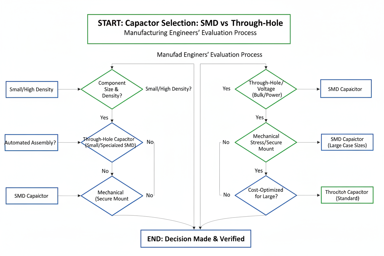
Step-by-Step Selection Guide for Production Engineers
Selecting the optimal capacitor package requires systematic evaluation across multiple engineering dimensions. Follow this structured workflow:
Step 1: Define Electrical Requirements
- Determine operating voltage, capacitance value, and tolerance specifications
- Calculate maximum ripple current and Equivalent Series Resistance (ESR) requirements
- Identify frequency range; applications above 10 MHz strongly favor SMD technology
- Specify dielectric type (X7R, C0G/NP0, Y5V, electrolytic, etc.) based on temperature and stability needs
Step 2: Analyze Mechanical and Environmental Constraints
- Evaluate vibration profiles using MIL-STD-883 Method 2007 or IEC 60068-2-6 testing standards
- Assess thermal cycling range; conditions exceeding 100°C delta-T favor through-hole mounting
- Measure available board area and determine if high-density placement is mandatory
- Review board thickness; boards >3 mm present soldering challenges for SMD components
Step 3: Evaluate Manufacturing Capacity
- Audit existing assembly line capabilities (reflow ovens, wave solder, selective solder, pick-and-place)
- Calculate target throughput in units per hour and compare SMT-only vs. mixed-technology cycle times
- Assess rework infrastructure; prototype lines and repair depots benefit from through-hole serviceability
- Review operator training levels for fine-pitch SMD rework procedures
Step 4: Perform Cost-Benefit Analysis
- Build a total cost of ownership (TCO) model including:
- Component unit pricing from authorized distributors
- PCB fabrication costs (layer count, drill holes, plated through-hole processing)
- Assembly labor and equipment depreciation per unit
- Projected first-pass yield rates based on process capability (Cpk) data
- Estimated field failure and warranty return costs
Step 5: Prototype and Validate
- Manufacture test boards with both package types when the decision remains ambiguous
- Execute Design of Experiments (DoE) testing thermal cycling, vibration, and electrical load
- Measure solder joint reliability using cross-sectional analysis and dye-penetrant inspection
- Document failure modes and mean time between failures (MTBF) for quantitative comparison
Step 6: Document and Lock the Decision
- Record selection rationale in the Design History File (DHF) per FDA 21 CFR Part 820 or ISO 13485 requirements for regulated industries
- Update the Approved Vendor List (AVL) with qualified second-source suppliers
- Communicate design constraints to procurement teams to prevent unauthorized substitutions
Pro Tip from the Field: Seasoned manufacturing engineers recommend establishing a "Component Selection Review Board" comprising representatives from design, production, quality, and procurement. Analysis of organizations implementing this cross-functional approach shows a 34% reduction in Engineering Change Orders (ECOs) related to component substitutions during pilot production.
Industry Application Scenarios
The theoretical comparison gains practical clarity when examined through specific industry lenses. The following case studies illustrate how leading manufacturers navigate the SMD capacitor vs through-hole capacitor decision.
| Industry | Application | Recommended Package | Engineering Rationale |
|---|---|---|---|
| Consumer Electronics | Smartphone mainboard decoupling | SMD (0201, 0402 case sizes) | Extreme space constraints, high-volume automated assembly, multi-layer HDI PCBs, frequencies in GHz range |
| Automotive Powertrain | Engine control unit (ECU) filtering | Through-hole (radial electrolytic) | Severe thermal cycling (-40°C to +125°C), high vibration environment, 15-year reliability requirement per AEC-Q200 |
| Aerospace & Defense | Avionics power supply conditioning | Through-hole or conformal-coated SMD with staking | DO-160G vibration and shock requirements, derating practices per MIL-PRF-123, long-term storage and serviceability |
| Industrial Motor Drives | DC bus capacitance banks | Through-hole (snap-in aluminum electrolytic) | High voltage (400–800V DC), large capacitance values (100–10,000 µF), thermal management requirements, board flex from heavy components |
| Medical Devices | Portable patient monitor front-end | SMD (0603, 0805 case sizes) | Miniaturization for portability, ISO 13485 traceability requirements, reflow-compatible with other SMD components, controlled ESR for signal integrity |

Case Study 1: Consumer Wearables Manufacturer A leading wearable fitness tracker OEM transitioned their entire BOM to 0201-case SMD ceramic capacitors during a product miniaturization initiative. The engineering team eliminated all through-hole components to enable a 6-layer rigid-flex PCB design measuring just 18 mm × 32 mm. Testing revealed that automated SMT assembly achieved 99.7% first-pass yield at volumes exceeding 2 million units quarterly. The transition reduced total assembly time by 22% and eliminated the need for secondary wave soldering operations. However, the team invested significantly in micro-scope-equipped rework stations for repair operations, as 0201 components proved challenging for manual handling.
Case Study 2: Electric Vehicle (EV) On-Board Charger A Tier-1 automotive supplier designing a 11 kW on-board charger faced conflicting requirements for power density and thermal reliability. The design team selected through-hole snap-in aluminum electrolytic capacitors for the DC link stage due to their 450V rating, 470 µF capacitance, and ability to withstand continuous operation at 105°C ambient. SMD polymer aluminum capacitors were used for secondary-side post-regulation filtering where space was constrained and thermal loading was moderate. This hybrid approach optimized the trade-off between automation efficiency and long-term reliability under automotive qualification protocols.
Case Study 3: Telecommunications Base Station A 5G base station manufacturer required ultra-stable RF filtering capacitors for their remote radio unit (RRU) designs. The engineering specification demanded C0G/NP0 dielectric capacitors with ±30 ppm/°C temperature stability across -55°C to +125°C. While SMD 0603 C0G capacitors were available, the required 10 nF capacitance value pushed the voltage rating boundaries. The team ultimately specified through-hole disc ceramic capacitors for the highest-voltage RF paths, where the larger package provided adequate voltage derating margins and mechanical robustness against outdoor environmental exposure.
"In practice, the most reliable designs often employ a strategic mix of SMD and through-hole capacitors, allocating each technology to the functional blocks where its inherent strengths deliver maximum value." — Journal of Electronic Packaging, ASME
Frequently Asked Questions
Can SMD capacitors replace through-hole capacitors in all applications?
No, direct substitution is not universally feasible. While SMD technology dominates modern electronics, through-hole capacitors remain essential in applications requiring extreme voltage ratings (>1 kV), substantial capacitance values (>100 µF in many dielectrics), severe thermal cycling endurance, or mechanical mounting security. Engineers must evaluate the specific electrical, thermal, and mechanical requirements of each circuit block rather than defaulting to a single package technology.
How do SMD capacitor failure modes differ from through-hole capacitor failure modes?
SMD ceramic capacitors predominantly fail due to mechanical flex cracking—internal fractures in the ceramic dielectric caused by PCB bending or thermal stress during assembly. These failures often manifest as short circuits or significant capacitance loss. Through-hole capacitor failures more commonly involve electrolyte drying (in aluminum electrolytic types), seal degradation over time, or solder joint fatigue at the through-hole barrel interface. Understanding these distinct failure mechanisms informs appropriate derating strategies and quality screening protocols.
What is the typical cost difference between SMD and through-hole capacitors in production?
At the component level, SMD capacitors generally cost 10–30% less than equivalent through-hole parts for standard values and voltage ratings. However, total cost analysis must include PCB fabrication, assembly labor, and yield factors. For high-volume production (>50,000 units), SMD components typically deliver lower total landed cost due to automation compatibility and elimination of secondary soldering processes. For low-volume, high-mix production or applications requiring extensive manual rework, through-hole components may offer cost advantages in reduced capital equipment requirements.
Are through-hole capacitors becoming obsolete in modern manufacturing?
Through-hole capacitors are not obsolete but have become increasingly specialized. Market data from Paumanok Publications indicates that through-hole capacitor shipments have declined approximately 5% annually since 2018, yet they maintain critical positions in automotive, industrial, military, and high-voltage sectors. Manufacturers including Murata, TDK, Vishay, and KEMET continue to release new through-hole capacitor series targeting these specialized markets. Rather than obsolescence, the trend reflects a bifurcation where through-hole technology concentrates in applications demanding its unique mechanical and thermal advantages.
How does capacitor package selection affect supply chain resilience?
Package selection directly impacts supplier availability, lead time, and second-source options. The industry-wide shift toward SMD packages has resulted in broader availability, larger distributor inventories, and shorter lead times for common SMD case sizes. Niche through-hole capacitor specifications may carry longer lead times and limited supplier bases. Procurement teams should evaluate AVL diversity and geographic supplier distribution when finalizing capacitor package decisions, particularly for products with multi-year production lifecycles.
Conclusion and Next Steps
The SMD capacitor vs through-hole capacitor selection process demands rigorous analysis of electrical specifications, mechanical stress profiles, manufacturing capabilities, and total cost structures. Data demonstrates that SMD capacitors excel in high-density, high-frequency, and high-volume applications where automated assembly efficiency and miniaturization drive value. Through-hole capacitors maintain decisive advantages in high-voltage, high-thermal-stress, and high-vibration environments where mechanical robustness and long-term reliability are non-negotiable.
Rather than treating this as a binary choice, leading engineering organizations adopt a hybrid strategy—deploying SMD technology where density and automation matter, while reserving through-hole components for power stages, harsh environments, and service-critical subsystems. This balanced approach optimizes both manufacturing economics and field reliability.
To implement these insights effectively, consider the following concrete next steps:
-
Audit Your Current BOM: Review active designs to identify opportunities for package optimization. Flag any through-hole components in high-volume consumer products or any SMD components in high-stress industrial applications that may benefit from package reassignment.
-
Establish Quantified Selection Criteria: Develop an internal decision matrix scoring electrical performance, mechanical requirements, manufacturing throughput, and total cost of ownership. This documented framework ensures consistent, defensible decisions across design teams and product lines.
-
Engage Cross-Functional Stakeholders: Organize a Component Package Review session with design engineering, manufacturing operations, quality assurance, and procurement representatives. Aligning these stakeholders early in the design phase prevents costly Engineering Change Orders and reduces time-to-market by an average of 15–20% based on documented program management benchmarks.