


2-Pin vs 4-Pin Button Switch: Structural, Electrical, and Application-Level Differences
Push button switches are fundamental electromechanical components used for human-machine interaction in electronic systems. While 2-pin and 4-pin button switches often appear functionally equivalent, their internal topology, PCB integration behavior, and reliability characteristics differ significantly. This article provides a concise yet in-depth engineering analysis covering structure, electrical operation, wiring logic, reliability considerations, and practical selection criteria to support robust circuit design.
Table of Contents
- 1. Fundamentals of Button Switches
- 2. Structural Differences: 2-Pin vs 4-Pin
- 3. Electrical Working Principle
- 4. Wiring Topology and PCB Integration
- 5. Mechanical Reliability and Contact Performance
- 6. Testing and Fault Diagnosis
- 7. Selection Criteria for Engineering Applications
- 8. Typical Application Scenarios
- 9. FAQ
- 10. Conclusion
1. Fundamentals of Button Switches
A button switch is a momentary or latching electromechanical device that controls current flow through physical actuation. Most small-form-factor switches used in embedded systems are momentary normally-open (NO) types.
Key parameters:
- Contact resistance (typically <100 mΩ)
- Rated voltage/current
- Mechanical life cycle (e.g., 100k–1M actuations)
- Actuation force (gf range)
2. Structural Differences: 2-Pin vs 4-Pin
2.1 2-Pin Switch Structure
- Single conductive path
- Two terminals directly connected via movable contact
- Minimal mechanical support
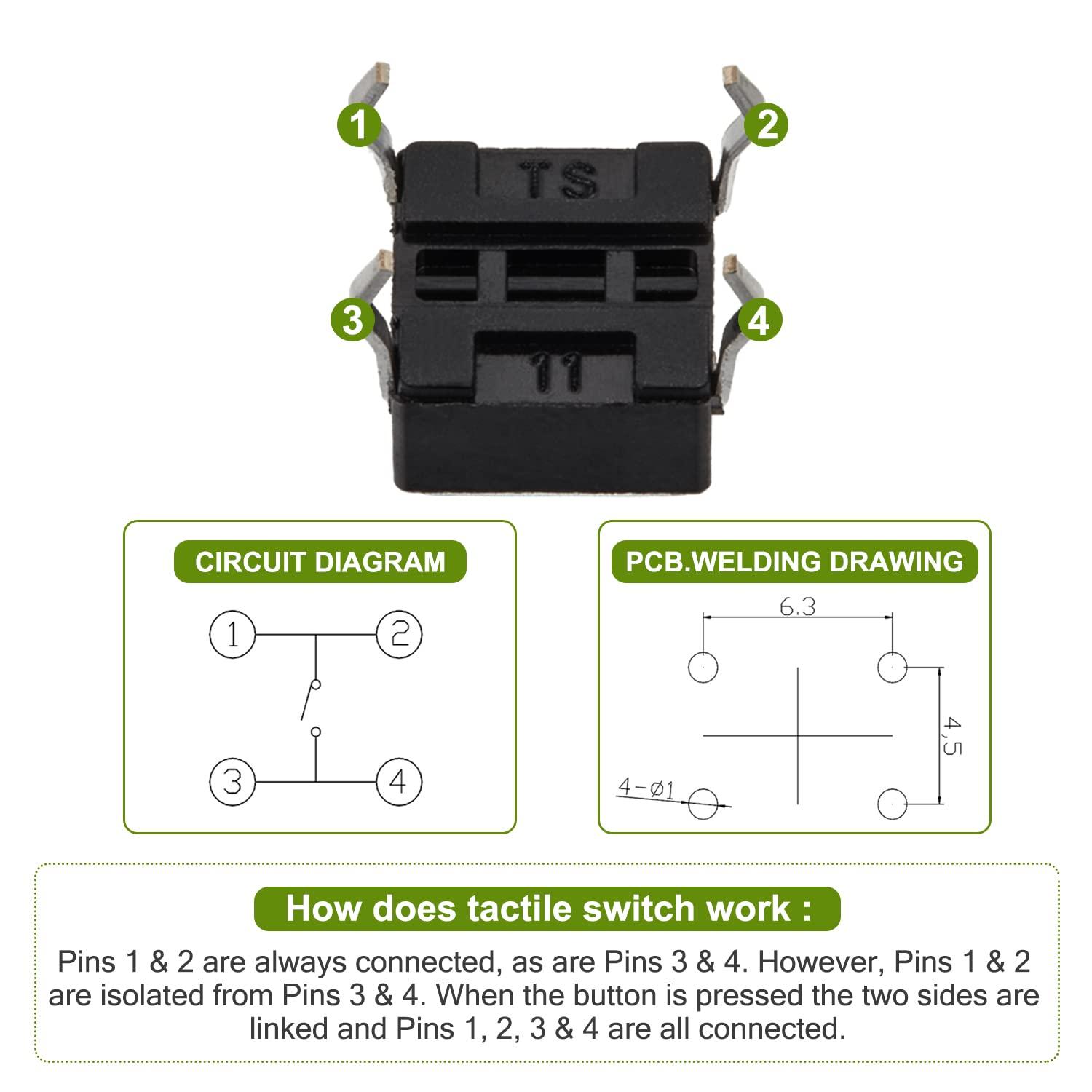
2.2 4-Pin Switch Structure
- Internally organized as two electrically common pairs
- Cross-connection occurs only during actuation
- Provides mechanical anchoring + redundant contact paths
Engineering Insight
4-pin switches are not “double circuits” — they are mechanically duplicated terminals for the same node pairs, improving:
- PCB stability
- Solder joint reliability
- Contact consistency
3. Electrical Working Principle
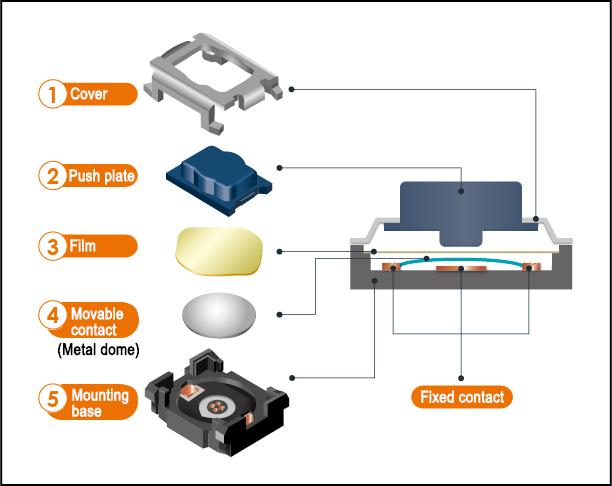
3.1 2-Pin Operation
- Open state: circuit interrupted
- Pressed state: metal dome bridges terminals
- Single current path
3.2 4-Pin Operation
- Two pins per node (Node A and Node B)
- Pressing creates a bridge between node groups
- Electrically equivalent to SPST switch
Contact Physics Consideration
- Contact bounce (5–20 ms typical)
- Requires debouncing in digital circuits (hardware RC or firmware filtering)
4. Wiring Topology and PCB Integration
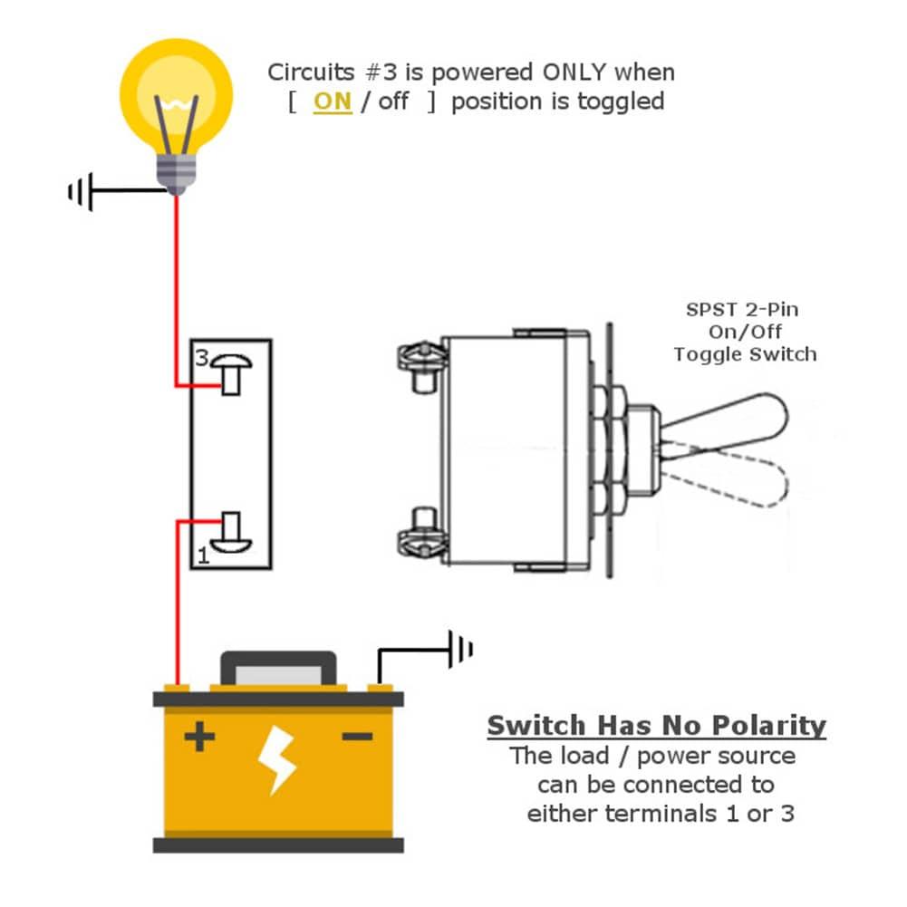
4.1 2-Pin Wiring
- Straightforward series connection
- Minimal routing complexity
- Suitable for:
- Breadboards
- Point-to-point wiring
4.2 4-Pin Wiring (Critical Detail)
- Identify internal pairs (usually aligned horizontally or vertically)
- Use one pin from each pair
Incorrect wiring failure mode:
- Using same-pair pins → permanent short (no switching behavior)
PCB Design Implications
| Factor | 2-Pin | 4-Pin |
|---|---|---|
| Footprint stability | Low | High |
| Solder joint redundancy | No | Yes |
| Routing flexibility | Limited | Flexible |
| Mechanical stress resistance | Weak | Strong |
5. Mechanical Reliability and Contact Performance
5.1 Mechanical Stability
- 2-pin: prone to tilt, stress concentration at pads
- 4-pin: distributed force → improved durability
5.2 Contact Reliability
- Multi-point support in 4-pin reduces:
- Micro-misalignment
- Uneven wear
5.3 Lifecycle Engineering
- 4-pin switches typically achieve higher actuation consistency over lifecycle
- Preferred for:
- High-frequency input devices
- Industrial HMIs
6. Testing and Fault Diagnosis
6.1 Multimeter Testing Procedure
Mode: Continuity / Resistance
2-Pin
- Open (unpressed): OL
- Pressed: ~0 Ω
4-Pin
- Identify internally shorted pairs
- Test across opposite pairs
- Press to verify conduction
6.2 Common Faults
- Contact oxidation → increased resistance
- Mechanical fatigue → intermittent failure
- Solder cracks (more common in 2-pin designs)
7. Selection Criteria for Engineering Applications
7.1 Electrical Requirements
- Voltage/current margin ≥ 20–30%
- Consider inrush current for capacitive loads
7.2 Mechanical Integration
- PCB-mounted → prefer 4-pin
- Hand-wired → 2-pin sufficient
7.3 Environmental Constraints
- IP-rated switches for:
- Dust
- Moisture
- Operating temperature range
7.4 Human Factors
- Tactile feedback force
- Travel distance
- Ergonomic consistency
8. Typical Application Scenarios
8.1 2-Pin Switch Use Cases
- Prototyping (breadboards)
- Simple ON/OFF control
- Low-duty-cycle devices
8.2 4-Pin Switch Use Cases
- Keypads and keyboards
- Microcontroller inputs (e.g., GPIO triggers)
- Consumer electronics
- Industrial control panels
9. FAQ
Q1: Are 4-pin switches electrically different from 2-pin?
No. Electrically, both are typically SPST momentary switches. The extra pins are for mechanical and layout advantages, not additional switching paths.
Q2: Why does my 4-pin switch always show continuity?
You are likely probing pins from the same internal pair, which are permanently connected.
Q3: Do I always need a 4-pin switch for PCB design?
Not always. Use 4-pin when:
- Mechanical stability matters
- Repeated actuation is expected
Q4: How to handle switch bounce?
Use:
- RC debounce circuit
- Software debounce (e.g., 10–20 ms delay window)
Q5: Can 4-pin switches support LEDs?
Some variants integrate LEDs, but this is not inherent to the 4-pin structure.
10. Conclusion
From an engineering standpoint, the distinction between 2-pin and 4-pin button switches lies not in their fundamental electrical behavior, but in mechanical robustness, PCB integration, and long-term reliability.
- Use 2-pin switches for simplicity and rapid prototyping
- Use 4-pin switches for production-grade, PCB-mounted systems
Correct selection improves not only functionality but also manufacturability, durability, and user experience—all critical factors in professional electronic design.