


Bolt-On Circuit Breakers: Design, Operation, and Engineering Selection Guide
Bolt-on circuit breakers are widely used in commercial and industrial power distribution systems due to their superior mechanical fastening and stable electrical contact. Unlike plug-in designs, bolt-on breakers are secured directly to the busbar, minimizing contact resistance and improving long-term reliability. This article provides a detailed engineering-level analysis of their structure, working principles, comparison with other breaker types, selection methodology, and failure diagnostics to support safe and optimized system design.
Table of Contents
- 1. Fundamentals of Bolt-On Circuit Breakers
- 2. Internal Working Principle
- 3. Bolt-On vs Plug-In vs Screw-In Breakers
- 4. Types of Bolt-On Circuit Breakers
- 5. Engineering Selection Criteria
- 6. Installation and Torque Considerations
- 7. Failure Modes and Troubleshooting
- 8. Key Features and Performance Advantages
- 9. FAQ
- 10. Conclusion
1. Fundamentals of Bolt-On Circuit Breakers
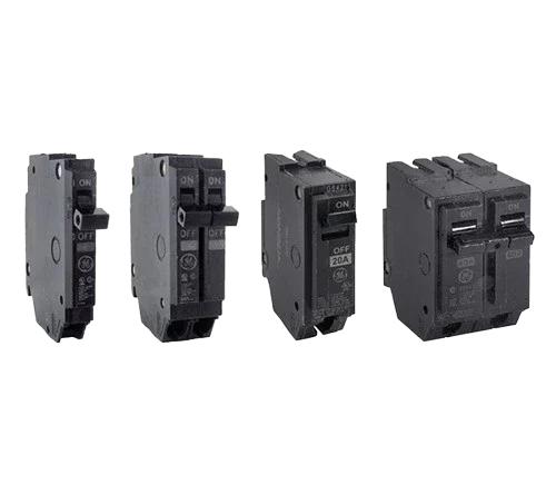
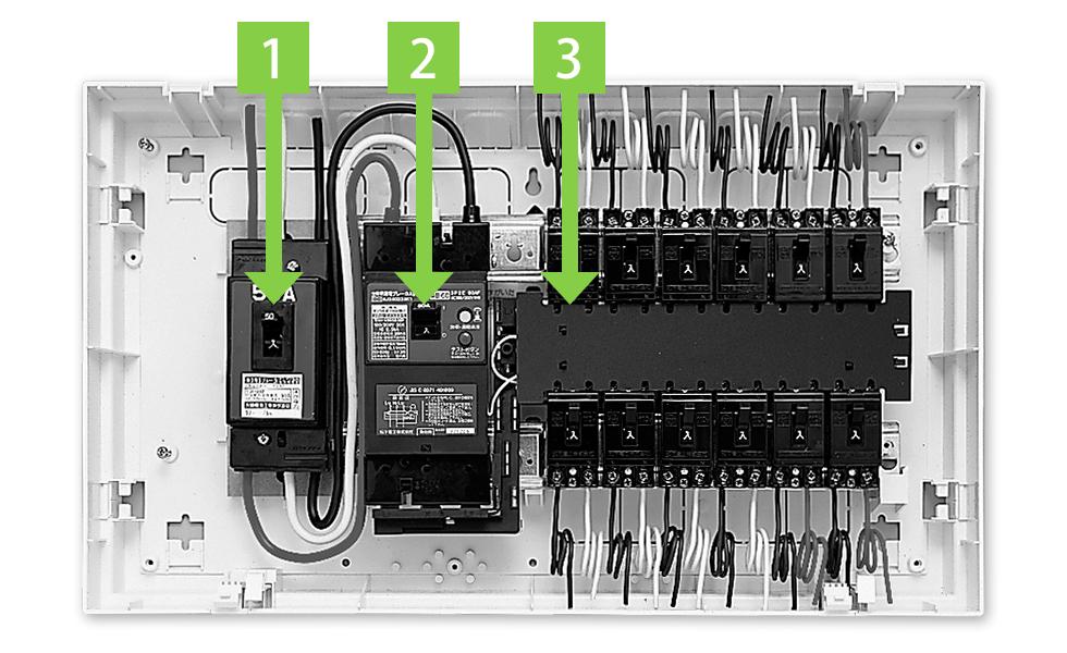
A bolt-on circuit breaker is a low-voltage protective device mechanically fastened to a panelboard busbar using screws or bolts. This fastening method creates a high-integrity electrical interface compared to spring-contact (plug-in) designs.
Key Engineering Characteristics
- Direct metal-to-metal contact with busbar
- Defined installation torque ensures stable contact resistance
- Reduced susceptibility to vibration-induced loosening
Why Connection Method Matters
Electrical interfaces in power systems are critical points for:
- Heat generation (I²R losses)
- Voltage drop
- Arc formation risk
Bolt-on designs mitigate these risks through consistent clamping force and stable conductivity, making them ideal for high-reliability systems.
2. Internal Working Principle
Bolt-on breakers typically use a thermal-magnetic tripping mechanism, combining overload and short-circuit protection.
2.1 Overload Protection (Thermal)
- A bimetal strip bends when heated by overcurrent
- Provides time-delay response to avoid nuisance trips
2.2 Short Circuit Protection (Magnetic)
- A solenoid coil generates a strong magnetic field
- Trips instantly under high fault current
2.3 Arc Interruption
- Contacts separate → arc forms
- Arc chute splits and extinguishes the arc safely
Engineering Insight
Trip curve characteristics (e.g., B, C, D curves) must match load types:
- Resistive loads → fast response
- Inductive loads (motors) → delayed response
3. Bolt-On vs Plug-In vs Screw-In Breakers
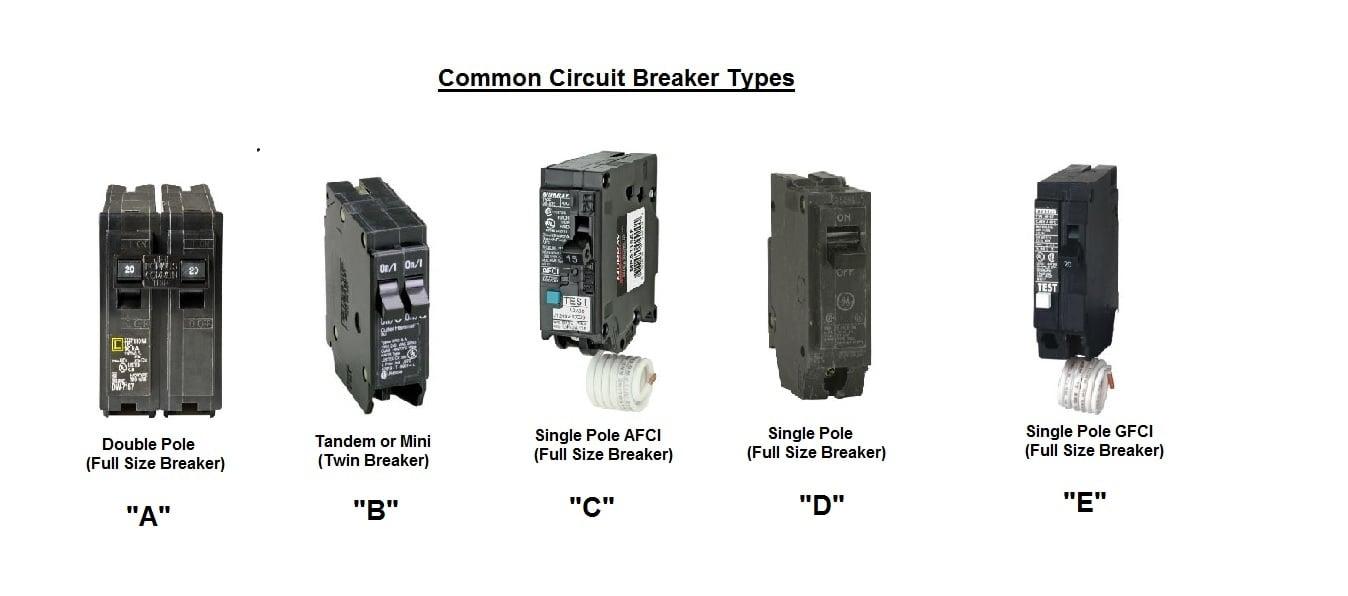
Comparison Table
| Parameter | Bolt-On | Plug-In | Screw-In |
|---|---|---|---|
| Connection Method | Bolted to busbar | Spring clip | Threaded base |
| Contact Stability | Very high | Moderate | Low (aging systems) |
| Installation | Requires torque control | Tool-less | Manual threading |
| Typical Application | Industrial/commercial | Residential | Legacy systems |
| Thermal Performance | Excellent | Adequate | Poor |
Engineering Perspective
The primary difference lies in contact impedance stability over time, which directly affects thermal performance, efficiency, and safety.
4. Types of Bolt-On Circuit Breakers
- Standard Thermal-Magnetic Breakers – General-purpose protection
- High-Amperage Breakers – Used in feeders and large loads
- GFCI Breakers – Protect against ground faults
- AFCI Breakers – Detect arc faults to prevent fires
- Dual-Function Breakers – Combine GFCI and AFCI
- Electronic (Solid-State) Breakers – Provide adjustable and precise protection
- Current-Limiting Breakers – Reduce fault current magnitude rapidly
- Motor Protection Breakers – Designed for high inrush currents
5. Engineering Selection Criteria
5.1 Load Analysis
- Continuous loads should be rated at ≥125%
- Consider:
- Inrush current
- Harmonics from non-linear loads
5.2 Short-Circuit Rating (Interrupting Capacity)
- Must exceed available fault current (kAIC)
- Critical for system safety compliance
5.3 Panel Compatibility
- Always match approved breaker types
- Follow manufacturer and certification requirements
5.4 Environmental Conditions
- Temperature derating
- Humidity and corrosion exposure
- Mechanical vibration (favor bolt-on design)
6. Installation and Torque Considerations
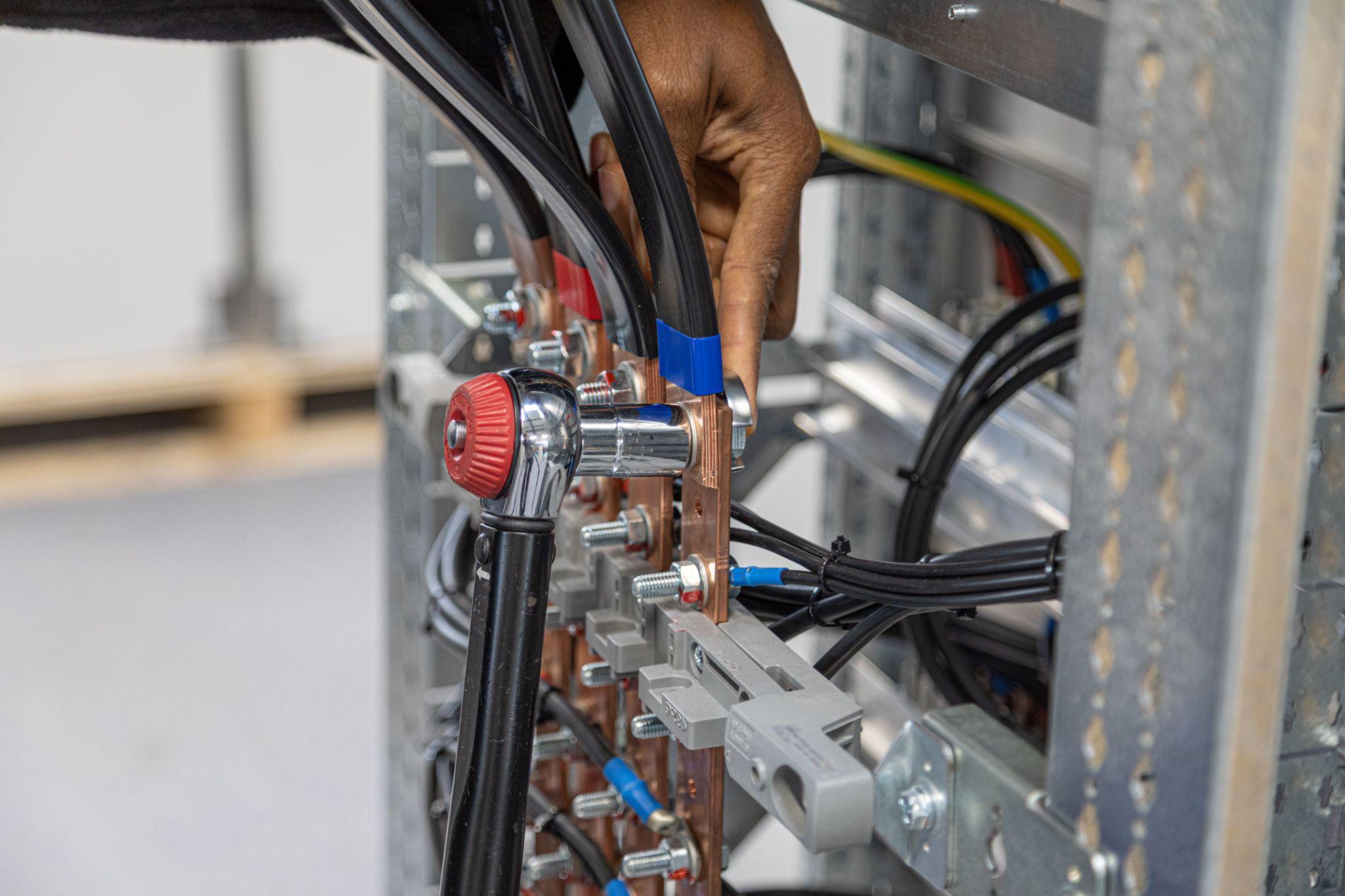
Critical Factor: Torque Control
- Under-tightening → increased resistance, overheating
- Over-tightening → mechanical damage or thread failure
Best Practices
- Use calibrated torque tools
- Follow manufacturer torque specifications
- Recheck connections after thermal cycling
7. Failure Modes and Troubleshooting
7.1 Common Failure Mechanisms
- Loose electrical connections causing heat buildup
- Contact wear increasing resistance
- Arc damage degrading insulation
- Aging components leading to unreliable operation
7.2 Diagnostic Indicators
- Discoloration or burn marks
- Audible buzzing or arcing sounds
- Frequent or unexplained tripping
7.3 Engineering Solutions
- Retighten connections to specified torque
- Replace aged or damaged breakers
- Rebalance or redistribute loads
8. Key Features and Performance Advantages
- High mechanical retention strength
- Stable and low contact resistance
- Reduced risk of arcing and overheating
- Excellent vibration resistance
- Designed for panelboard compatibility
- Supports accessories:
- Auxiliary contacts
- Shunt trip modules
- Remote signaling interfaces
9. FAQ
Q1: Why are bolt-on breakers preferred in industrial systems?
They provide superior mechanical stability and electrical reliability, especially in high-load and vibration-prone environments.
Q2: How critical is torque during installation?
Torque directly impacts contact resistance and thermal performance, making it a key factor in safe operation.
Q3: Can bolt-on breakers replace plug-in breakers?
Only if the panelboard is designed for bolt-on types. Compatibility must always be verified.
Q4: What is the main risk in breaker selection?
Using incompatible or underrated breakers can lead to overheating or failure to trip under fault conditions.
Q5: How often should circuit breakers be inspected?
In industrial applications, inspection is typically performed annually or based on maintenance schedules.
10. Conclusion
Bolt-on circuit breakers provide high reliability, strong mechanical connection, and superior electrical performance compared to other connection types. Their design ensures stable contact with the busbar, reducing thermal losses and improving long-term durability.
For engineering applications, correct selection, torque-controlled installation, and regular maintenance are essential to ensure system safety, efficiency, and operational stability over time.