


Changeover Switch (Transfer Switch): Working Principles, Types, and Engineering Applications
A changeover switch, also known as a transfer switch, is a critical component in power distribution systems used to safely transfer electrical load between multiple power sources such as utility supply and generators. Its design directly impacts system safety, reliability, and continuity of power. This article provides a detailed engineering-level explanation of its working mechanism, types, phase configurations, application scenarios, and selection criteria, helping engineers and system designers implement robust backup power solutions.
Table of Contents
- 1. Fundamentals of Changeover Switches
- 2. Working Principle and Transfer Logic
- 3. Types of Changeover Switches
- 4. Single-Phase vs Three-Phase Systems
- 5. Applications in Power Systems
- 6. Engineering Advantages and Safety Considerations
- 7. Selection Criteria for Engineers
- 8. FAQ
- 9. Conclusion
1. Fundamentals of Changeover Switches
A changeover switch is an electromechanical switching device designed to transfer electrical load between two independent power sources while ensuring mutual exclusivity, meaning only one source supplies power at any given time.
Key Functional Objectives
- Prevent backfeeding into the utility grid
- Ensure safe electrical isolation between sources
- Maintain power continuity during outages
Engineering Context
Improper switching between power sources can result in equipment damage, unstable system operation, or safety hazards for maintenance personnel. Changeover switches mitigate these risks through controlled and predictable switching mechanisms.
2. Working Principle and Transfer Logic
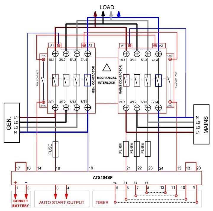
2.1 Transfer Sequence (Automatic System)
-
Normal Condition
Load is connected to the main utility supply -
Power Failure Detection
Voltage or frequency drop is detected -
Generator Start
Backup generator starts and stabilizes -
Load Transfer
Switch disconnects utility and connects generator -
Power Restoration
Utility supply returns and load is transferred back -
Generator Shutdown
2.2 Critical Design Principle
Break-Before-Make (BBM)
- Ensures the first source is disconnected before the second is connected
- Prevents short circuits and backfeeding
2.3 Three-Phase Considerations
- Maintains phase synchronization
- Prevents phase imbalance
- Protects motors and sensitive equipment
3. Types of Changeover Switches
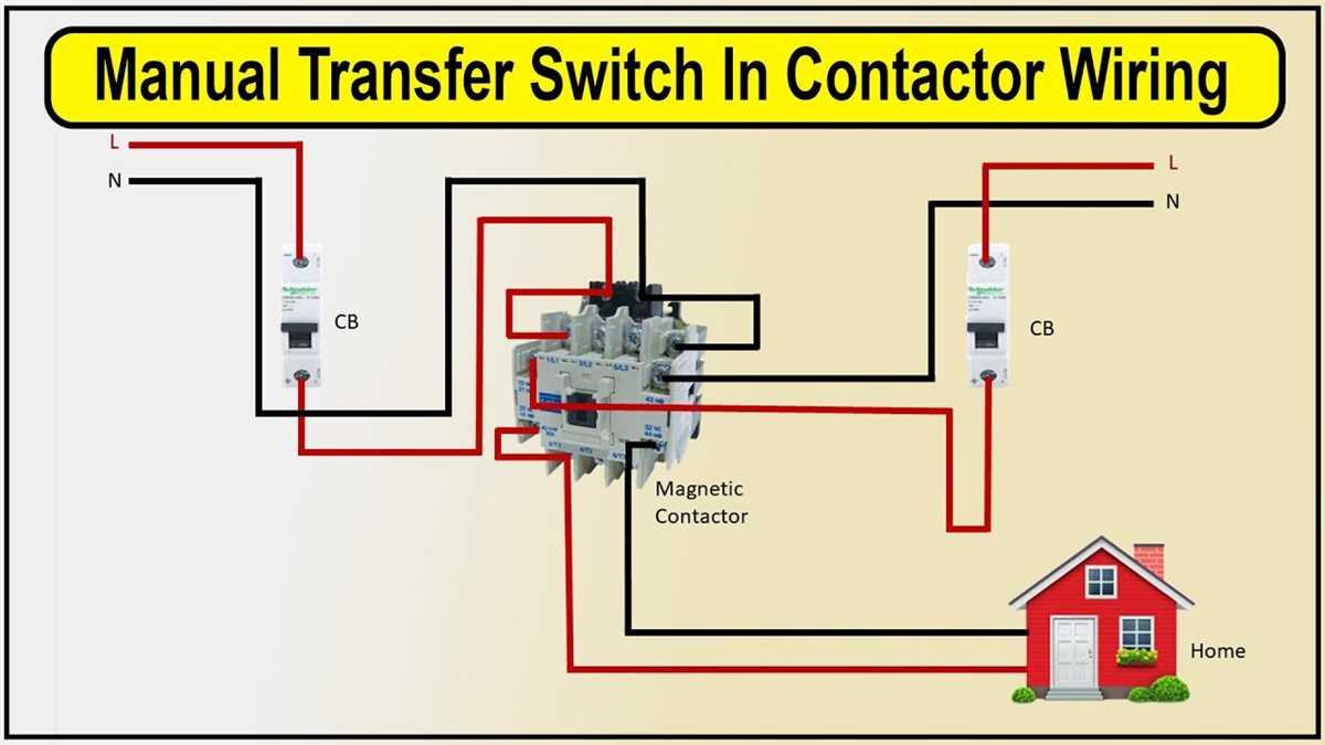
3.1 Manual Changeover Switch
- Requires human operation
- Simple design and low cost
- Suitable for non-critical systems
3.2 Automatic Transfer Switch (ATS)
- Detects power conditions automatically
- Performs rapid switching
- Used in critical applications
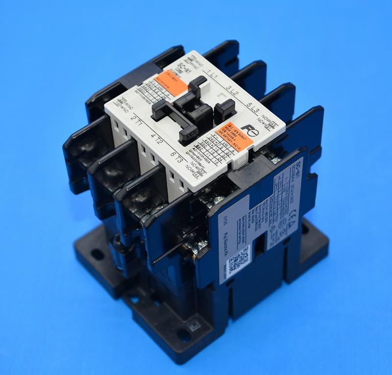
3.3 Motorized Changeover Switch
- Electrically operated mechanism
- Supports remote control or PLC integration
Comparison Table
| Feature | Manual | ATS | Motorized |
|---|---|---|---|
| Operation | Manual | Automatic | Remote/Automatic |
| Response Time | Slow | Fast | Moderate |
| Complexity | Low | High | Medium |
| Cost | Low | High | Medium |
4. Single-Phase vs Three-Phase Systems
Comparison Table
| Parameter | Single-Phase | Three-Phase |
|---|---|---|
| Typical Use | Residential | Industrial |
| Voltage Level | Low | Medium/High |
| Wiring | L, N, Ground | L1, L2, L3, N, Ground |
| Load Type | Lighting, appliances | Motors, HVAC |
| System Complexity | Simple | High |
Engineering Insight
Three-phase systems require phase sequence consistency, proper load balancing, and careful coordination to ensure stable and efficient operation.
5. Applications in Power Systems
5.1 Residential Systems
- Backup power for lighting and essential appliances
5.2 Commercial Systems
- Maintains business continuity
- Prevents operational downtime
5.3 Industrial Systems
- Supports machinery and automation systems
- Enables continuous production
5.4 Healthcare Facilities
- Ensures uninterrupted power for critical equipment
- Requires fast and reliable transfer
5.5 Hybrid Energy Systems
- Enables switching between utility, generator, and solar sources
- Supports energy optimization strategies
6. Engineering Advantages and Safety Considerations
Key Advantages
- Prevents backfeeding and electrical hazards
- Ensures safe isolation between sources
- Reduces downtime during outages
- Improves system reliability
Safety Considerations
- Use interlocking mechanisms to avoid simultaneous connection
- Ensure compliance with applicable standards (IEC, UL)
- Implement proper grounding and neutral handling
7. Selection Criteria for Engineers
7.1 Electrical Rating
- Current rating must meet or exceed load requirements
- Voltage rating must match system specifications
7.2 Switching Type
- Manual for low-criticality applications
- Automatic for high-reliability systems
7.3 Transfer Time
- Critical loads require minimal switching delay
7.4 Mechanical Durability
- Evaluate rated switching cycles
- Consider environmental resistance
7.5 System Compatibility
- Ensure compatibility with generator and panel design
- Confirm installation constraints
8. FAQ
Q1: What is the main purpose of a changeover switch?
To safely transfer electrical load between two power sources while preventing simultaneous connection.
Q2: What is the difference between ATS and manual switches?
ATS operates automatically, while manual switches require user intervention.
Q3: Why is break-before-make important?
It prevents short circuits and backfeeding between power sources.
Q4: Can changeover switches be used with solar systems?
Yes, they are widely used in hybrid energy systems combining grid and renewable sources.
Q5: Which system is better: single-phase or three-phase?
The choice depends on load requirements, with three-phase systems preferred for high-power applications.
9. Conclusion
Changeover switches are essential for ensuring safe, reliable, and continuous power supply in modern electrical systems. Their ability to control source transfer, prevent electrical hazards, and maintain operational stability makes them critical in residential, commercial, and industrial applications.
Careful selection, proper installation, and regular maintenance are key to achieving long-term performance and system reliability.