




Ethernet PHY Selection Guide: How to Choose the Right Physical Layer Transceiver for Your Network Design
Contents
- Quick Overview
- Core Technical Specifications You Must Check
- PHY Family Comparison at a Glance
- Practical Selection Workflow
- Layout and Hardware Implementation Tips
- Common Questions Before Final Selection
- Final Takeaways
Quick Overview
Selecting the right Ethernet PHY is critical for reliable network connectivity in embedded systems, industrial equipment, automotive applications, and IoT devices. The PHY handles the physical layer, converting digital signals from the MAC into analog signals for transmission over copper or fiber. This guide walks through the technical specs, performance trade-offs, and sourcing considerations that matter when picking a PHY for your specific application. We've been through enough PHY-related field failures to know that getting this decision right upfront saves weeks of debugging later.
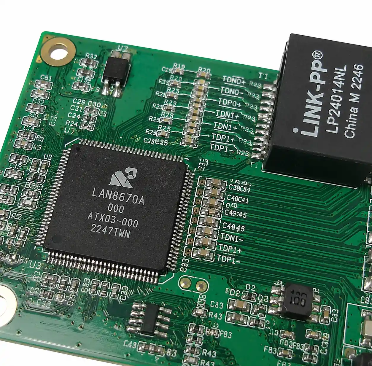 Ethernet PHY transceiver chip on PCB
Core Technical Specifications You Must Check
Understanding Ethernet PHY specs requires familiarity with several critical parameters that directly affect design performance and compatibility.
Data Rate and IEEE Standard Compliance: Ethernet PHYs support 10BASE-T (10 Mbps), 100BASE-TX (100 Mbps), 1000BASE-T (1 Gbps), and multi-gigabit standards like 2.5GBASE-T and 10GBASE-T. Most modern PHYs auto-negotiate multiple speeds. For industrial applications, 10/100 Mbps is often sufficient, while automotive infotainment and ADAS systems increasingly require gigabit or multi-gigabit speeds.
MAC Interfaces (MII, RMII, RGMII, SGMII): MII uses 16 pins for 100 Mbps operation. RMII cuts this to 7-9 pins by using a common reference clock, saving PCB space but requiring more precise clock management. Gigabit applications typically use RGMII with 12 pins and DDR signaling. For board-to-board or longer connections, SGMII uses differential pairs for better noise immunity and fewer traces.
Power Consumption: A typical 100BASE-TX PHY consumes 150-250 mW active, while gigabit PHYs range from 400 mW to over 1W. IEEE 802.3az Energy Efficient Ethernet (EEE) reduces power during low-traffic periods. For battery-powered or thermally constrained designs, carefully evaluate active power, idle power, and wake-up latency.
Latency: PHY latency typically ranges from 200 ns to 800 ns depending on speed and implementation. For time-sensitive networking (TSN) in automotive or industrial automation, deterministic latency and low jitter are critical.
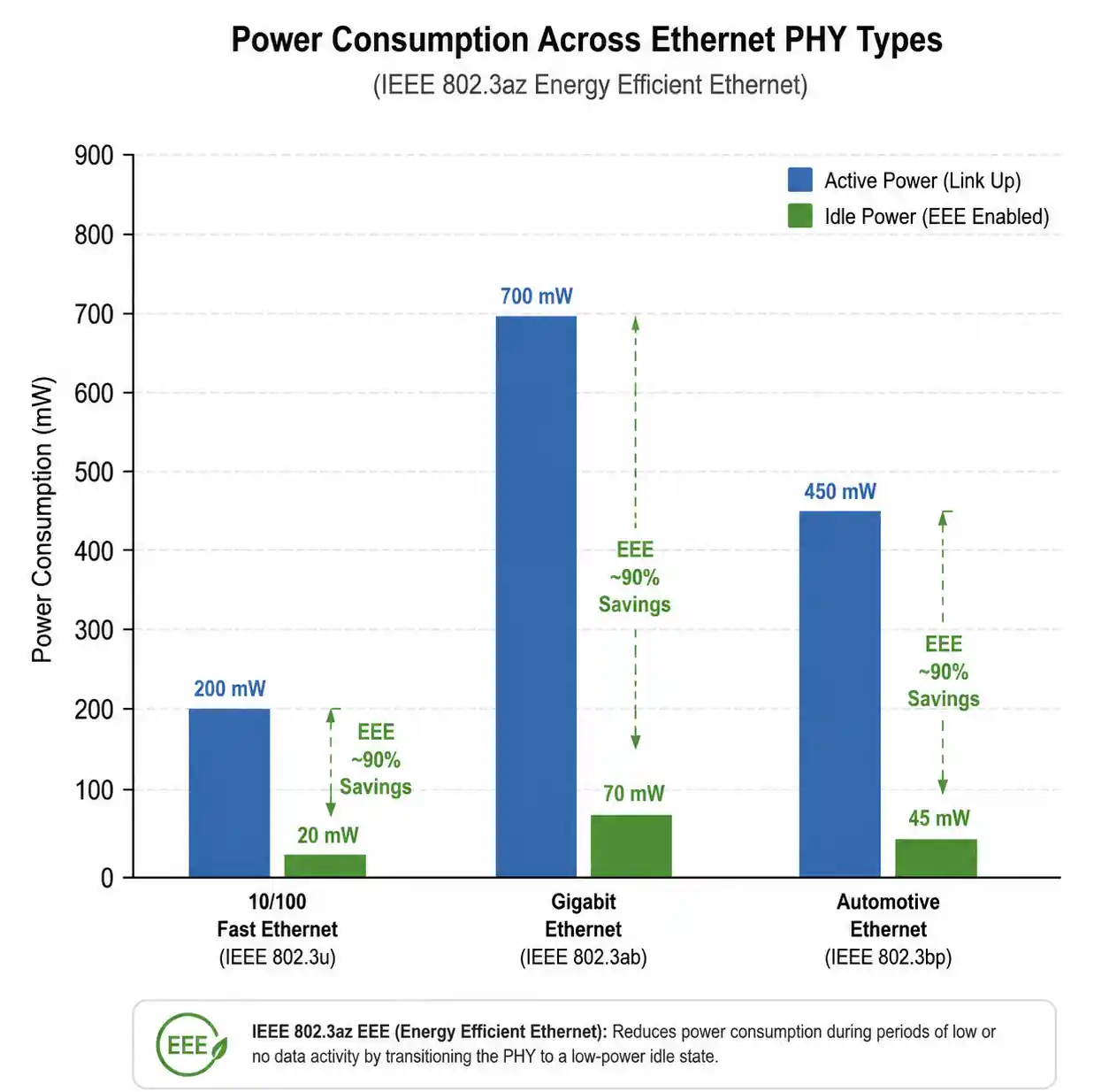 Power consumption comparison chart Ethernet PHY
EMC and ESD Protection: Look for integrated common-mode chokes and ESD protection ratings. IEC 61000-4-2 Level 4 (±8 kV contact, ±15 kV air discharge) is standard for industrial equipment.
Temperature Range: Commercial-grade PHYs run 0°C to +70°C, industrial-grade -40°C to +85°C, and automotive-grade -40°C to +125°C or higher.
PHY Family Comparison at a Glance
Choosing between PHY families requires understanding their technical trade-offs. Here's what we see in the field:
| Parameter | 10/100 Fast Ethernet | Gigabit Ethernet | Automotive Ethernet | Industrial Ethernet |
|---|---|---|---|---|
| Data Rate | 10/100 Mbps | 10/100/1000 Mbps | 100BASE-T1 / 1000BASE-T1 | 10/100 Mbps w/ determinism |
| Typical Power | 150-250 mW | 500-900 mW | 300-600 mW | 200-400 mW |
| MAC Interface | MII / RMII | RGMII / SGMII | RGMII / MII | MII / RMII / SPI |
| Pin Count | 32-48 pin QFN | 48-64 pin QFN | 32-48 pin QFP | 32-56 pin QFN |
| Cable Type | Cat5 UTP, 100m | Cat5e/Cat6, 100m | Single pair, 15m | Cat5 STP, 100m |
| Temp Range | 0°C to +70°C | -40°C to +85°C | -40°C to +125°C | -40°C to +85°C |
| ESD Protection | ±2 kV contact | ±4 kV contact | ±8 kV contact | ±6 kV contact |
| Typical Applications | IoT, basic networking | Enterprise switches, NAS | In-vehicle networks, ADAS | Factory automation, PLCs |
| Unit Cost (10k) | $0.80-$1.50 | $2.50-$5.00 | $3.50-$8.00 | $2.00-$4.50 |
Application-Specific Selection Matrix
| Application | Recommended PHY Type | Key Selection Criteria |
|---|---|---|
| IoT sensor node (battery) | 10/100 Fast Ethernet w/ EEE | Lowest power, wake-on-LAN |
| Industrial PLC | Industrial Fast Ethernet | Extended temp, cable diagnostics, TSN |
| Automotive gateway | Gigabit Automotive Ethernet | AEC-Q100 Grade 2/3, IEEE 1588 |
| Home router / AP | Gigabit Ethernet | Cost-optimized, QoS features |
| Medical monitoring | 10/100 Fast Ethernet | IEC 60601, low EMI, isolated |
Practical Selection Workflow
Here's the systematic approach we use on actual projects:
Step 1: Define data rate and cable length. Industrial sensors and simple controllers work fine with 10/100 Mbps – lower cost and power. Video streaming, automotive backbones, and data acquisition need gigabit. Standard 100BASE-TX supports 100 meters, but automotive PHYs are optimized for short 15-meter runs with reduced EMI filtering.
Step 2: Match the MAC interface. If your MCU only has RMII, selecting an RGMII-only PHY creates unnecessary complexity. For gigabit designs, verify whether your MAC supports RGMII delay modes – mismatch causes intermittent link failures.
Step 3: Evaluate power and thermal constraints. Calculate total dissipation including PHY active power, magnetics losses, and termination resistor heating. For designs without active cooling, check θJA and ensure die temperature stays within limits. Account for inrush current during power-up.
Step 4: Check compliance requirements. Automotive needs AEC-Q100. Industrial systems need IEC 61000 EMC compliance and potentially ATEX. Medical devices require IEC 60601-1. "Design-in" support without certified test reports creates risk during system certification.
Step 5: Consider diagnostics and management. Advanced PHYs include cable diagnostics (TDR for open/short detection), link quality monitoring, and IEEE 1588 PTP hardware timestamping. These add cost but significantly reduce field service time.
Step 6: Assess vendor ecosystem. Check for Linux PHY drivers (mainline or vendor-provided), reference designs, and application notes. Vendors with strong FAE support and detailed layout guidelines reduce development risk.
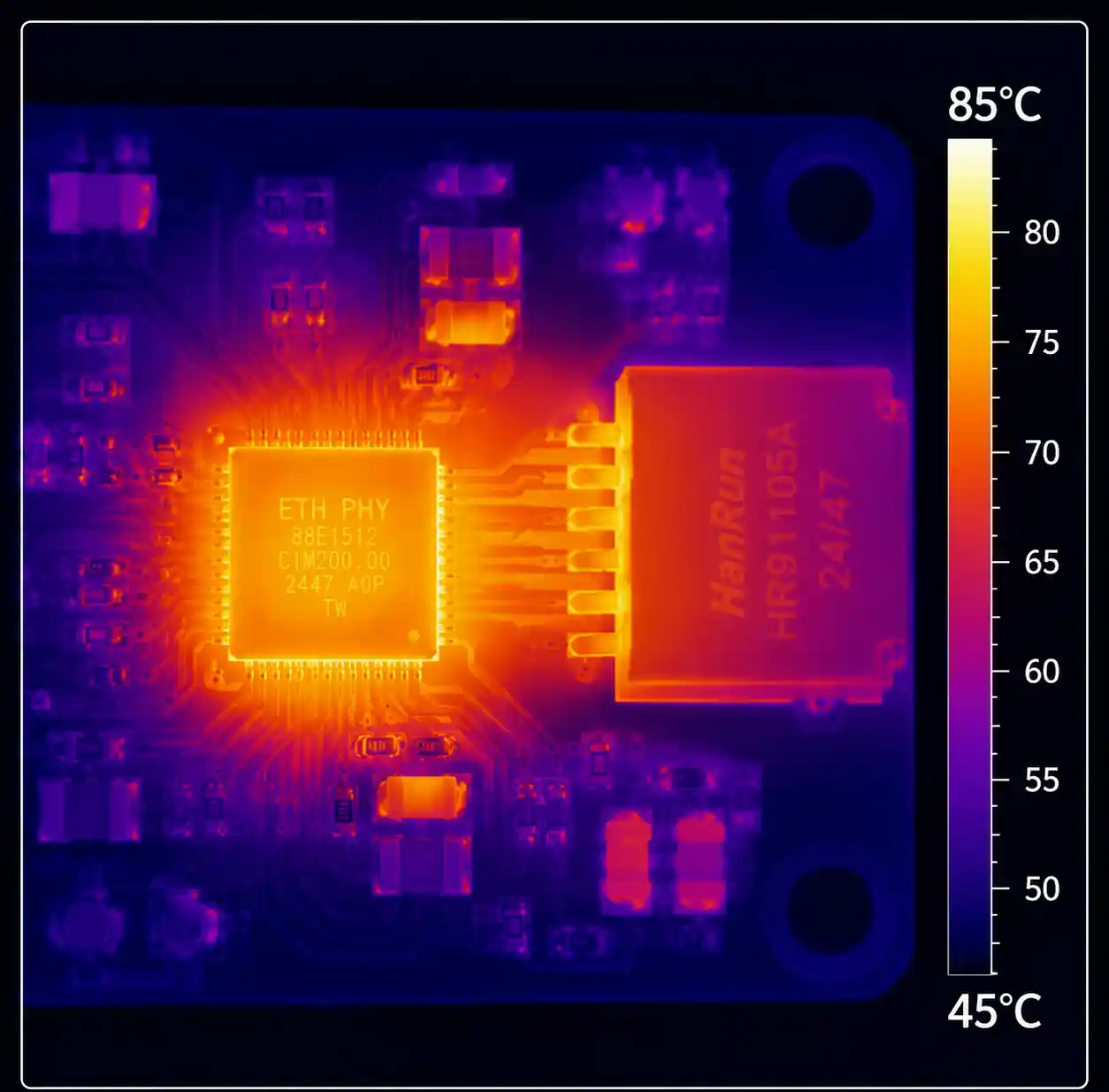 Thermal image showing PHY heat dissipation
Layout and Hardware Implementation Tips
PCB Layout and Impedance Control: MDI differential pairs must maintain 100Ω ±10% differential impedance – typically 6-8 mil traces with 6-8 mil spacing on standard FR-4. Avoid routing across ground plane splits or near high-speed clocks.
Magnetics Selection and Placement: Place magnetics as close to the RJ45 connector as possible – long traces between PHY and magnetics degrade signal quality and increase EMI. Integrated magnetics simplify design; discrete allow custom turns ratios for automotive reduced-voltage applications.
Crystal vs. External Clock: Crystals offer better jitter performance (<50 ps RMS) but occupy more board space. External clocks are cheaper but may introduce jitter. For multi-PHY designs, a single low-jitter oscillator can clock multiple PHYs.
Power Sequencing: Many PHYs require specific power-up sequences between core, I/O, and analog supplies. Violating these can cause latch-up. Use power sequencing circuits or software-controlled regulators.
Common Design Errors:
| Mistake | Symptom | Solution |
|---|---|---|
| Missing RGMII clock delay | Intermittent link-up, packet loss | Configure internal delays via strapping/registers |
| Inadequate ground plane under MDI | EMC failures, instability at long cables | Maintain continuous ground plane |
| Wrong magnetics turns ratio | No link or short cable length support | Verify line voltage and match magnetics |
| Shared supply with noisy digital | Increased BER, link drops | Separate analog/digital supplies with ferrite beads |
| No ESD protection on connector | Field failures after hot-plug events | Add TVS diodes on RJ45 pins |
Signal Integrity Validation: Measure eye diagrams at the connector before production. Pay attention to differential pair skew (<25 ps), rise/fall time symmetry, and overshoot/undershoot. Use a network analyzer to verify return loss if designing custom magnetics or long PCB traces.
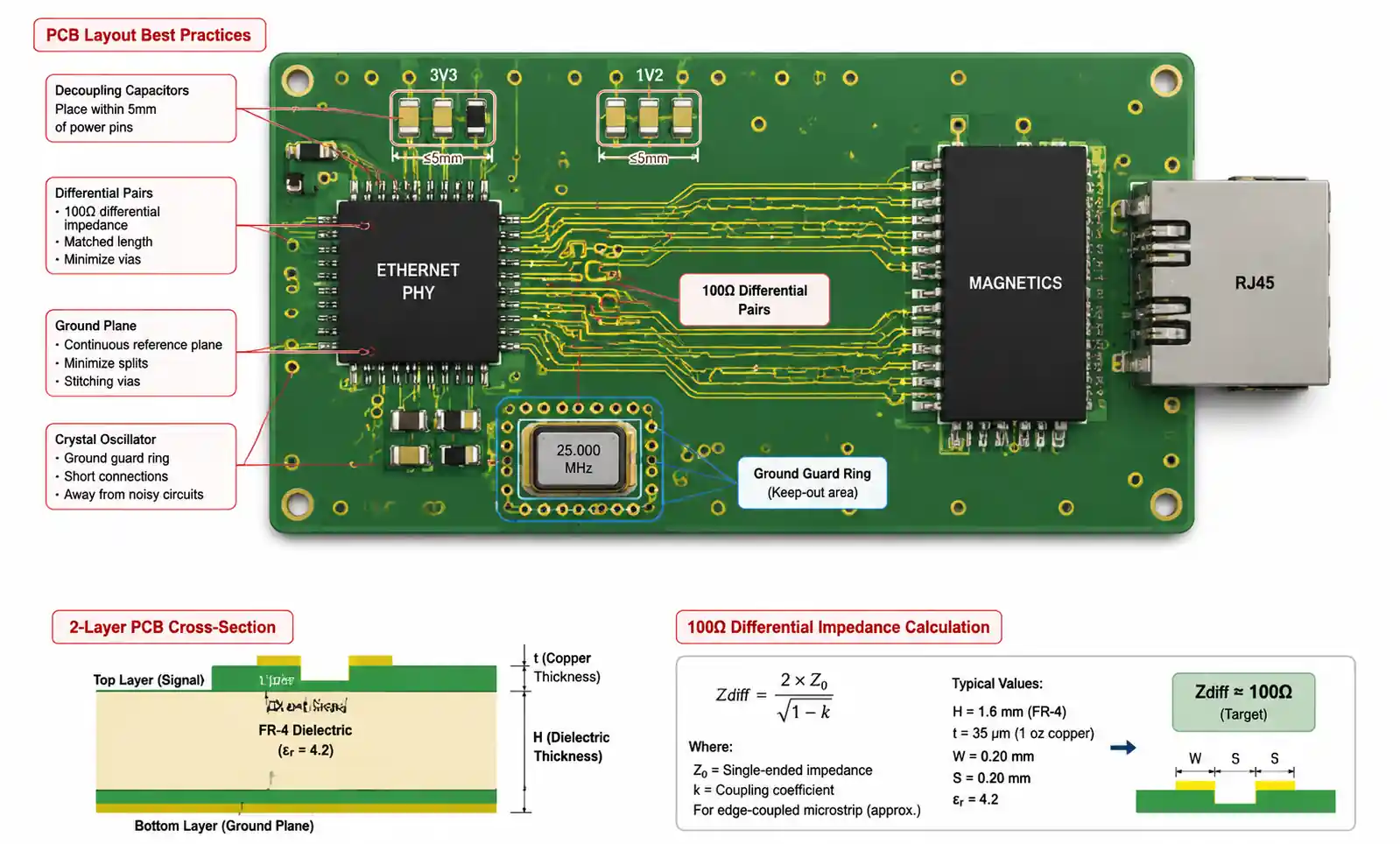 Proper PCB layout Ethernet PHY differential pairs
Common Questions Before Final Selection
What's the difference between MII, RMII, and RGMII?
MII uses 16 pins with separate TX/RX clock domains for 10/100 Mbps. RMII reduces pin count to 7-9 with a shared reference clock – saves PCB space but needs more careful clock routing. RGMII supports gigabit speeds with 12 pins using DDR signaling. Choose based on your MAC interface availability and PCB space constraints.
Can I use the same PHY for industrial and commercial applications?
You can if your enclosure maintains the temperature range, but you may fail EMC certification due to insufficient ESD and surge protection. Industrial-grade PHYs include enhanced ESD structures and ruggedized packages. If you need CE marking or IEC 61000 compliance, starting with industrial-grade significantly reduces certification risk.
How do I calculate decoupling capacitor values?
Follow the datasheet recommendations exactly – manufacturers specify values based on extensive testing of their chip's specific supply impedance. Typical configuration: 10 µF bulk + 1 µF mid-range + 100 nF X7R high-frequency close to each supply pin. If you see link instability, measure supply rail noise with an oscilloscope and add capacitance where ripple exceeds 50 mV peak-to-peak.
What does Energy Efficient Ethernet (EEE) do and should I enable it?
EEE allows the PHY to enter Low Power Idle during no traffic, reducing power 30-60% in typical usage. Both link partners must support it. However, EEE adds wake-up latency (16-40 µs) that can impact VoIP or industrial control. Enable it for battery-powered IoT; disable it for real-time control systems.
How do I troubleshoot intermittent link failures?
Start with physical layer: measure cable impedance (should be 100Ω ±15Ω), test for opens/shorts using PHY diagnostics or a cable tester, verify connector crimping. Read PHY registers for link status, auto-negotiation results, and error counters. Common software issues: incorrect RGMII clock delay settings (try swapping between MAC-delayed and PHY-delayed modes), improper MDIO initialization, or MAC buffer overflow.
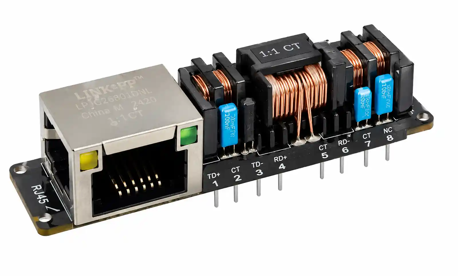 Ethernet magnetics transformer isolation module
Final Takeaways
Selecting the right Ethernet PHY comes down to balancing data rate, interface compatibility, power budget, and environmental requirements. For most industrial and commercial applications, prioritize an established vendor with proven reference designs for your MAC controller and confirmed long-term production commitment. Fast Ethernet (10/100) remains the cost-effective choice for lower-bandwidth applications; gigabit is essential for video, data acquisition, and high-throughput systems. If your application needs real-time determinism, focus on PHYs with IEEE 1588 PTP support and low, consistent latency. For harsh environments, verify temperature rating, ESD protection, and EMC compliance match your certification requirements. Get your PHY selection right early, and you'll avoid costly hardware respins and field failures down the road.
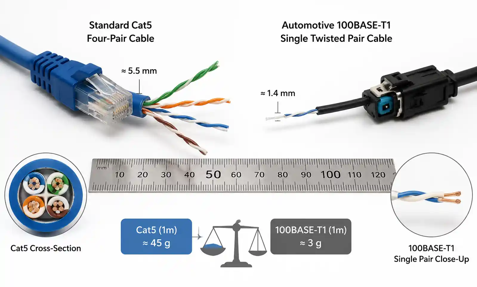 Automotive Ethernet single-pair cable harness
