




USB Power Delivery: Selection and Implementation Guide for Engineers
Table of Contents
- Introduction
- Key Technical Parameters Explained
- How to Choose the Right USB PD Solution
- Performance Comparison by Power Level
- Design Considerations and Common Pitfalls
- Supply Chain and Sourcing Considerations
- FAQ
- Conclusion
1. Introduction
USB Power Delivery (USB PD) has transformed power delivery in consumer electronics, industrial equipment, and automotive applications. This universal charging protocol enables intelligent power negotiation up to 240W over a single USB Type-C cable, eliminating multiple proprietary chargers. For design engineers and procurement teams, understanding USB PD specifications, controller selection, and implementation requirements is essential for product success.
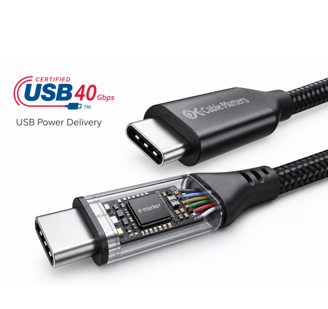 USB Type-C connector with USB PD cable showing e-marker chip
This guide provides actionable technical insights for selecting and implementing USB PD. Whether you're developing a fast-charging mobile device, USB-powered industrial sensor, or laptop power system, this resource covers power profiles, voltage negotiation protocols, component selection, and common design pitfalls that delay certification or compromise performance. The USB PD 3.1 specification supports Extended Power Range (EPR) up to 240W at 48V, expanding applications into monitor power delivery, docking stations, portable power tools, and industrial equipment.
2. Key Technical Parameters Explained
Understanding USB PD technical parameters is essential for proper component selection and system design. The protocol operates through Configuration Channel (CC), which handles power negotiation between source and sink devices.
Power Delivery Profiles and Voltage Levels
USB PD 3.1 defines Standard Power Range (SPR) and Extended Power Range (EPR). SPR covers 5V, 9V, 15V, and 20V at up to 5A (100W maximum). EPR adds 28V, 36V, and 48V levels, extending maximum power to 240W. Each voltage level supports multiple current options through Power Data Objects (PDOs), which the source advertises during initial negotiation.
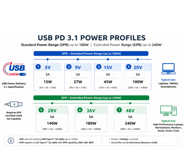
USB PD power profiles chart showing SPR and EPR voltage levels
Configuration Channel (CC) Pin Functionality
CC pins serve multiple critical functions: cable orientation detection, current capability advertisement through Rp/Rd resistor values, and USB PD communication via Biphase Mark Coding (BMC) at 300 kHz. For Dual-Role Power designs, CC pins must support dynamic role swapping. Incorrect CC pin termination is among the most common USB PD certification failures. Source devices use pull-up resistors (Rp) from 10kΩ to 80kΩ to indicate 1.5A or 3A capability. Sink devices use 5.1kΩ pull-down resistors (Rd).
| Parameter | SPR Range | EPR Range | Typical Application | Key Consideration |
|---|---|---|---|---|
| Voltage | 5V - 20V | 28V - 48V | Laptop charging, monitors | Higher voltage reduces cable losses |
| Current | Up to 5A | Up to 5A | Variable by PDO | Requires e-marked cable >3A |
| Maximum Power | 100W | 240W | Desktop laptops, displays | Thermal management critical |
| Communication | 300 kHz BMC | 300 kHz BMC | All implementations | Clean signal integrity required |
| Response Time | <190µs | <190µs | Protocol timing | Firmware optimization essential |
When designing for EPR levels above 100W, cable qualification becomes mandatory. EPR cables must contain identification chips, and connector ratings must match—standard USB Type-C connectors rated for 5A require derating for sustained 48V/5A operation.
3. How to Choose the Right USB PD Solution
Selecting appropriate USB PD components depends on implementing source (charger), sink (device), or dual-role functionality. The decision framework should prioritize power requirements, certification timeline, firmware flexibility, and supply chain robustness.
USB PD Controller Selection
For designs requiring maximum flexibility and custom protocol handling, standalone USB PD controllers offer dedicated hardware for protocol management with integrated analog front-end for CC communication, power path control, and I²C/SPI interfaces. Examples include Cypress CYPD3177 and Texas Instruments TPS65987D. Standalone controllers excel in high-power applications above 65W where precise voltage transition control and custom Vendor Defined Messages are required.
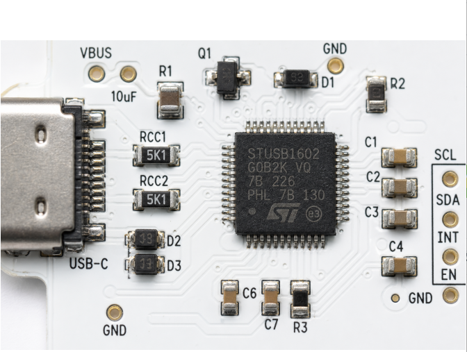
USB PD power profiles chart showing SPR and EPR voltage levels
Integrated solutions combining USB PD controller with DC-DC conversion (like Infineon EZ-PD CCG7D) reduce BOM cost and PCB area but sacrifice protocol customization. For power banks, chargers, and adapters with straightforward firmware, integrated solutions accelerate time-to-market using pre-qualified reference designs.
| Power Level | Controller Type | Efficiency | BOM Cost | Best Application |
|---|---|---|---|---|
| <18W (5V-9V) | Integrated PD+Buck | 85-88% | $1.50-2.50 | Phone chargers, adapters |
| 18-65W | Standalone + Buck | 90-93% | $3.00-5.00 | Laptop chargers, hubs |
| 65-100W | Standalone + High-current | 91-94% | $5.00-8.00 | High-power laptop charging |
| 100-240W (EPR) | Standalone + GaN FETs | 93-96% | $12.00-20.00 | Desktop replacement, displays |
Designs exceeding 60W (3A at 20V) require electronically marked cables (e-marker chips). Your product must correctly read e-marker data during cable discovery to limit power appropriately. Never assume cable capability—always query the e-marker and default to 5V/3A maximum if no marker is detected.
4. Performance Comparison by Power Level
Different power levels present distinct engineering tradeoffs in efficiency, thermal management, and cost. Understanding these tradeoffs guides appropriate specification selection.
Efficiency Across Power Levels
Conversion efficiency directly impacts thermal design. A 100W adapter at 90% efficiency dissipates 10W as heat, requiring heatsinking or active cooling. Moving to 93% efficiency (achievable with GaN FETs) reduces dissipation to 7W—a 30% thermal improvement. For battery-powered devices, higher efficiency extends runtime.
Thermal Performance by Implementation
Standard silicon MOSFETs in synchronous buck topology at 65W typically require 5-8 cm² copper area per watt dissipated, or forced airflow in enclosed designs. Gallium Nitride (GaN) FETs reduce switching losses by 40-60%, enabling passive cooling in many 100W+ designs. However, GaN components cost 2-3× more than silicon equivalents.
| Topology | Power Range | Efficiency | Thermal | Cost | Use Case |
|---|---|---|---|---|---|
| Integrated Buck | <30W | 85-88% | Good | 1.0× | Phone chargers |
| Discrete Si Buck | 30-65W | 90-92% | Moderate | 1.3× | Laptop chargers |
| Discrete GaN | 65-140W | 92-95% | Excellent | 2.2× | High-power laptops |
| Multi-phase GaN | 140-240W | 93-96% | Careful design needed | 3.5× | EPR displays |
When evaluating controller and power stage combinations, obtain efficiency curves at your target output voltage and load current. Real-world efficiency at 50-75% load and worst-case input voltage often drops 2-4 percentage points below datasheet peak values.
5. Design Considerations and Common Pitfalls
USB PD implementation presents specific design challenges that can delay certification or cause field failures if not properly addressed.
CC Pin Circuit Design Errors
The most frequent certification failure involves incorrect CC pin termination. Source devices must implement dual Rp resistors (one per CC pin) with precise tolerance—typically ±5%. Resistor values directly communicate current capability: 10kΩ indicates 3A capability, while 22kΩ indicates 1.5A. Using incorrect values causes negotiation failures or overcurrent conditions. CC pins require ESD protection rated for ±8kV contact discharge per IEC 61000-4-2. Standard TVS diodes often have excessive capacitance (>50pF), distorting BMC communication signals. Use specialized low-capacitance TVS devices under 15pF.
VBUS Voltage Transition Timing
During voltage negotiation, VBUS must transition between voltage levels within specified timing windows. The specification allows 275ms (SPR) or 750ms (EPR) for voltage transition after Accept message. However, the transition must be monotonic—voltage cannot overshoot or undershoot by more than ±5%. This requires careful output capacitor selection and soft-start implementation. For 100W designs, 100-220µF ceramic capacitance (after derating) plus 200-470µF electrolytic is typical.
EMI and Signal Integrity
High-frequency switching in DC-DC converters generates EMI that can couple into CC communication lines. Proper PCB layout segregates power stage switching nodes from CC traces. Maintain at least 8mm separation between high-current switching paths and CC routing. For multi-layer boards, route CC as differential pairs on an inner layer with solid ground reference.
| Common Pitfall | Symptom | Root Cause | Prevention |
|---|---|---|---|
| Negotiation failure >3A | Device charges at 15W max | Incorrect Rp resistors | Verify 10kΩ ±5% resistors |
| Intermittent disconnects | Random interruptions | High-capacitance ESD | Use <15pF TVS diodes |
| Voltage overshoot | Device resets on transition | Insufficient capacitance | Add bulk caps, soft-start |
| Failed EMC testing | Emissions exceed limits | Poor PCB layout | Follow layout guidelines |
| Thermal shutdown | Overheats under load | Inadequate thermal design | Thermal simulation required |
6. Supply Chain and Sourcing Considerations
USB PD controller availability and lead times significantly impact product launch schedules. The controller market is concentrated among few key suppliers, making second-source strategies essential.
Vendor Ecosystem and Availability
Major USB PD controller vendors include Cypress (Infineon), Texas Instruments, ON Semiconductor, STMicroelectronics, and Weltrend. Cypress EZ-PD controllers dominate laptop and high-power applications with extensive firmware examples. TI offers highly integrated solutions for adapters and chargers. ON Semi focuses on cost-optimized mid-power solutions. During recent semiconductor shortages, USB PD controllers experienced 26-52 week lead times.
For high-volume production above 100K units annually, engage directly with manufacturer FAEs to secure allocation. For lower volumes, authorized distributors (Digi-Key, Mouser, Arrow) provide smaller quantities at 15-30% price premiums.
Certification and Compliance Timeline
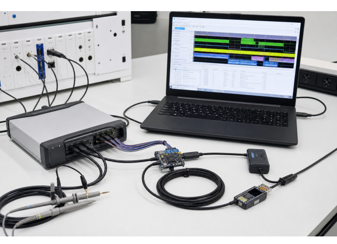
USB-IF certification requires compliance testing at authorized labs. The process involves Interoperability Testing (2-3 weeks) and Protocol Layer Testing (1-2 weeks). Budget $8,000-$15,000 for full certification depending on device complexity. Pre-compliance testing using protocol analyzers (Ellisys, Total Phase) helps identify issues early. Factor 3-6 months total time from design freeze to certified products including regulatory testing.
| Vendor | Key Products | Lead Time | Best For | Second Source |
|---|---|---|---|---|
| Infineon (Cypress) | EZ-PD CCG series | 16-26 weeks | Laptop, high-power | Limited |
| Texas Instruments | TPS65987/988 | 18-24 weeks | Adapter, industrial | Moderate |
| ON Semiconductor | FUSB302/307/312 | 12-20 weeks | Cost-sensitive | Good alternatives |
| STMicroelectronics | STUSB4500/4710 | 14-22 weeks | Mid-power | Limited |
| Weltrend | WT6632/WT6636 | 8-16 weeks | Budget chargers | Good alternatives |
FAQ
What is the difference between USB PD 3.0 and USB PD 3.1?
USB PD 3.1 adds Extended Power Range (EPR) support, enabling power delivery up to 240W at voltages up to 48V. USB PD 3.0 is limited to 100W at 20V maximum. PD 3.1 also introduces Adjustable Voltage Supply (AVS) for fine-grained voltage control. For designs requiring over 100W, PD 3.1 compliant controllers are mandatory.
How do I calculate the required bulk capacitance for VBUS?
Use C = (I × t) / ΔV, where I is load current, t is transition time (typically 10-50ms), and ΔV is acceptable voltage droop (typically 5% of VBUS). For a 100W system at 20V (5A), targeting 5% droop over 20ms: C = (5A × 0.02s) / 1V = 100mF. Account for capacitor derating (ceramic lose 50-80% capacitance at rated voltage), requiring 200-400µF ceramic rated capacitance.
Can I use USB PD in automotive applications?
Yes, but automotive environments require additional considerations. Controllers must meet AEC-Q100 qualification with appropriate temperature grades (typically Grade 2: -40°C to 105°C minimum). Automotive voltage transients (ISO 7637-2) exceed standard USB specifications, requiring enhanced input protection. EMC requirements (CISPR 25) are more stringent. Expect 15-25% cost premium for automotive-grade components.
What are key parameters to check in a USB PD controller datasheet?
Critical specifications include maximum supported power level (SPR or EPR), number of VBUS power paths supported, integrated gate drivers, I²C/SPI interface speed, firmware customization capability, response time specifications, ESD protection levels on CC pins, operating temperature range, and package thermal resistance. Verify availability of reference designs and certification support.
How to handle long lead times for USB PD controllers?
Design with controllers offering multiple package options to increase availability, establish relationships with multiple authorized distributors, consider functionally-equivalent alternatives during design phase, maintain 3-6 month inventory buffer for production, and engage with vendor FAEs early to secure allocation for volume production.
8. Conclusion
Successful USB PD implementation requires balancing power requirements, efficiency targets, thermal constraints, certification timelines, and supply chain realities. For applications under 65W, integrated solutions with pre-certified reference designs accelerate development. For 65-100W SPR designs, discrete controllers with GaN power stages optimize efficiency. EPR implementations above 100W demand careful attention to cable qualification and thermal management.
Before finalizing your design, verify these critical items: CC pin termination matches current capability specification exactly, VBUS bulk capacitance handles worst-case load transients with under 5% droop, thermal design maintains junction temperatures below absolute maximum under sustained load, and selected controllers have reasonable lead times or committed allocation.
