MEMS Sensor Selection Guide: Practical Considerations for Design Engineers
When you're knee-deep in a new product design and need to add motion sensing, environmental monitoring, or precision measurement capabilities, MEMS sensors often become the go-to solution. But with hundreds of MEMS devices on the market—each claiming superior performance—how do you actually choose the right one for your application?
This guide walks through the practical considerations that matter when selecting MEMS sensors for real-world designs. We'll cover the key parameters that impact system performance, discuss trade-offs you'll face during component selection, and highlight common integration mistakes that can derail your design schedule.
Table of Contents
- What MEMS Technology Brings to Modern Electronics
- Key MEMS Sensor Types and Operating Principles
- Critical Selection Parameters You Can't Ignore
- Application-Specific Selection Criteria
- PCB Layout and Integration Considerations
- Common Design Pitfalls and How to Avoid Them
- FAQ
- Conclusion
1. What MEMS Technology Brings to Modern Electronics
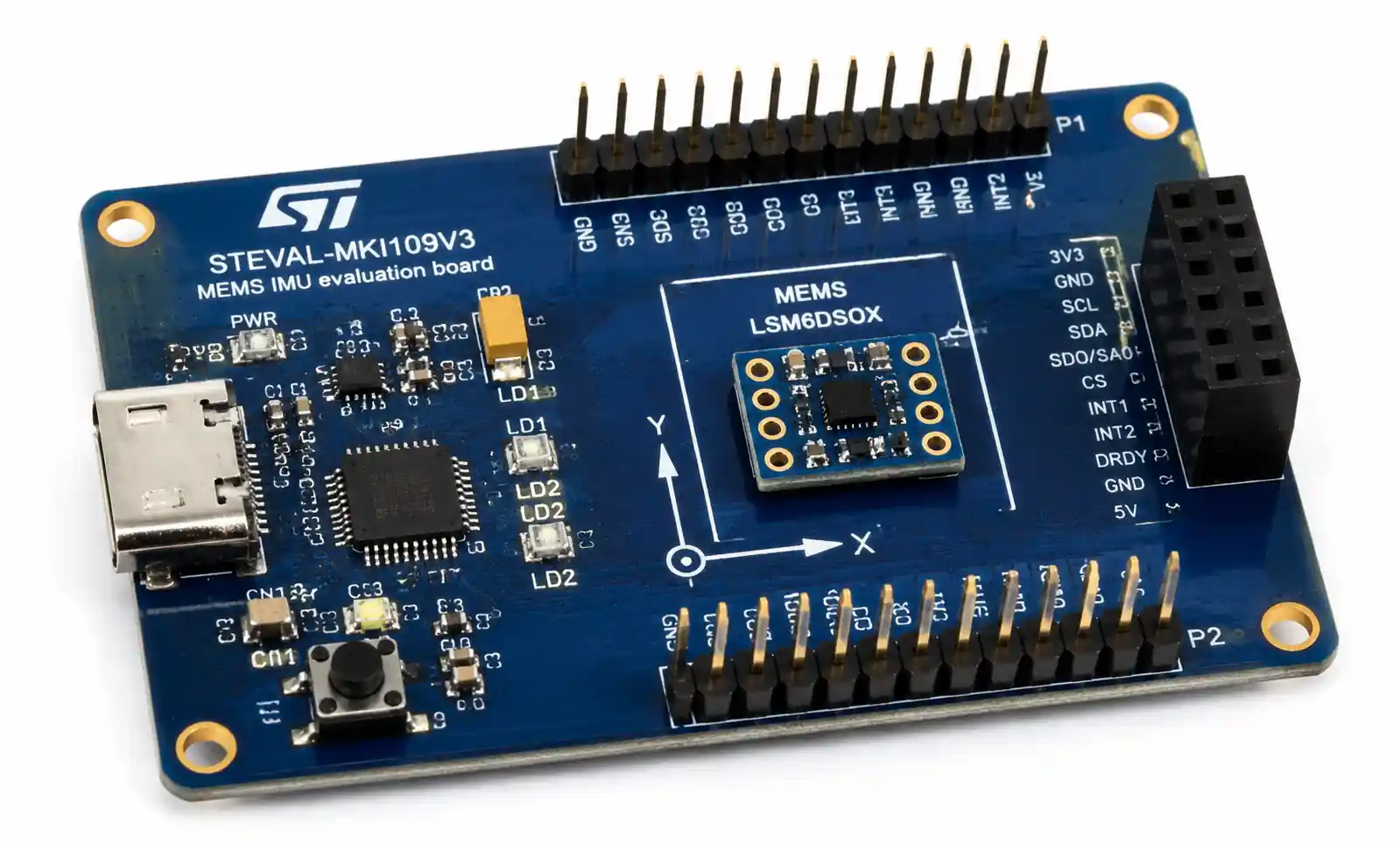
MEMS—Micro-Electro-Mechanical Systems—integrate mechanical elements, sensors, actuators, and electronics on a single silicon substrate. The technology has matured significantly over the past two decades, and MEMS sensors now handle tasks that previously required bulky, power-hungry discrete components.
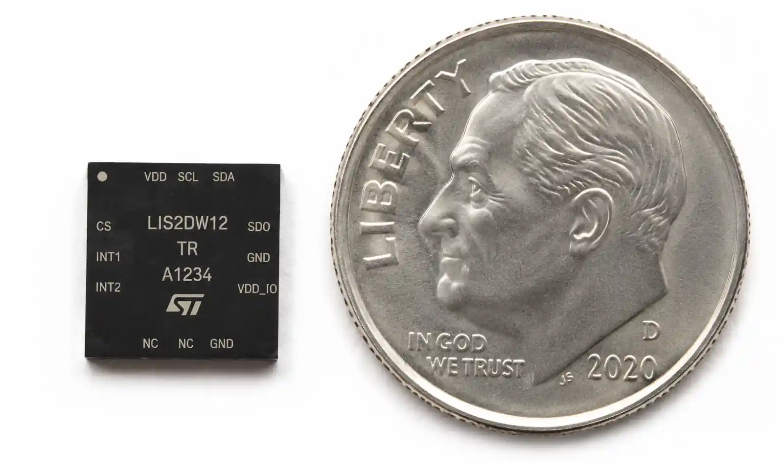
The key advantage of MEMS is the combination of small form factor, low power consumption, and batch manufacturing scalability. A MEMS accelerometer in a 3x3mm LGA package can deliver performance that would have required a sensor ten times larger just fifteen years ago. This size reduction matters not just for consumer wearables—it's equally critical in space-constrained industrial controllers and automotive safety systems.
However, MEMS devices are not without trade-offs. The mechanical structures inside these sensors are susceptible to environmental stress, thermal effects, and long-term drift. Understanding these limitations upfront will save you from costly redesigns later.
2. Key MEMS Sensor Types and Operating Principles
Different MEMS sensor types use distinct physical principles to measure their target parameters. Knowing how a sensor works helps you understand its strengths and weaknesses.
Accelerometers measure linear acceleration using proof masses suspended by flexible beams. When acceleration occurs, the proof mass displaces, and capacitive, piezoresistive, or piezoelectric sensing elements detect this movement. Capacitive sensing dominates consumer and industrial MEMS accelerometers due to its low power consumption and good noise performance.
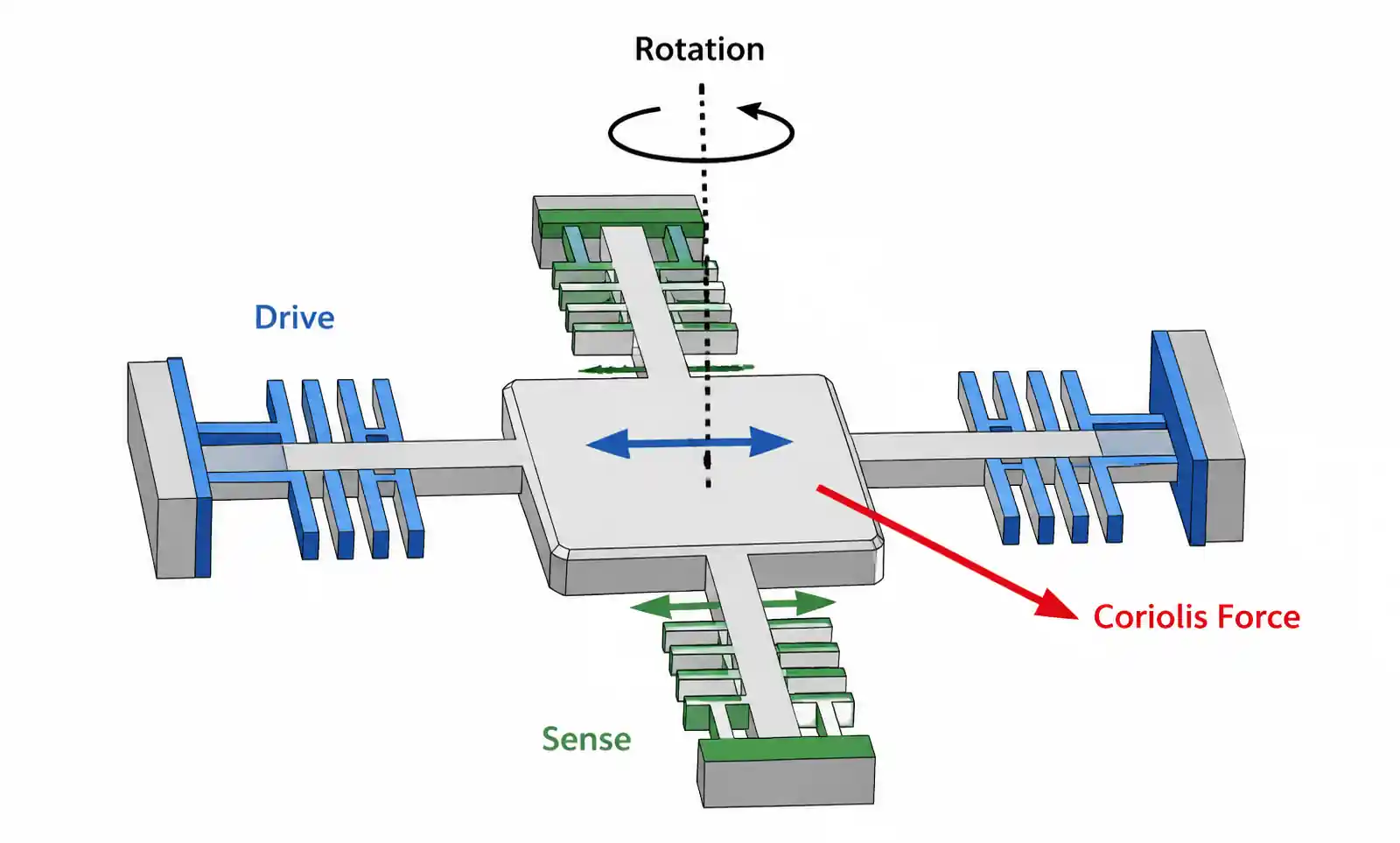
Gyroscopes measure angular velocity through the Coriolis effect. A vibrating proof mass experiences a Coriolis force when the sensor rotates, causing displacement perpendicular to both the vibration direction and rotation axis. This displacement is measured capacitively. MEMS gyros are more complex than accelerometers and typically consume more power.
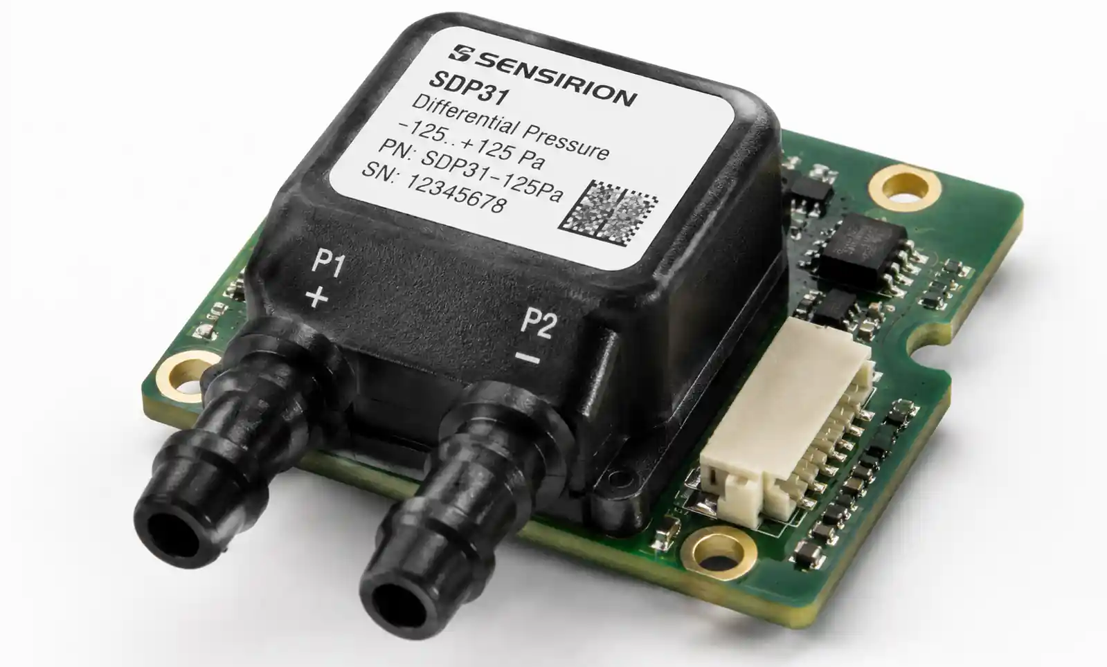
Pressure sensors use a flexible diaphragm that deflects under applied pressure. Piezoresistive elements on the diaphragm change resistance with mechanical stress, allowing pressure measurement. MEMS pressure sensors range from absolute pressure devices for barometric measurement to differential pressure sensors for flow monitoring.
Microphones convert sound pressure into electrical signals using a flexible membrane and a fixed backplate, forming a capacitor. Sound waves cause membrane deflection, changing capacitance. MEMS microphones have largely replaced electret condenser microphones in smartphones and IoT devices due to their superior reliability and automated assembly compatibility.
Environmental sensors measure temperature, humidity, and gas concentration. MEMS temperature sensors often use thermal diodes or resistors. Humidity sensors rely on capacitive or resistive sensing with moisture-sensitive dielectric materials. Gas sensors use heated metal oxide films whose resistance changes upon gas exposure.
3. Critical Selection Parameters You Can't Ignore
When evaluating MEMS sensors, several parameters directly impact whether your design will meet performance requirements.
Measurement Range and Resolution
The measurement range must cover your application's operating conditions with margin. An accelerometer for vehicle crash detection needs ±50g or higher range, while a wearable fitness tracker works fine with ±2g or ±4g. Higher ranges typically come with reduced resolution—you can't get both maximum range and finest resolution in a single device.
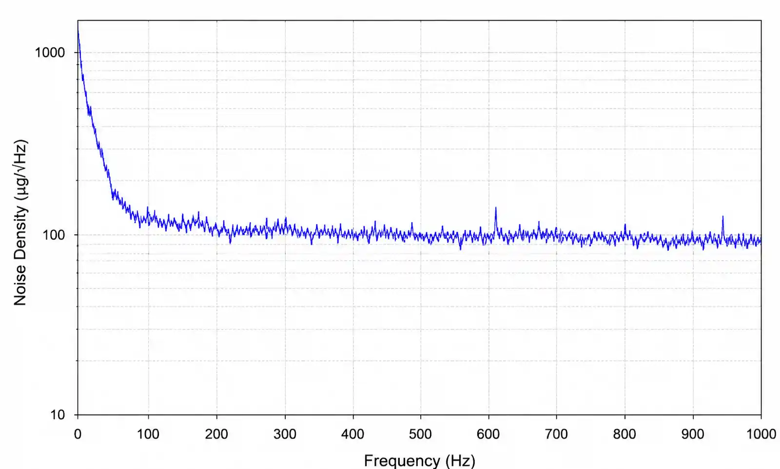
Resolution determines the smallest detectable change in the measured parameter. For precise orientation tracking, you need an accelerometer with sub-mg resolution. For simple motion detection, 10mg resolution suffices. Check the datasheet's resolution specification carefully—some vendors quote RMS noise in µg/√Hz, which requires integration over your signal bandwidth to determine actual resolution.
Noise Performance
Noise limits your system's ability to detect small signals. MEMS sensors exhibit several noise sources: mechanical-thermal noise from the proof mass, electronic noise from readout circuits, and quantization noise from the ADC.
Accelerometers and gyroscopes specify noise density in µg/√Hz or °/s/√Hz. To calculate total noise in your application, multiply noise density by the square root of your signal bandwidth. A gyroscope with 0.01°/s/√Hz noise density used with 100Hz bandwidth produces approximately 0.1°/s RMS noise.
Low-noise designs require careful attention to power supply filtering and PCB layout. We'll cover layout considerations in section 5.
Power Consumption
MEMS sensors are low-power devices, but "low power" means different things across applications. A MEMS accelerometer might consume 10µA in always-on pedometer mode, making it suitable for battery-powered wearables. The same device in high-performance mode might draw 200µA, which is still acceptable for USB-powered devices but problematic for coin-cell applications.
Many MEMS sensors offer multiple power modes. Understanding your duty cycle and performance requirements helps you choose a device and operating mode that balances power and performance. Don't overlook standby current—even a few microamps of standby current matters in ultra-low-power designs.
Output Data Rate and Bandwidth
Output data rate (ODR) determines how frequently the sensor provides updated readings. Your required ODR depends on the signal frequency you need to capture. According to Nyquist theorem, you need at least 2x the highest signal frequency, but in practice 5-10x oversampling provides better results.
For vibration monitoring, you might need ODR of 1kHz or higher. For tilt sensing, 10-50Hz suffices. Higher ODR typically increases power consumption, so select the minimum rate that meets your requirements.
The sensor's analog bandwidth also matters. Some sensors digitally filter the output, which can introduce phase delay. Check whether the sensor's group delay is acceptable for your application, especially in control loops or time-critical measurements.
Temperature Stability and Calibration
MEMS sensors exhibit temperature-dependent offset and sensitivity changes. Accelerometers might see offset drift of 1-2mg/°C and sensitivity drift of 0.01-0.02%/°C. For precision applications, you need factory calibration or in-system calibration to compensate for temperature effects.
Check whether the sensor provides an integrated temperature sensor for drift compensation. Some devices include factory-programmed temperature compensation coefficients stored in non-volatile memory. For critical applications, plan to implement your own multi-point temperature calibration during manufacturing.
Interface and Integration
MEMS sensors typically use I2C, SPI, or analog output interfaces. I2C simplifies multi-device buses but limits throughput to 400kHz (fast mode) or 1MHz (fast-mode plus). SPI supports higher data rates—important for high-ODR applications or when reading multiple sensors simultaneously.
Interrupt functionality matters for power-constrained designs. Look for sensors with programmable motion detection, threshold crossing, or FIFO watermark interrupts. These features let your MCU stay in sleep mode until the sensor detects an event worth processing.
4. Application-Specific Selection Criteria
Different applications prioritize different parameters. Here's how to narrow your selection based on your target market.
Automotive Applications
Automotive MEMS sensors must meet AEC-Q100 qualification standards and operate reliably across -40°C to +125°C (or +150°C for under-hood applications). Crash detection accelerometers need extremely fast response time and high shock survival ratings—often ±2000g or higher mechanical shock tolerance.
Electronic Stability Control (ESC) and rollover detection systems require matched accelerometer and gyroscope sensors with tight calibration tolerances. Many automotive designs use 6-axis inertial measurement units (IMUs) that combine a 3-axis accelerometer and 3-axis gyroscope in a single package.
For tire pressure monitoring systems (TPMS), you need MEMS pressure sensors that handle the harsh environment inside a tire: high centrifugal forces, wide temperature swings, and long-term reliability. Look for devices with proven automotive heritage and robust environmental specifications.
| Parameter | Crash Detection | ESC/Rollover | TPMS |
|---|---|---|---|
| Sensor Type | Accelerometer | 6-axis IMU | Pressure |
| Range | ±50g to ±400g | ±2g accel, ±300°/s gyro | 100-450 kPa absolute |
| Response Time | <0.5ms | <10ms | <10ms |
| Temperature Range | -40 to +105°C | -40 to +105°C | -40 to +125°C |
| Qualification | AEC-Q100 | AEC-Q100 | AEC-Q100 |
| Key Consideration | Shock survival >2000g | Tight cross-axis sensitivity | Long-term stability |
Automotive applications require extensive validation and reliability testing. Factor in 12-18 month qualification timelines when selecting components for automotive designs.
Industrial and IoT Applications
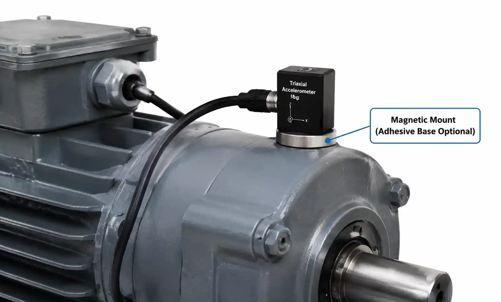
Industrial sensors need long-term stability and operation in challenging environments: vibration, temperature cycling, humidity, and sometimes chemical exposure. Condition monitoring systems use MEMS accelerometers to detect bearing wear, motor imbalance, and machine health degradation.
For vibration analysis, you need accelerometers with wide bandwidth (often DC to several kHz) and low noise. Piezoelectric MEMS accelerometers work well for vibration monitoring because they handle high-frequency content better than capacitive devices. However, they don't measure DC acceleration, so they're unsuitable for tilt sensing.
IoT sensor nodes prioritize ultra-low power consumption and wireless connectivity. A battery-powered environmental monitor might use a MEMS pressure sensor for altitude tracking, a temperature/humidity combo sensor, and a MEMS microphone for acoustic event detection. Total system current in sleep mode might be just a few microamps.
Industrial applications often require 4-20mA current loop outputs or isolated interfaces for harsh electrical environments. Many MEMS sensors don't provide analog current outputs natively, so you'll need signal conditioning circuits.
Consumer Electronics
Consumer devices drove the massive scale-up of MEMS manufacturing over the past decade. Smartphones typically contain 6-10 MEMS sensors: accelerometer, gyroscope, magnetometer, barometric pressure sensor, multiple microphones, and sometimes proximity sensors.
For wearables and fitness trackers, size and power consumption are paramount. Look for accelerometers in sub-2mm packages with 10-20µA operating current. Many modern MEMS accelerometers include hardware pedometers that count steps without MCU intervention, drastically reducing system power.
True wireless earbuds pushed MEMS microphone development forward. These microphones must fit in incredibly small spaces while maintaining good signal-to-noise ratio and handling high sound pressure levels. Dual-microphone designs with beamforming algorithms provide noise cancellation even in noisy environments.
| Application | Key Sensors | Critical Parameters | Typical Package | Power Budget |
|---|---|---|---|---|
| Smartphone | 6-axis IMU, pressure, microphones | Low noise, small size, robust | 2.5x3mm LGA | 50-200µA continuous |
| Fitness Tracker | 3-axis accelerometer | Ultra-low power, pedometer | 2x2mm LGA | 10-30µA average |
| TWS Earbuds | MEMS microphone | SNR >64dB, small size | 3.5x2.6mm | N/A (always-on) |
| Smart Watch | 6-axis IMU, pressure, microphone | Low power, gesture detection | 2.5x3mm LGA | 20-100µA average |
Consumer products face intense cost pressure. High-volume designs benefit from dual-sourcing strategies, but be aware that different vendors' sensors rarely have identical performance characteristics. If you plan to switch suppliers, budget time for re-calibration and firmware tuning.
Medical and Healthcare Devices
Medical applications demand proven reliability, often requiring ISO 13485 quality management systems from suppliers. Wearable medical devices—continuous glucose monitors, cardiac monitors, respiratory trackers—use MEMS sensors for patient monitoring.
For respiratory monitoring, MEMS pressure sensors measure differential pressure across flow restriction elements to calculate breath volume. These sensors need excellent linearity and repeatability across the relevant pressure range (typically ±2 kPa).
Bioimpedance measurements for body composition analysis sometimes use MEMS accelerometers to detect body position, which affects measurement accuracy. These accelerometers need stable offset over temperature because even small tilt errors translate to measurement artifacts.
Medical device timelines are long due to regulatory requirements. Select established MEMS sensors with demonstrated longevity—you don't want your chosen sensor to go obsolete mid-certification.
5. PCB Layout and Integration Considerations
Even the best MEMS sensor will underperform with poor PCB layout. Here's what actually matters based on field experience.
Mechanical Mounting
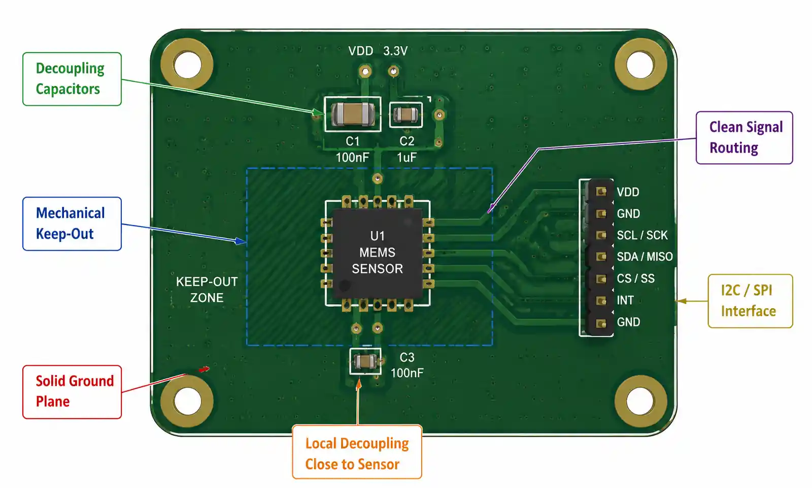
MEMS sensors contain suspended mechanical structures that respond to external forces. Any mechanical stress transferred through the PCB affects sensor readings. Mount MEMS sensors away from board edges, mounting holes, and high-stress areas like connector attachment points.
Use solid copper pour under the sensor for mechanical stiffness. Avoid routing large traces or cutting planes directly under the sensor footprint. If your PCB undergoes significant flexing during assembly or use, consider a smaller board-in-board design that isolates the sensor from mechanical stress.
For hand-soldered prototypes, avoid excessive heat and mechanical pressure during assembly. Reflow profile matters—follow the sensor manufacturer's recommended profile strictly. Excessive peak temperature or prolonged time above liquidus can damage internal structures.
Power Supply Filtering
MEMS sensor analog front-ends are sensitive to power supply noise. Always place a 100nF ceramic capacitor as close as possible to the sensor's VDD pin—ideally within 2-3mm. Use X7R or X5R dielectric, not Y5V, for stable capacitance across temperature.
For noise-critical designs, add a 10µF bulk capacitor near the sensor and consider a ferrite bead or LC filter on the supply line. Check whether your sensor's datasheet specifies power supply rejection ratio (PSRR)—devices with poor PSRR are more vulnerable to supply-coupled noise.
Keep analog supply (VDDA) and digital supply (VDDIO) separate if the sensor provides split supplies. This isolation prevents digital switching noise from corrupting analog measurements.
I2C and SPI Interface Layout
I2C buses should have series resistors (22-33Ω) close to the driving device to reduce signal ringing and EMI. Pull-up resistor values depend on bus capacitance and speed—typical values range from 2.2kΩ to 10kΩ. Stronger pull-ups (lower resistance) support faster speeds but increase power consumption.
For SPI interfaces, keep clock and data traces short and match their lengths to minimize skew. If your SPI clock exceeds 10MHz, use controlled impedance traces and consider termination resistors.
Avoid routing I2C or SPI signals near switching power supplies, high-current traces, or antenna structures. These noise sources couple into sensitive digital interfaces and cause communication errors.
Interrupt and GPIO Routing
MEMS sensor interrupt outputs signal motion detection, threshold crossing, or FIFO status. These interrupts often wake your MCU from sleep, so they must be reliable. Route interrupt signals on inner layers or shield them with ground traces to prevent false triggering from EMI.
Don't use interrupt signals for anything except MCU input—avoid sharing these nets with other functions or devices. Check interrupt pin electrical characteristics: some sensors use open-drain outputs requiring external pull-ups, while others provide push-pull outputs.
Thermal Considerations
MEMS sensors exhibit temperature-dependent offset drift. Avoid placing heat-generating components (power regulators, high-speed processors, RF power amplifiers) near your MEMS sensors. Even a few degrees of self-heating from nearby components can introduce measurement error.
If thermal isolation isn't possible, implement temperature compensation in firmware using the sensor's integrated temperature output. Multi-point calibration across your operating temperature range helps, but it adds manufacturing complexity and cost.
6. Common Design Pitfalls and How to Avoid Them
After reviewing hundreds of MEMS sensor designs, certain mistakes appear repeatedly. Here are the ones that cause the most pain.
Ignoring Mechanical Stress Effects
PCB flexing during manufacturing, assembly, or operation transfers stress into MEMS sensors. This stress manifests as offset shifts or sensitivity changes. I've seen designs where accelerometer readings changed 50mg just from tightening enclosure screws.
The fix: mechanically isolate MEMS sensors from stress concentration points. Use rubber standoffs or gaskets between the PCB and enclosure. If your product experiences high vibration or shock, consider potting the sensor area with compliant material.
Inadequate Power Supply Filtering
Switching regulators and DC-DC converters generate high-frequency noise that couples into MEMS sensor supplies. This noise increases measurement uncertainty and reduces effective resolution. A design might show excellent bench performance with a clean lab supply, then fail in production because the actual system power supply is noisy.
The fix: Always test with your final production power supply, not lab bench supplies. Add LC or RC filtering on sensor supplies if you see noise-related performance degradation. Measure supply noise at the sensor pin with an oscilloscope—don't assume your power supply is clean.
Underestimating Calibration Requirements
Factory calibration covers offset and sensitivity at room temperature, but MEMS sensors drift over temperature, age, and mechanical stress. Applications requiring better than 1% accuracy typically need in-system calibration.
The fix: Design calibration into your manufacturing process from the start. For accelerometers, this means measuring output in multiple orientations (typically six positions) and calculating offset and sensitivity errors. For gyroscopes, measure zero-rate offset at multiple temperatures. Budget 30-60 seconds per unit for calibration—this time adds up in high-volume production.
Mismatched Sensor and Application Requirements
Choosing a high-performance sensor when a basic device suffices wastes money and power. Conversely, selecting an under-specified sensor to hit cost targets creates performance problems that might not surface until after production starts.
The fix: Write down your actual requirements for range, resolution, noise, bandwidth, and power before shopping for sensors. Leave margin for manufacturing variation and environmental extremes, but don't over-specify by 10x just to be safe. Prototype with your target sensor, not a development board, to validate real-world performance.
Firmware Integration Assumptions
MEMS sensor datasheets provide register maps and communication protocols, but they rarely explain the nuances of initializing the device correctly, handling error conditions, or optimizing power consumption. First-time users often struggle with proper configuration.
The fix: Use vendor-provided driver code as a starting point, even if you plan to write custom firmware. The vendor code usually handles initialization sequences, timing requirements, and configuration quirks that aren't obvious from the datasheet. Join vendor developer forums or contact FAE support if you hit integration issues.
Ignoring Long-Term Stability
MEMS sensors drift over time due to material relaxation, packaging stress evolution, and environmental exposure. A sensor that works perfectly at initial production might show significant offset shift after six months in the field.
The fix: Request long-term stability data from your sensor vendor. For critical applications, implement periodic self-calibration or require users to perform calibration procedures. Some advanced MEMS sensors include built-in self-test and calibration features that help maintain accuracy over product lifetime.
7. FAQ
What's the difference between analog and digital output MEMS sensors?
Analog output sensors provide a voltage proportional to the measured parameter, requiring an external ADC for digital processing. Digital output sensors integrate an ADC and communicate via I2C or SPI. Digital sensors simplify design and reduce component count, but analog sensors can offer lower latency and are easier to interface with analog signal chains. For modern designs with MCU integration, digital sensors are usually the better choice unless you have specific analog processing requirements.
How do I calculate the required MEMS accelerometer range for my application?
Add up all acceleration sources your device experiences: gravity (1g), intended motion (e.g., 3g for gesture detection), and shock/impact events (can be 10-100g depending on product). Add 20-30% margin for unexpected conditions. For example, a fitness tracker might experience 1g gravity + 2g from arm movement + 10g drop shock, suggesting a ±16g sensor with margin. Don't forget that inclinometer applications need to resolve gravity components, so higher range reduces tilt resolution.
Can I use the same MEMS sensor across multiple product variants with different requirements?
Sometimes, but be careful. Many MEMS sensors offer programmable ranges, filter settings, and power modes that let one device serve multiple use cases. However, optimal performance usually requires purpose-designed sensors. A low-noise, low-power accelerometer for step counting won't handle high-g crash detection well. Evaluate whether a single sensor truly meets all requirements or whether you're compromising performance to reduce BOM complexity.
What causes MEMS gyroscope zero-rate offset drift?
Zero-rate offset (the output reading when the sensor isn't rotating) drifts due to temperature changes, mechanical stress, and inherent random walk. Temperature is the biggest contributor—gyro offset typically shifts 0.01-0.1°/s per degree Celsius. This drift compounds in dead-reckoning applications, causing position estimates to diverge over time. Better gyroscopes have lower temperature coefficients and built-in temperature compensation, but no MEMS gyro is drift-free. Long-term operation requires periodic re-zeroing using external references (GPS, magnetometer, or stationary detection).
Should I implement my own sensor fusion algorithm or use vendor libraries?
Vendor-provided sensor fusion algorithms (like Bosch's BSX, ST's MotionFX, or InvenSense's Digital Motion Processor) save significant development time and are well-tested across millions of units. Use them unless you have specific requirements they don't meet or you're building competitive advantage through custom algorithms. Implementing robust sensor fusion from scratch requires deep understanding of Kalman filtering, quaternion math, and extensive real-world testing. Budget 3-6 months of engineering time if going custom.
How do I select between capacitive and piezoelectric MEMS accelerometers?
Capacitive MEMS accelerometers measure DC to several kHz, consume low power, and dominate consumer/industrial applications. Piezoelectric accelerometers have AC-coupled outputs (can't measure static tilt), higher bandwidth (DC to 10kHz+), and better performance in vibration monitoring. Choose capacitive for tilt sensing, orientation tracking, or pedometry. Choose piezoelectric for vibration analysis, impact detection, or high-frequency structural monitoring.
What testing should I perform to validate MEMS sensor integration?
At minimum: verify communication (read WHO_AM_I register or equivalent), check output at known orientations (accelerometer), verify temperature compensation across your operating range, test interrupt functionality, measure power consumption in all operating modes, and perform ESD testing on sensor pins. For production, implement automated calibration and functional tests. Budget for environmental testing (temperature cycling, humidity exposure, mechanical shock) if your application has reliability requirements beyond typical consumer use.
How do supply chain disruptions affect MEMS sensor availability?
MEMS sensors require specialized fabrication processes, and most vendors operate their own fabs (STMicroelectronics, Bosch Sensortec) or use dedicated MEMS foundries (Silex, Teledyne DALSA). This vertical integration provides good supply chain stability compared to purely fabless companies, but lead times can still extend to 20-30 weeks during high-demand periods. Establish relationships with authorized distributors, commit to volume forecasts, and maintain 3-6 months of buffer stock for production designs. Consider dual-sourcing for high-volume products, but validate performance carefully—MEMS sensors from different vendors rarely perform identically even with similar specifications.
8. Conclusion
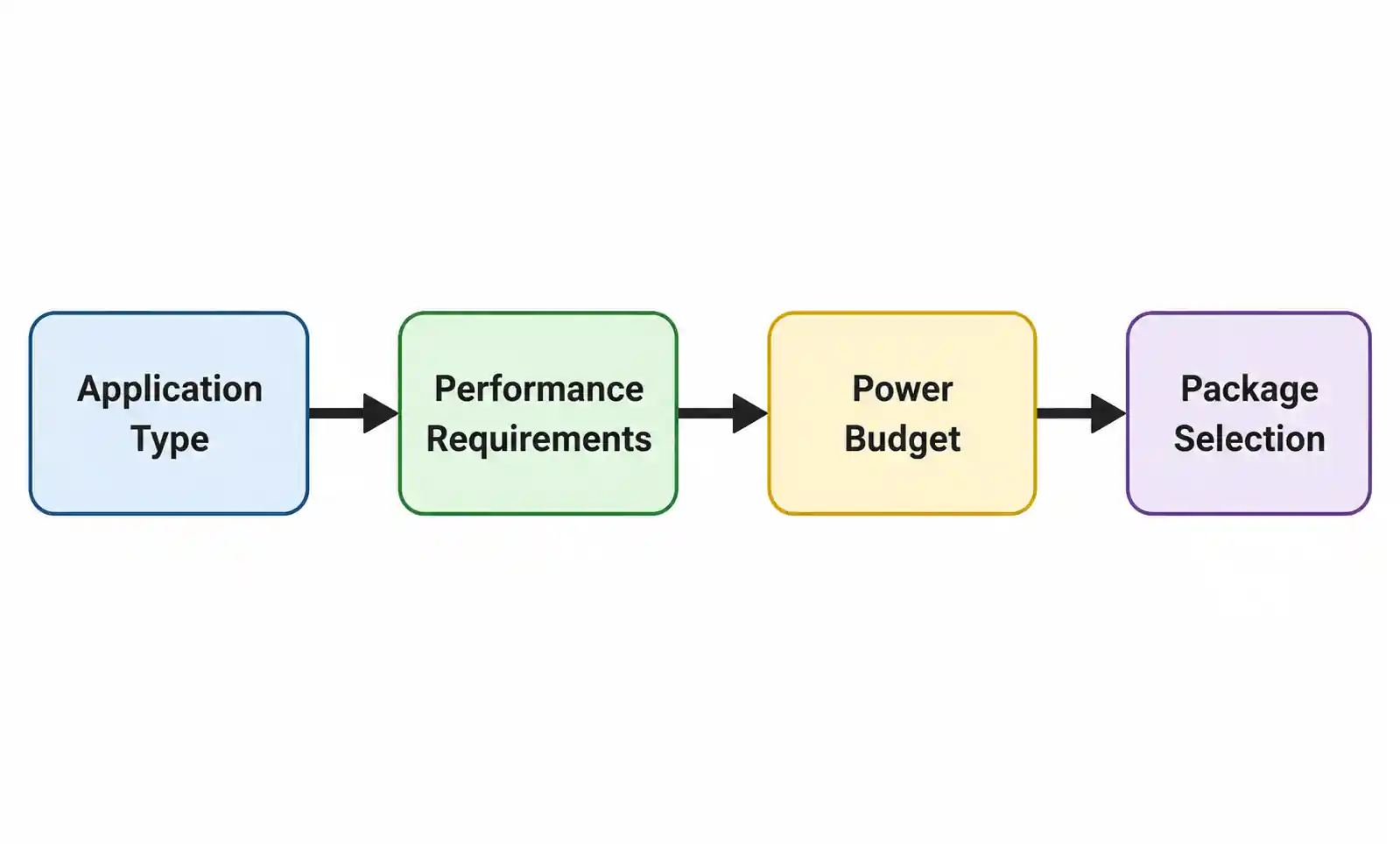
Selecting the right MEMS sensor requires balancing technical performance, power consumption, cost, and supply chain considerations. Start by clearly defining your application requirements: measurement range, resolution, bandwidth, temperature range, and power budget. Use these requirements to narrow the field to a handful of candidates, then prototype with your top choices to validate real-world performance.
Don't underestimate integration challenges—PCB layout, mechanical stress isolation, and firmware integration all impact whether your MEMS sensor delivers its datasheet performance in your final product. Budget time for calibration development and validation testing, especially if your application requires better than 5% accuracy.
For applications in automotive, medical, or industrial markets, engage with sensor vendors early in your design cycle. FAE support can help you navigate qualification requirements, understand long-term stability characteristics, and optimize your design for manufacturability.
If you're finalizing component selection for an upcoming project, download detailed datasheets for your shortlisted sensors and review application notes specific to your target market. Most MEMS vendors provide reference designs and evaluation boards that let you prototype quickly. For complex integration questions or custom requirements, contact technical support—vendors want your design to succeed and are generally responsive to genuine engineering inquiries.