




Relay vs Solid-State Switch: Selection Guide for Control Applications
Table of Contents
- Introduction
- Operating Principles: Mechanical vs Semiconductor Switching
- Performance Comparison
- Critical Selection Parameters
- Thermal Management for Solid-State Switches
- Application-Specific Selection
- Cost Analysis
- Common Selection Mistakes
- FAQ
- Conclusion
Introduction
Selecting between electromechanical relays (EMR) and solid-state switches (SSR) determines whether your control system operates for months or decades. The fundamental difference—physical contact motion versus semiconductor switching—creates distinct performance profiles that determine application suitability.
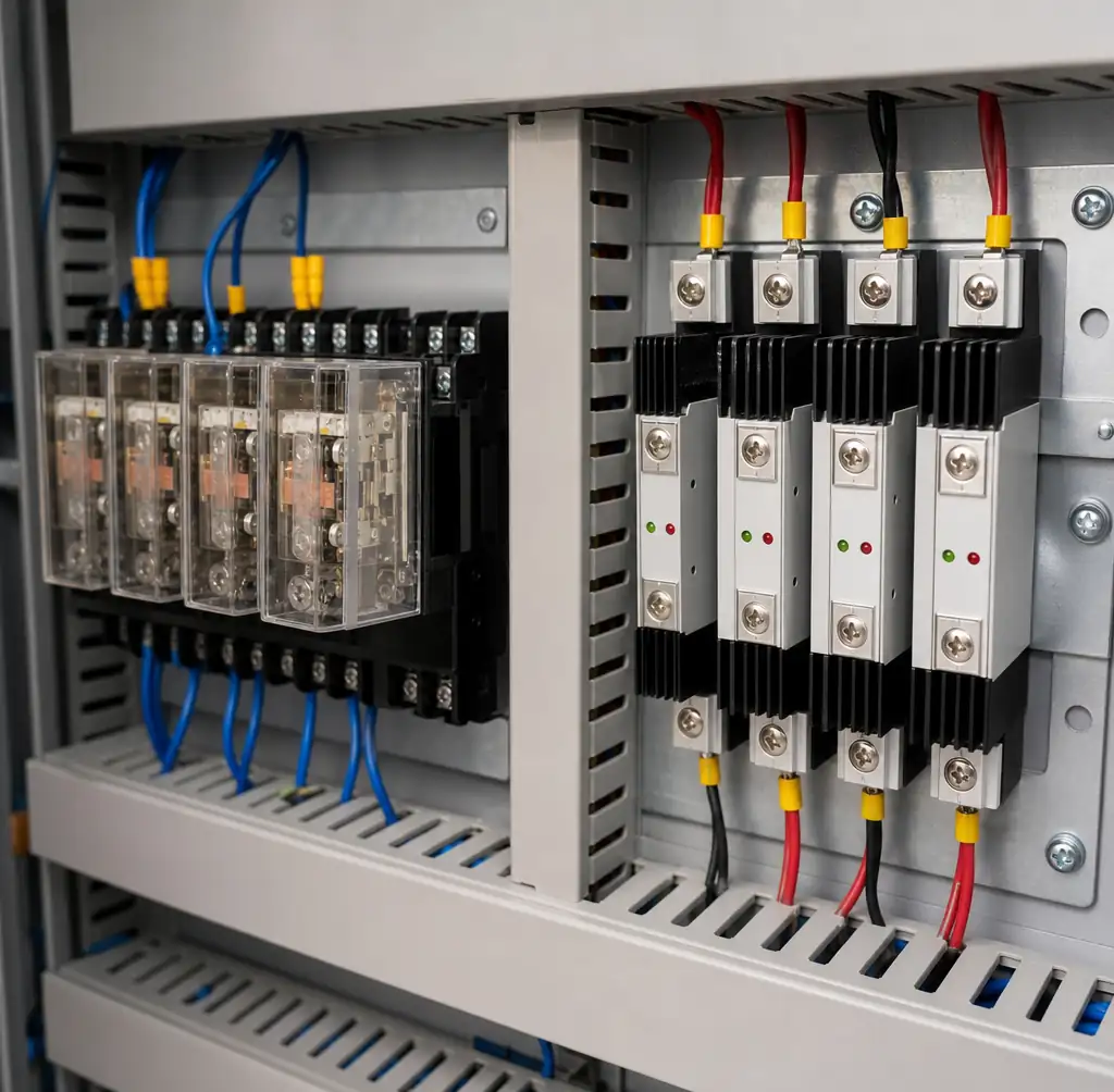 Industrial control panel showing both electromechanical relays and solid-state switches mounted side by side
In industrial applications with switching frequency exceeding 100 cycles daily, mechanical relays fail within months while solid-state switches operate for years. Applications requiring true galvanic isolation and infrequent switching favor mechanical simplicity. Understanding these trade-offs prevents costly field failures.
Operating Principles: Mechanical vs Semiconductor Switching
Electromechanical relays use electromagnetic coils to physically move contacts, creating or breaking electrical connections. This mechanical action provides true air-gap isolation (2-5mm) between control and load circuits. Silver alloy contacts offer low resistance, but arcing during switching gradually transfers material between contacts until failure.
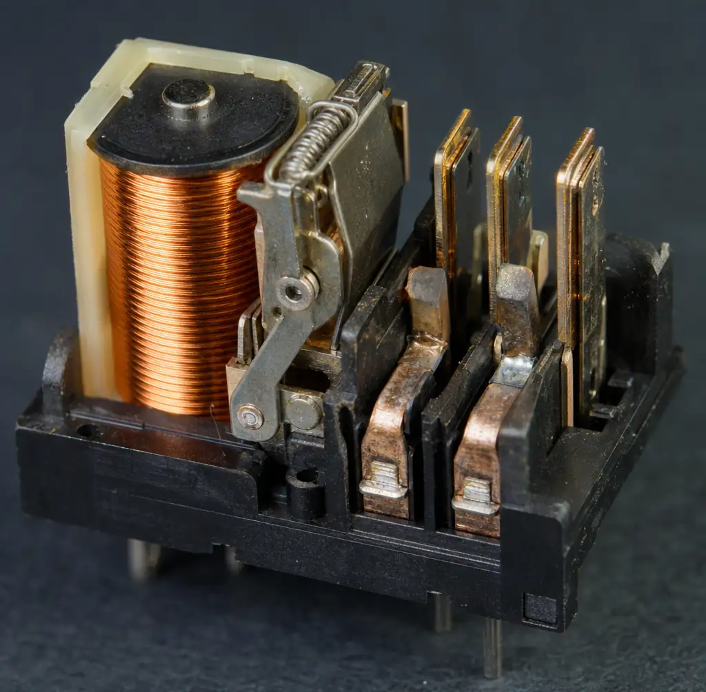 Close-up photograph of electromechanical relay internal mechanism showing coil, armature, and contact assembly
Contact bounce creates multiple make-break cycles lasting 1-5 milliseconds. Switching speed is limited to 5-15 milliseconds by mechanical inertia. A relay switching 6 cycles per minute continuously consumes half its rated lifetime in just 29 days—mechanical wear is unavoidable.
Solid-state switches use semiconductor devices (TRIACs, thyristors, MOSFETs, or IGBTs) controlled through optical isolation. An LED-phototransistor pair provides electrical isolation without mechanical motion. The semiconductor remains in the circuit path even when "off," creating fundamental differences from mechanical contacts.
Zero-crossing switching detects AC waveform polarity and switches only at voltage zero-crossing. This eliminates inrush current spikes that occur when mechanical contacts close at peak voltage, reducing electromagnetic interference by 60-80% in industrial temperature control systems.
Performance Comparison
Performance differences between mechanical and solid-state switching are substantial and measurable.
| Parameter | Electromechanical Relay | Solid-State Switch | Practical Impact |
|---|---|---|---|
| Switching Speed | 5-15 milliseconds | 10 microseconds - 1 millisecond | SSR enables PWM and fast control |
| Mechanical Lifespan | 50,000 - 500,000 cycles | No mechanical wear | SSR eliminates scheduled replacement |
| Contact Bounce | 1-5 milliseconds | Zero bounce | SSR prevents bounce-induced errors |
| Acoustic Noise | Audible click (50-70 dB) | Silent operation | SSR required in sensitive environments |
| Maximum Frequency | <10 Hz continuous | Up to 10 kHz | SSR handles high-speed applications |
Industrial heater control switching 10 times per minute sees relay failures within 4-6 months, while equivalent SSR installations operate 5+ years without degradation. Semiconductor junctions have no mechanical wear, making cycle count effectively irrelevant until thermal stress causes parameter drift.
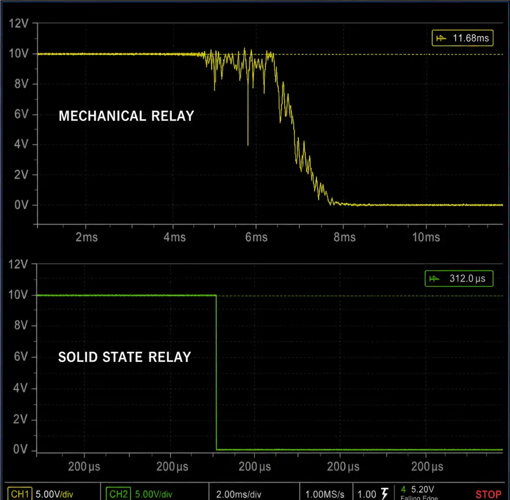 Oscilloscope screen capture comparing switching speed of mechanical relay versus solid-state switch
Failure modes differ critically. Mechanical relays typically fail open—worn contacts no longer close reliably. Solid-state switches usually fail shorted—semiconductor breakdown creates permanent conduction. This distinction affects safety-critical designs requiring load de-energization on component failure.
Critical Selection Parameters
Isolation and Leakage Current
Mechanical relays provide galvanic isolation through 2-5mm air gaps, yielding 2-10 kV isolation voltage. This complete electrical separation protects control circuits from load transients.
Solid-state switches achieve 2.5-7.5 kV optical isolation, but output semiconductors remain electrically connected. Off-state leakage current ranges from 100 microamperes to several milliamperes. Mechanical relays exhibit essentially zero leakage—picoamperes only.
This leakage prevents complete load de-energization, causing issues with LED lighting, sensitive electronics, or safety interlocks requiring verified zero current. For absolute isolation during maintenance or faults, mechanical relays provide superior protection.
Voltage Drop and Power Dissipation
Mechanical relay contacts exhibit <50-100 milliohm resistance. A 30A relay drops 1.5-3V, dissipating 45-90 watts with no external cooling required.
Solid-state switches dissipate 1.0-1.6V × load current. A 30A load creates 30-48 watts requiring substantial heat sinking. Inadequate thermal management accelerates failure—90% of SSR failures trace to thermal issues.
| Load Current | SSR Voltage Drop | Power Dissipation | Heat Sink Requirement |
|---|---|---|---|
| 10A | 1.2V | 12W | Small heat sink or forced air |
| 25A | 1.4V | 35W | Medium heat sink, natural convection |
| 40A | 1.5V | 60W | Large heat sink or active cooling |
| 75A | 1.6V | 120W | Substantial heat sink with forced air |
Thermal Management for Solid-State Switches
SSRs dissipate approximately 1-1.4 watts per ampere of switched current. Heat must be removed continuously to maintain junction temperature within specifications. Heat sink selection should calculate power dissipation from actual voltage drop, then use manufacturer derating curves.
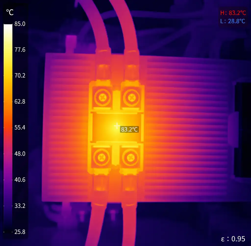 Oscilloscope screen capture comparing switching speed of mechanical relay versus solid-state switch
Never mount SSRs in enclosed areas without ventilation. Never mount to plastic surfaces or painted metal—paint creates thermal insulation. Clean metal mounting with thermal interface material provides lowest thermal resistance.
Operating temperature directly affects current rating. Most datasheets show current decreasing linearly above 40°C. An SSR rated 40A at 25°C might derate to 25A at 70°C ambient. Operating beyond thermally-derated limits causes junction temperature rise that exponentially accelerates degradation.
Application-Specific Selection
High-Frequency Switching and Temperature Control
Solid-state switches dominate applications requiring rapid, repetitive switching. PWM motor control, LED dimming, and proportional heating demand 100 Hz to 10 kHz switching that mechanical relays cannot sustain.
Industrial temperature control systems using PID controllers exemplify SSR advantages. Controllers modulate heater power by varying PWM duty cycle, switching thousands of times per hour. Mechanical relays fail within weeks, while SSRs operate indefinitely with proper thermal management. Relay failures cause 68% of PID controller shutdowns—converting to SSRs eliminates this failure mode.
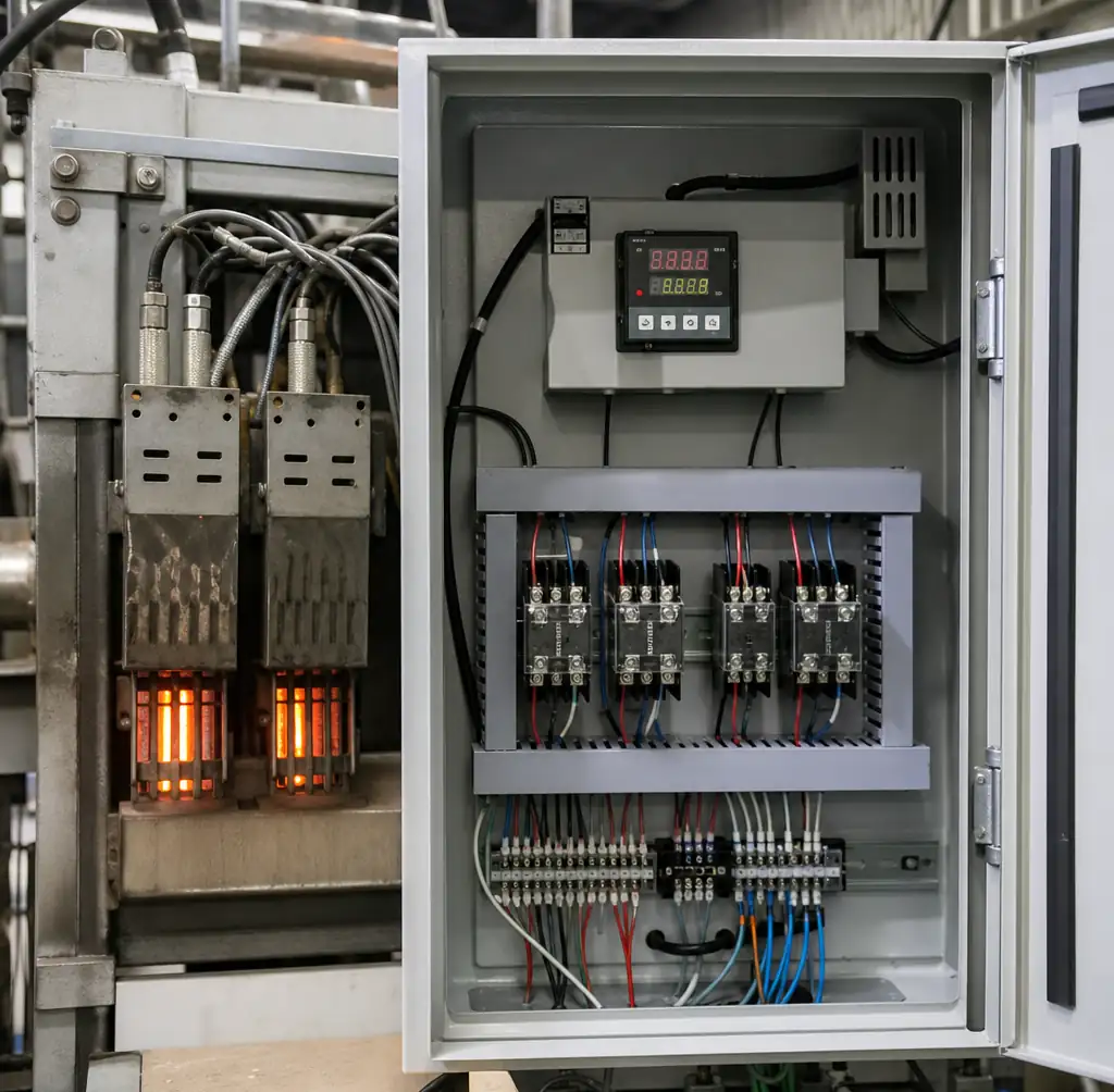 Industrial electric heater installation with solid-state relay control system
Safety Interlocks and Infrequent Switching
For applications switching occasionally—safety interlocks, emergency stops—where true galvanic isolation and fail-safe behavior matter more than cycle life, mechanical relays provide superior value. Air-gap isolation guarantees complete separation critical for safety circuits where semiconductor leakage could create hazards.
Motor Starting Considerations
Motor starting requires analyzing inrush characteristics. Mechanical relays handle motor inrush (6-8× running current) without issue. Solid-state switches must be oversized—often 3-4× motor running current—to handle inrush without thermal damage.
For continuous operation with infrequent starts, mechanical contactors remain cost-effective. For motors requiring frequent reversing or variable-speed control, SSRs provide superior performance despite higher cost.
Cost Analysis
A 30A industrial relay costs $8-15, while an equivalent SSR costs $40-70—a 4-5× price multiplier. For low-volume applications or infrequent switching, mechanical relays provide adequate performance at minimal cost.
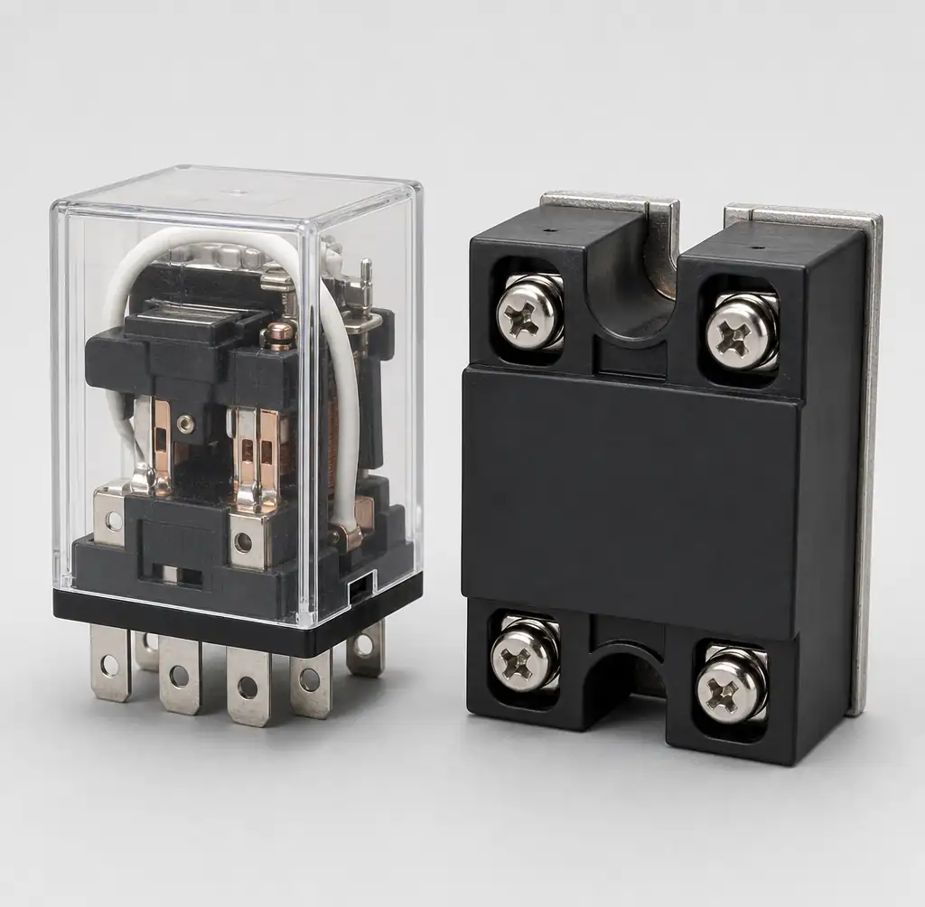 Side-by-side photograph comparing physical size and cost between equivalent relay and SSR
Total cost of ownership changes this analysis for high-cycle applications. A relay requiring replacement every 6-12 months incurs labor costs, inventory costs, and potential downtime. An SSR operating 5-10 years without maintenance eliminates recurring expenses, justifying higher initial investment.
Favor mechanical relays when:
- Switching frequency <10 cycles per day
- True galvanic isolation is safety-critical
- Budget constraints dominate
- Minimal voltage drop required
- Regular maintenance access available
Favor solid-state switches when:
- Switching frequency >100 cycles per day
- Silent operation required
- PWM or high-speed switching needed
- Long maintenance intervals mandatory
Common Selection Mistakes
Undersizing SSRs for cost causes premature failures. Selecting based solely on load current without calculating power dissipation leads to junction overtemperature. Always verify maximum current at actual operating temperature with proposed heat sink.
Ignoring relay mechanical lifetime in high-cycle applications. A 100,000-cycle relay fails predictably after that count regardless of electrical load. For continuous operation at moderate frequency, this arrives within months.
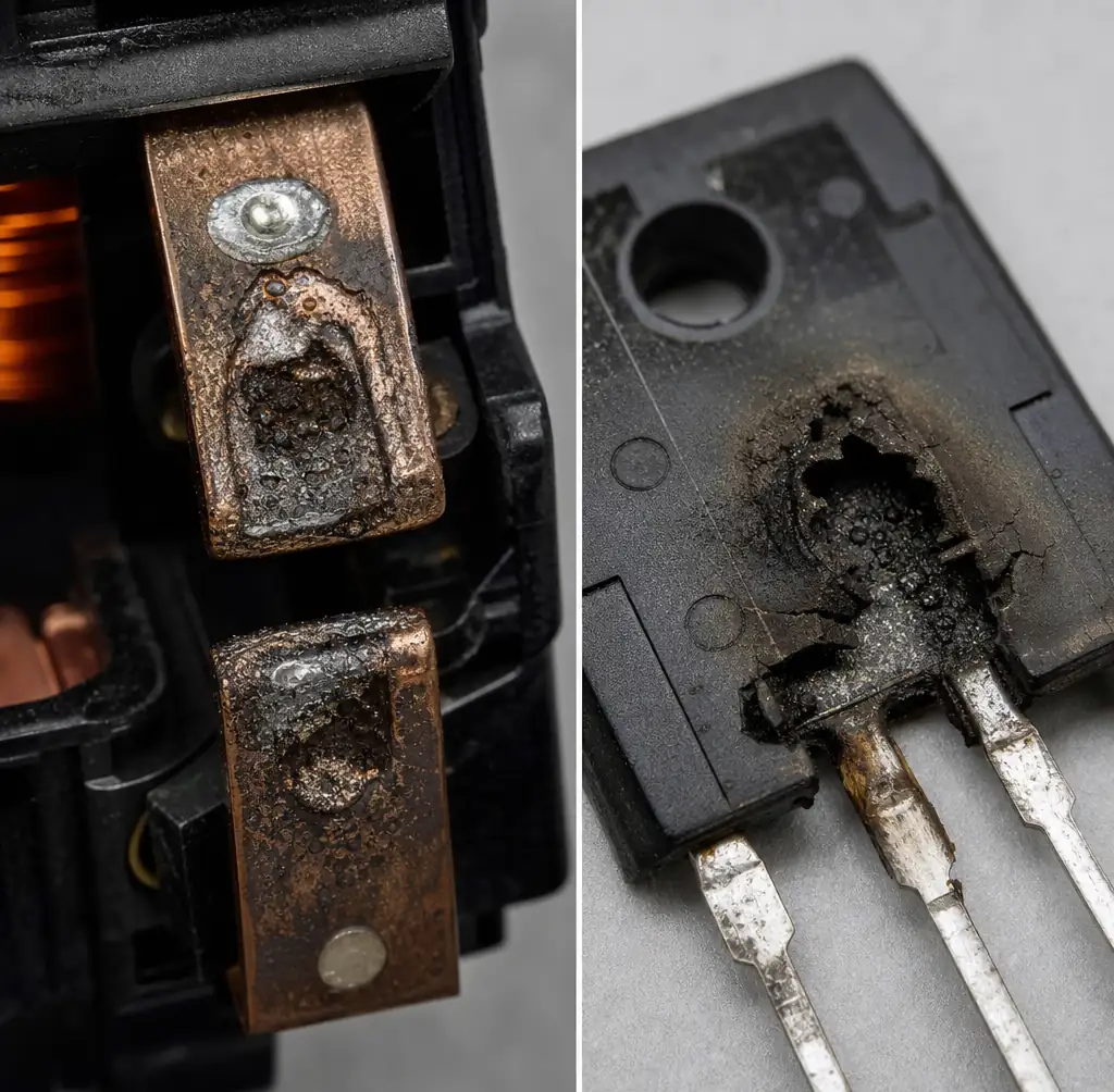 Macro photograph showing worn and pitted relay contacts versus failed SSR semiconductor
Assuming SSRs provide complete isolation like mechanical contacts. Output semiconductors remain in circuit when off, conducting leakage current preventing full de-energization. For safety interlocks requiring verified zero current, mechanical relays provide superior isolation.
Neglecting failure mode differences in safety-critical designs. Relay contacts typically fail open from wear. SSRs typically fail shorted from semiconductor breakdown. Safety circuits requiring guaranteed de-energization must account for this through redundant switching.
Selecting based on datasheet ratings without derating. Both relay and SSR ratings assume ideal conditions. Real applications require 50-70% derating for motor loads, incandescent lamps, or capacitive loads. SSR temperature derating becomes critical above 40°C ambient.
FAQ
Q: Can I replace a mechanical relay with an SSR directly?
Not always. Verify three parameters: First, confirm the SSR can handle your load type—motors and incandescent lamps have high inrush requiring 3-4× SSR oversizing. Second, check that off-state leakage won't affect your load—sensitive electronics may show effects. Third, ensure control signal voltage matches SSR input specifications.
Q: Why does my SSR get extremely hot?
Calculate power dissipation: load current × SSR voltage drop (typically 1.2-1.6V). A 30A load creates 36-48W heat. Verify heat sink thermal resistance using manufacturer derating curves. Check mounting surface cleanliness and thermal interface application. Verify ambient temperature assumptions.
Q: How do I calculate relay lifespan?
Find rated mechanical lifetime in datasheet (typically 100,000-500,000 cycles). Divide by daily switching cycles. A 100,000-cycle relay switching 10 times daily lasts approximately 27 years. The same relay switching 100 times daily fails after 1,000 days (2.7 years).
Q: What causes relay contact welding?
Excessive inrush current or arc energy welds contacts together. This occurs with motor loads, incandescent lamps, or capacitive loads creating momentary spikes exceeding steady-state current. Proper selection requires examining both steady-state and inrush ratings.
Q: Can SSRs switch DC loads effectively?
Yes, but select SSRs specifically rated for DC switching. TRIAC-based SSRs work only with AC—they require current zero-crossing to turn off. MOSFET-based SSRs handle DC loads with lower voltage drop. Never attempt DC switching with AC-rated SSRs.
Q: How do I select between AC and DC rated SSRs?
AC-rated SSRs using TRIACs provide zero-crossing switching and work only with AC loads. DC-rated SSRs use MOSFETs and handle DC loads with lower voltage drop but lack zero-crossing capability. For universal applications, select DC-rated SSRs but verify AC application requirements.
Conclusion
Selecting between electromechanical relays and solid-state switches depends on understanding their architectural differences. Mechanical relays offer unbeatable cost, true galvanic isolation, and zero voltage drop for low-frequency applications. Solid-state switches provide unlimited cycle life, silent operation, and microsecond switching for PWM control and high-frequency applications.
The decision framework: analyze switching frequency, isolation requirements, budget constraints, and failure mode criticality. Applications switching <10 times daily favor mechanical relays unless noise sensitivity demands solid-state. High-frequency switching >100 cycles daily justifies solid-state investment through extended maintenance intervals.
Neither technology is universally superior—each excels in its appropriate domain. Proper selection matches technology strengths to application requirements. The most reliable control systems strategically employ both technologies, using mechanical relays where isolation and cost matter most, and solid-state switches where cycle life and speed determine success.
For guidance on component selection for control applications, or to discuss specific switching requirements, contact our procurement team for application-specific recommendations.
