


Variable Capacitor Selection Guide: Types, Applications, and Design Considerations
Variable capacitors remain critical components in RF circuit design, tuning applications, and precision analog systems. Unlike fixed capacitors, these components allow engineers to adjust capacitance values dynamically, enabling functions like frequency tuning, impedance matching, and filter optimization. This guide helps design engineers, RF specialists, and product developers select the right variable capacitor for their specific application requirements.
Table of Contents
- What is a Variable Capacitor and How It Works
- Key Technical Parameters Explained
- Types of Variable Capacitors and Their Applications
- How to Choose the Right Variable Capacitor
- Design Considerations and Common Pitfalls
- Supply Chain and Sourcing Considerations
- FAQ
- Conclusion and Next Steps
1. What is a Variable Capacitor and How It Works
A variable capacitor is an adjustable passive component that allows controlled changes in capacitance within a specified range. The capacitance adjustment mechanism varies by type—mechanical variable capacitors use rotating plates or screws, while electronic variants rely on voltage-controlled semiconductor junctions (varactors) or MEMS technology.
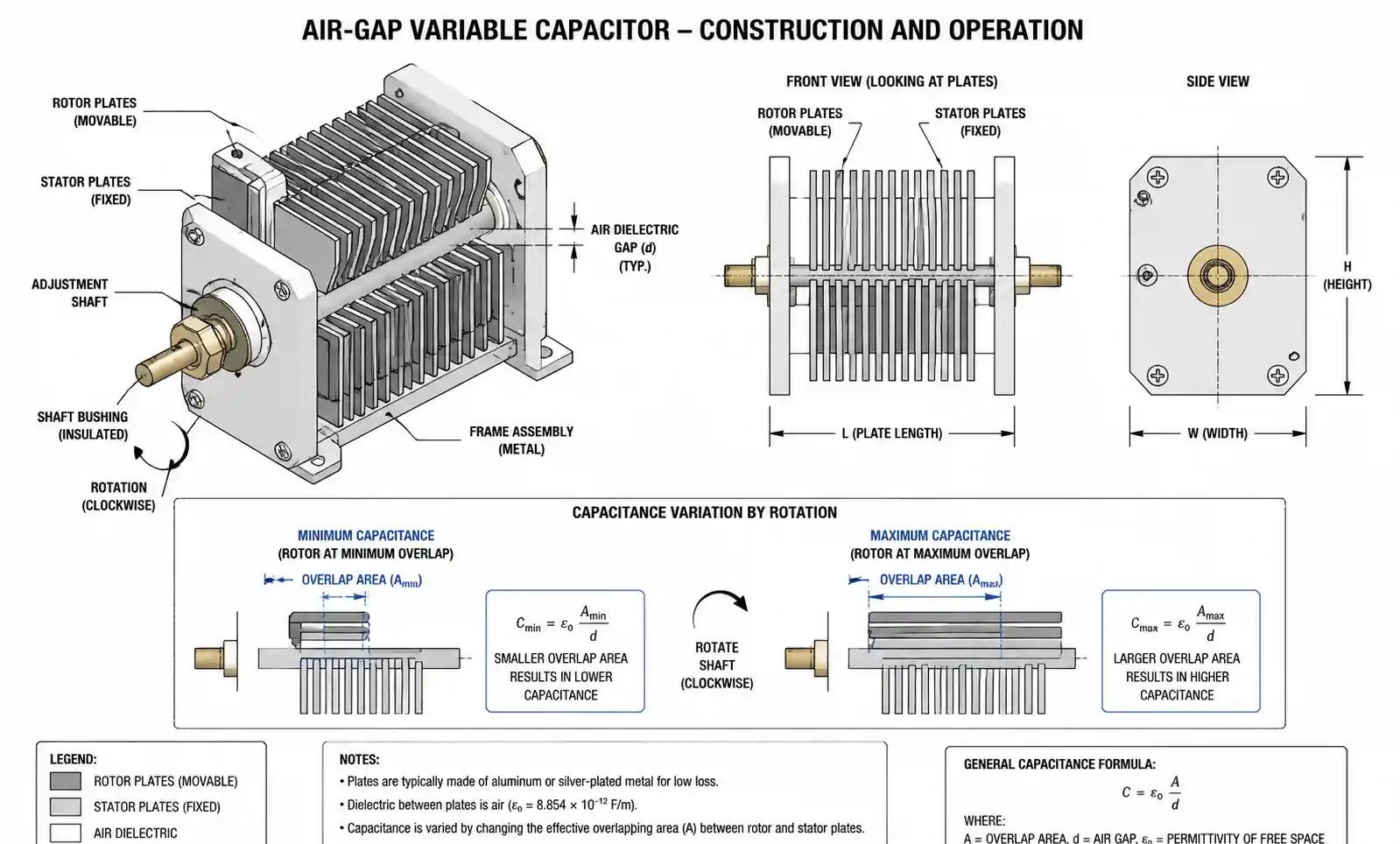
The fundamental operation principle follows the standard capacitance equation C = εA/d, where capacitance changes by altering either the effective plate area (A) or the distance between plates (d). In air-gap variable capacitors, rotating one set of plates (rotor) relative to a fixed set (stator) changes the overlapping area. In trimmer capacitors, a screw mechanism adjusts the plate separation distance. Varactor diodes achieve capacitance variation by modifying the depletion region width through reverse bias voltage.
Variable capacitors serve three primary functions in electronic systems: frequency tuning in RF circuits, impedance matching in antenna systems, and phase adjustment in oscillator designs. Their ability to provide real-time capacitance adjustment makes them indispensable in applications where circuit parameters must adapt to changing conditions or user requirements.
2. Key Technical Parameters Explained
Understanding variable capacitor specifications requires careful attention to parameters that directly affect circuit performance. The capacitance range defines the minimum and maximum achievable values, typically expressed as Cmin and Cmax. The capacitance ratio (Cmax/Cmin) indicates tuning range—higher ratios provide broader frequency coverage in tuning applications. For RF applications, a capacitance ratio of 5:1 to 10:1 is common, while precision trimming applications may use narrower ranges.
Quality factor (Q) measures the efficiency of energy storage relative to energy loss. High-Q variable capacitors minimize resistive losses, which is critical in RF filters and resonant circuits where insertion loss directly impacts system performance. At frequencies above 100 MHz, look for Q values exceeding 1000. Temperature coefficient (TC) specifies capacitance drift with temperature, expressed in ppm/°C. Applications requiring stable frequency response across temperature ranges demand low TC values, typically below ±100 ppm/°C.
Voltage rating determines the maximum DC and AC voltages the component can withstand without breakdown. RF applications must consider both the DC bias voltage and the RF voltage swing. The equivalent series resistance (ESR) contributes to power dissipation and signal loss, particularly in high-frequency circuits. Lower ESR values yield better performance in demanding RF applications.
Tuning linearity describes how capacitance changes relative to the adjustment mechanism's position. Linear tuning simplifies calibration and improves tuning precision in applications like radio receivers. Non-linear tuning characteristics can complicate frequency scaling but may be acceptable in applications where digital calibration compensates for the non-linearity.
| Parameter | Typical Range | Critical For | Design Impact |
|---|---|---|---|
| Capacitance Range | 1 pF – 500 pF | RF tuning, oscillators | Determines frequency coverage |
| Quality Factor (Q) | 200 – 2000+ @ 1 MHz | Filter selectivity, loss | Higher Q = lower insertion loss |
| Voltage Rating | 50 V – 1000 V | Power handling | Must exceed peak RF + DC voltage |
| Temperature Coefficient | ±50 to ±500 ppm/°C | Frequency stability | Lower TC = better temp stability |
| ESR | 0.05 Ω – 2 Ω | High-frequency performance | Lower ESR = less signal loss |
| Tuning Resolution | 0.01 pF – 1 pF | Precision applications | Finer resolution = better control |
The table above shows how parameter selection directly impacts circuit performance. In high-Q RF filter designs, both the Q factor and ESR become primary selection criteria. For frequency synthesizers requiring precise control, tuning resolution and linearity dominate the decision. Understanding which parameters matter most for your specific application prevents over-specification (which increases cost) and under-specification (which compromises performance).
3. Types of Variable Capacitors and Their Applications
Air-Gap Variable Capacitors
Air-gap variable capacitors use atmospheric air as the dielectric between rotating and fixed metal plates. This construction provides excellent high-frequency performance with minimal dielectric losses and high Q factors exceeding 1500 at 100 MHz. The absence of solid dielectric eliminates dielectric absorption, making air-gap types ideal for precision RF applications.
These capacitors excel in radio transmitters, antenna tuners, and high-power RF applications where voltage ratings from 500V to several kilovolts are common. The mechanical robustness supports frequent adjustment cycles without performance degradation. However, the relatively large physical size limits their use in compact modern designs. Typical capacitance ranges span 10 pF to 500 pF with tuning ratios of 10:1 or higher.
Trimmer Capacitors
Trimmer capacitors provide semi-fixed capacitance adjustment for circuit calibration and fine-tuning during manufacturing or maintenance. These compact components use ceramic, glass, or PTFE dielectrics with adjustment accomplished via a screw mechanism. Single-turn and multi-turn versions offer different resolution levels—multi-turn trimmers provide finer control for precision applications.
Common applications include oscillator frequency adjustment, filter trimming, and impedance matching network calibration. Ceramic trimmers dominate cost-sensitive applications with capacitance ranges from 1 pF to 100 pF. Glass and air trimmers serve high-stability requirements where temperature coefficient below ±30 ppm/°C is essential. The sealed construction protects against environmental contamination, maintaining stability over the product lifetime.
Varactor Diodes (Electronic Variable Capacitors)
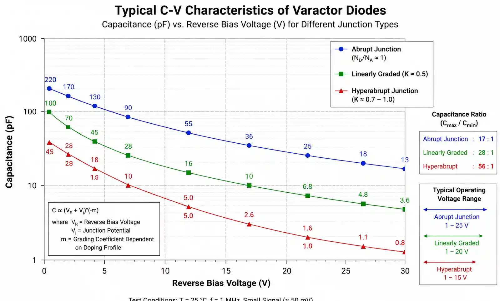
Varactor diodes achieve capacitance variation through voltage control rather than mechanical adjustment. These semiconductor junctions behave as voltage-dependent capacitors, with capacitance decreasing as reverse bias voltage increases. The relationship typically follows C ∝ V^(-0.5) for abrupt junction varactors, though hyperabrupt variants offer steeper tuning curves approaching C ∝ V^(-1) or higher.
Electronic tuning enables fast, remote-controlled frequency adjustment essential for frequency synthesizers, voltage-controlled oscillators (VCOs), and electronically tuned RF filters. Varactors support modulation bandwidths extending to several GHz, far exceeding mechanical variable capacitor capabilities. The absence of moving parts eliminates mechanical wear, but introduces challenges including temperature sensitivity and potential non-linearity requiring compensation circuitry.
| Varactor Type | Capacitance Ratio | Q Factor @ 100 MHz | Typical Applications |
|---|---|---|---|
| Abrupt Junction | 3:1 to 5:1 | 200 – 500 | General-purpose VCOs, FM modulators |
| Hyperabrupt Junction | 10:1 to 15:1 | 100 – 300 | Wide-range tuning, TV tuners |
| Step Recovery | 2:1 to 4:1 | 500 – 1000 | Low-noise oscillators, harmonic generators |
Varactor selection requires careful attention to the capacitance-voltage characteristic (C-V curve), which determines tuning range and linearity. Applications requiring linear frequency tuning often need linearization circuits or lookup tables to compensate for the inherent non-linear C-V relationship.
MEMS Variable Capacitors
MEMS (Microelectromechanical Systems) variable capacitors represent the newest technology, combining mechanical adjustment principles with semiconductor fabrication techniques. Electrostatic actuation moves microscale mechanical structures to change capacitance. These devices offer exceptional Q factors exceeding 100 at GHz frequencies, compact size, and low power consumption.
MEMS variable capacitors address the growing demand for miniaturized, high-performance RF components in mobile devices, IoT sensors, and 5G infrastructure. Typical capacitance ranges span 0.5 pF to 20 pF with switching speeds in the microsecond range. The technology remains relatively expensive compared to traditional variable capacitors, limiting adoption primarily to applications where size, performance, and integration density justify the cost premium.
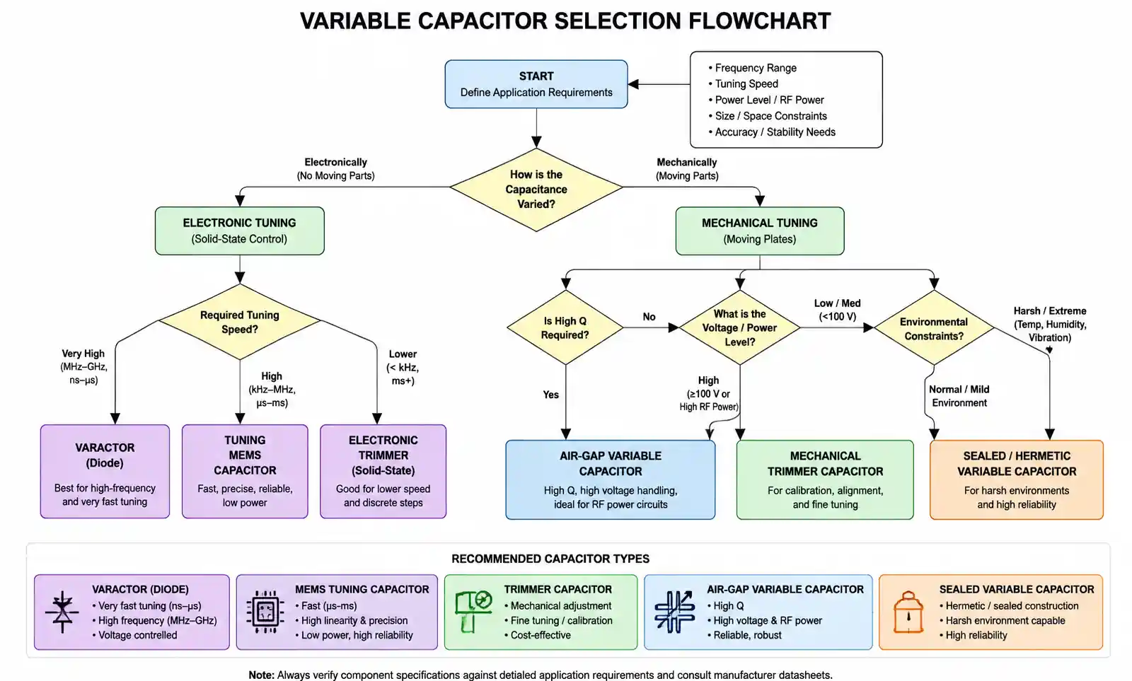
4. How to Choose the Right Variable Capacitor
Selecting the appropriate variable capacitor requires a systematic evaluation of application requirements against component specifications. Start by defining the required capacitance range based on the frequency tuning range or impedance matching requirements. For RF oscillator applications, use the equation f = 1/(2π√LC) to calculate the capacitance range needed to achieve your target frequency span with your selected inductor.
Next, evaluate the operating frequency range. High-frequency applications above 500 MHz demand careful attention to parasitic inductance and self-resonant frequency. Variable capacitors exhibit series inductance from leads and internal geometry, creating a self-resonant point where the component behaves inductively rather than capacitively. Select components with self-resonant frequencies at least 3× higher than your maximum operating frequency to maintain capacitive behavior throughout your frequency range.
Quality factor requirements depend on circuit topology and performance specifications. Resonant circuits and filters benefit substantially from high-Q variable capacitors, as the component's losses directly degrade selectivity and insertion loss. For reference, a Q factor of 200 is adequate for general-purpose tuning, while precision RF filters may require Q values exceeding 1000. Calculate the total circuit Q to ensure the variable capacitor's Q doesn't become the limiting factor.
Voltage rating must accommodate both DC bias and RF signal swing. In antenna tuning applications, calculate the maximum RF voltage using V_RF = √(2 × P × Z), where P is the RF power and Z is the impedance. Add any DC bias voltage and apply a safety factor of 1.5× to 2× to determine the minimum voltage rating. High-power RF applications may require voltage ratings from 500V to 3000V, limiting options to air-gap variable capacitors or specialized high-voltage trimmers.
Consider the adjustment mechanism based on application requirements. Manual tuning applications like radio receivers and test equipment benefit from smooth, repeatable mechanical adjustment. Calibration and set-and-forget applications suit trimmer capacitors with locking mechanisms. Automated tuning, remote control, or high-speed switching requirements necessitate varactor diodes or MEMS devices despite their higher complexity and cost.
Environmental factors significantly influence variable capacitor selection. Temperature stability matters in applications where frequency drift directly impacts performance—communications equipment, precision oscillators, and measurement instruments. Humidity and contamination resistance require sealed construction for outdoor or industrial environments. Shock and vibration specifications become critical in automotive, aerospace, and portable equipment applications.
| Application Type | Recommended Type | Key Parameters | Typical Range |
|---|---|---|---|
| AM/FM Radio Tuning | Air-gap variable | High Q, large range | 50 – 500 pF, Q > 1000 |
| VCO (Communications) | Varactor diode | Fast tuning, linearity | 5 – 50 pF, 5:1 ratio |
| Filter Trimming | Ceramic trimmer | Stability, resolution | 1 – 30 pF, TC < ±100 ppm/°C |
| Antenna Matching | Air-gap or vacuum | High voltage, high Q | 10 – 250 pF, 1000V rating |
| Impedance Tuning (RF) | MEMS or varactor | Size, repeatability | 0.5 – 20 pF, Q > 50 |
| Oscillator Calibration | Glass/air trimmer | Low TC, high stability | 2 – 20 pF, TC < ±30 ppm/°C |
The selection table provides starting points for common applications, but final selection requires verification against your specific circuit requirements, operating conditions, and cost constraints.
5. Design Considerations and Common Pitfalls
Proper PCB layout significantly impacts variable capacitor performance, particularly in RF applications. Position the component close to associated circuit elements to minimize parasitic inductance and capacitance. Ground plane discontinuities near the variable capacitor can introduce unwanted resonances and degrade Q factor. Use multiple vias for ground connections, especially at frequencies above 100 MHz, to reduce ground inductance. Maintain controlled impedance traces for connections in RF signal paths.
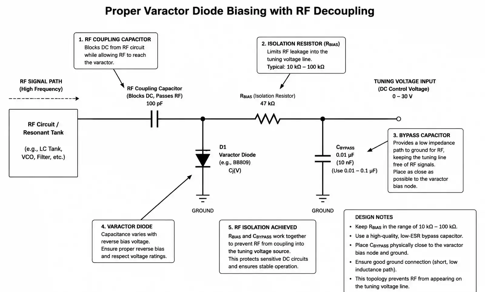
A common mistake in varactor diode applications is insufficient RF decoupling of the tuning voltage line. RF signals can couple onto the DC bias line, causing modulation of the tuning voltage and introducing unwanted frequency deviation or noise. Always include a series resistor (typically 10 kΩ to 100 kΩ) and bypass capacitor on the tuning voltage line, positioned as close as possible to the varactor cathode. The bypass capacitor must have sufficient RF impedance while maintaining low impedance at the tuning voltage frequency.
Temperature compensation requires careful attention in precision applications. Variable capacitors with positive temperature coefficients can compensate for inductors or other capacitors with negative temperature coefficients. When this technique is impractical, consider using temperature-compensated circuit designs or active temperature control. In critical applications, verify temperature stability through thermal testing across your full operating temperature range before committing to production.
Mechanical reliability issues arise when variable capacitors experience vibration or shock. Ensure mechanical mounting provides adequate support without inducing stress on the component body. Trimmer capacitors require thread-locking compounds on adjustment screws in vibration environments to prevent drift. Air-gap variable capacitors may need locking mechanisms to maintain position after adjustment. Test your design under anticipated mechanical stress conditions to verify stability.
Voltage breakdown in high-power RF applications often results from inadequate voltage rating selection or failure to account for voltage multiplication in resonant circuits. At resonance, voltage across the variable capacitor can significantly exceed the applied RF voltage. Calculate the circuit Q and multiply the RF voltage by the circuit Q to determine the actual voltage stress on the component. In high-power antenna tuners, voltage multipliers of 10× to 50× are common, requiring careful component selection and circuit design.
Parasitic effects become dominant at high frequencies. The series inductance of component leads and internal structure creates self-resonance typically between 500 MHz and 5 GHz depending on capacitor construction. Operating near or above self-resonance renders the component unusable. Minimize lead lengths, consider surface-mount trimmer capacitors for frequencies above 1 GHz, and verify self-resonant frequency specifications in datasheets. When self-resonance limits performance, consider MEMS variable capacitors or varactors specifically designed for high-frequency operation.
Adjustment range limitations often surprise designers unfamiliar with variable capacitor behavior in resonant circuits. The frequency tuning range is not linearly proportional to the capacitance range. For LC oscillators, frequency varies as 1/√C, meaning a 4:1 capacitance ratio provides only a 2:1 frequency range. Plan your tuning range carefully and consider whether a single variable capacitor can cover your required frequency span or whether band-switching with multiple fixed capacitors is necessary.
6. Supply Chain and Sourcing Considerations
Variable capacitor availability presents unique supply chain challenges compared to fixed capacitors. Many traditional manufacturers have discontinued older product lines, particularly mechanical variable capacitors, as demand shifted toward solid-state alternatives. This trend affects long-term product availability, making second-source identification critical during design phase. When specifying air-gap variable capacitors for new designs, verify current production status and projected long-term availability with manufacturers and authorized distributors.
Lead times for specialized variable capacitors, particularly high-voltage air-gap types and precision glass trimmers, often extend from 12 to 26 weeks. Standard ceramic trimmers and common varactor diodes maintain shorter lead times of 4 to 8 weeks, though market conditions can affect availability. For production planning, identify critical components early in the design cycle and communicate forecast requirements to suppliers to secure capacity allocation.
Cost considerations vary dramatically across variable capacitor types. Standard ceramic trimmers range from $0.50 to $3.00 in production quantities, while precision glass and air trimmers cost $5.00 to $30.00. High-voltage air-gap variable capacitors for RF power applications can exceed $50.00 to $200.00 per unit. Varactor diodes typically cost $0.25 to $2.00 depending on specifications, making them cost-competitive with mechanical alternatives when electronic tuning suits the application. MEMS variable capacitors currently command premium pricing, though costs decrease as production volumes increase.
Obsolescence risk requires proactive management. Several major manufacturers have exited the mechanical variable capacitor market or significantly reduced product offerings. Document critical specifications for all variable capacitors in your design, including mechanical dimensions, electrical parameters, and mounting details. When designing long-lifecycle products (10+ years), consider allocating budget for lifetime buys or maintaining qualification of multiple sources. Alternative approaches include designing tuning circuits that accommodate parameter variations across different variable capacitor models, reducing dependency on single-source components.
Counterfeit components pose risks, particularly for older variable capacitor designs where original manufacturers no longer exist. Source components exclusively from authorized distributors and manufacturers' direct channels. Request certificates of conformance and consider implementing incoming inspection for critical parameters like capacitance range and Q factor. For high-reliability applications in aerospace or medical devices, specify components with full traceability and quality certifications.
7. FAQ
What is the difference between a trimmer capacitor and a variable capacitor?
Trimmer capacitors are designed for infrequent adjustment during calibration or tuning, typically accessed only during manufacturing or service. They feature compact size, sealed construction, and screw-adjustable mechanisms. Variable capacitors support frequent user adjustment with accessible controls like shafts or knobs, common in radio tuning applications. While both offer capacitance adjustment, the distinction lies in adjustment frequency, access method, and mechanical durability requirements.
How do I calculate the capacitance range needed for my RF oscillator?
Use the oscillator frequency equation f = 1/(2π√LC) at both frequency extremes. First, calculate the total capacitance needed at the minimum frequency: C_total_min = 1/(4π²f_min²L). Then calculate for maximum frequency: C_total_max = 1/(4π²f_max²L). Account for all circuit capacitances (PCB parasitic, transistor input capacitance, fixed capacitors) by subtracting them from the total. The remaining capacitance range determines your variable capacitor requirements with a 10-20% margin for adjustment flexibility.
Can varactor diodes replace mechanical variable capacitors in all applications?
Varactor diodes excel in applications requiring electronic control, fast tuning, and remote adjustment, but present limitations compared to mechanical variable capacitors. They offer lower Q factors (typically 100-500 vs 1000-2000), introduce non-linear tuning characteristics requiring compensation, and exhibit temperature sensitivity. High-power RF applications exceeding 10W often require mechanical variable capacitors due to voltage handling limitations of varactors. Evaluate Q factor requirements, linearity needs, power levels, and control interface preferences when considering varactor alternatives.
What causes frequency drift in variable capacitor circuits?
Multiple factors contribute to frequency drift. Temperature changes affect both the variable capacitor (via temperature coefficient) and associated components like inductors. Mechanical vibration can alter plate spacing in air-gap capacitors or shift adjustment positions. Humidity affects dielectric properties in non-sealed components. Component aging particularly affects varactor diodes and some dielectric materials. Poor contact resistance in mechanical connections introduces resistance drift. Mitigate drift through temperature compensation design, sealed component selection, mechanical stabilization, and proper PCB layout practices.
How do I prevent RF coupling into varactor tuning voltage lines?
Implement a series resistor (10 kΩ to 100 kΩ) immediately adjacent to the varactor cathode to isolate the tuning voltage source from RF signals. Add a bypass capacitor (typically 0.01 µF to 0.1 µF) from the tuning voltage node to ground, positioned close to the varactor. For sensitive applications, use multiple stages of RC filtering. Keep tuning voltage traces short and route them away from high-RF-current paths. Consider using differential tuning or balanced configurations to minimize common-mode RF pickup.
What testing should I perform to validate variable capacitor selection?
Measure capacitance range across the full adjustment range using an LCR meter at your operating frequency. Verify Q factor at critical frequencies, as datasheet values may not reflect your specific circuit conditions. Test voltage rating under actual RF power conditions, not just DC voltage. Perform temperature cycling across your operating range while monitoring frequency stability. Subject mechanical types to vibration testing to verify adjustment stability. For varactors, characterize the C-V curve and verify tuning linearity meets requirements. Test for spurious resonances and parametric oscillations in the final circuit configuration.
Are there pin-compatible alternatives if my variable capacitor becomes obsolete?
Pin compatibility is rare in variable capacitors due to varied mechanical designs and mounting styles. Instead, design tuning circuits with parameter tolerance to accommodate different variable capacitor models. Document equivalent specifications (capacitance range, Q factor, voltage rating, mounting dimensions) rather than specific part numbers. Maintain relationships with multiple suppliers offering similar specifications. For critical long-lifecycle products, consider lifetime buys or maintain qualification of alternative components before obsolescence occurs. Digital tuning using switched capacitor arrays provides another alternative offering improved long-term availability.
What is the typical lifespan of different variable capacitor types?
Air-gap variable capacitors designed for frequent adjustment typically endure 10,000 to 50,000 adjustment cycles before mechanical wear affects performance. Trimmer capacitors, intended for infrequent adjustment, survive 100 to 500 cycles. Varactor diodes have no moving parts but experience parametric drift over time, particularly at elevated temperatures; typical reliable lifespans exceed 20 years under normal operating conditions. MEMS devices typically withstand millions of switching cycles but remain sensitive to electrostatic discharge and mechanical shock. Environmental factors including temperature cycling, vibration, humidity, and contamination significantly affect lifespan across all types.
8. Conclusion
Variable capacitor selection demands careful evaluation of electrical parameters, mechanical requirements, environmental conditions, and supply chain factors. Air-gap variable capacitors remain the preferred choice for high-Q RF applications and high-power tuning despite larger size. Trimmer capacitors excel in set-and-forget calibration scenarios where stability and resolution matter most. Varactor diodes enable electronic tuning essential for modern communications systems, accepting Q factor and linearity trade-offs. MEMS technology pushes performance boundaries in size-constrained applications willing to accept premium pricing.
For RF tuning applications prioritizing Q factor and power handling, specify air-gap variable capacitors with appropriate voltage ratings and capacitance ranges. When designing VCOs or frequency synthesizers requiring electronic control, varactor diodes provide the necessary tuning speed and remote adjustment capabilities. Calibration and fine-tuning applications benefit from multi-turn trimmer capacitors offering superior resolution and mechanical stability.