



Vishay VS-36MT100 Three-Phase Bridge Rectifier Selection Guide: Real-World Design Considerations
The Vishay VS-36MT100 is a 35 A, 1000 V three-phase bridge rectifier in a D-63 package suitable for industrial power conversion, motor drives, and instrumentation. The 35 A rating applies at TC=60°C with 120° conduction—not an unconditional limit—so thermal design determines whether it fits your application. This guide covers specification interpretation, thermal calculation, application selection, and design checks that prevent field failures.
Table of Contents
- VS-36MT100 Core Specifications and Rating Interpretation
- Three-Phase Bridge Circuit Configuration
- Thermal Design: Converting Ratings to Real Heat Sinks
- Application Selection: Where the VS-36MT100 Fits
- D-63 Package Mounting and Terminal Connections
- Common Design Mistakes and Field Failure Modes
- VS-36MT100 Alternatives and Upgrade Paths
- Troubleshooting Three-Phase Rectifier Failures
- FAQ
- Conclusion
VS-36MT100 Core Specifications and Rating Interpretation
The VS-36MT100 belongs to Vishay's VS-36MT series, where "36" indicates the 35 A current rating code and "100" represents the 1000 V voltage code (code × 10 = VRRM).
| Parameter | VS-36MT100 Value | Critical Condition |
|---|---|---|
| Maximum DC output current (IO) | 35 A | TC=60°C, 120° conduction |
| Repetitive peak reverse voltage (VRRM) | 1000 V | Per diode junction |
| Forward voltage drop (VFM) | 1.19 V | Per junction at IFM=40 A, TJ=25°C |
| One-cycle surge current (IFSM) | 475 A @ 50 Hz | No reverse voltage reapplied |
| Junction-to-case thermal resistance (RθJC) | 1.35 K/W | Per bridge, DC operation |
| Case-to-sink thermal resistance (RθCS) | 0.2 K/W | Flat greased surface |
| Operating junction temperature (TJ) | -55°C to +150°C | Absolute maximum |
The 35 A rating assumes 60°C case temperature and 120° rectangular conduction. Real-world conduction angle depends on source impedance and DC-link capacitance—higher capacitance increases RMS current through each diode pair, raising losses.
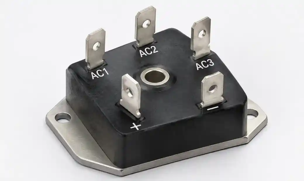 VS-36MT100 three-phase bridge rectifier showing D-63 package with terminals and mounting hole
The 1.19 V forward drop translates to roughly 1.0 V at 35 A average. Two diodes conduct at any instant, so expect 2.0 V total drop. At 35 A output, that's approximately 70 W bridge dissipation—thermal design starts here.
Three-Phase Bridge Circuit Configuration
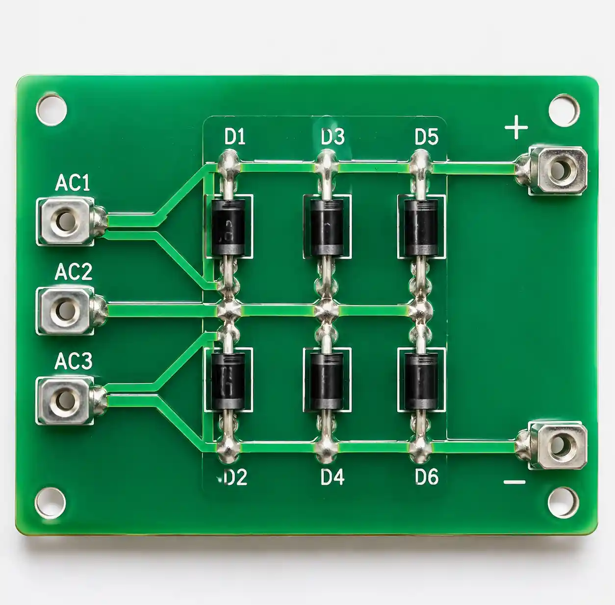 Three-phase bridge rectifier circuit diagram showing six-diode configuration and current flow
The VS-36MT100 contains six diodes arranged as a three-phase full-wave bridge. Three AC terminals (AC1, AC2, AC3) connect to the three-phase supply; two DC terminals (+, −) deliver rectified output. During each 60° segment, one diode connects the highest-voltage phase to positive while another connects negative to the lowest-voltage phase.
This six-pulse rectification produces DC output with approximately 4% RMS ripple at no load. Source inductance causes commutation overlap—during which three diodes conduct simultaneously—increasing average diode current and slightly reducing output voltage by 2–3% from ideal.
In motor drives, the bridge feeds a DC link with capacitance, then an inverter reconstructs AC at variable frequency. The rectifier experiences inrush current during startup as the DC-link capacitor charges. The 475 A one-cycle surge rating handles typical inrush, but soft-start circuits prevent repeated stress.
Thermal Design: Converting Ratings to Real Heat Sinks
Thermal design determines whether the VS-36MT100 survives. The 35 A rating means junction temperature reaches maximum (150°C) when case temperature is 60°C, given RθJC of 1.35 K/W.
Calculating required heat sink:
- Estimate bridge dissipation: P = 2 × VFM × IO. At 35 A with 1.0 V per diode: P ≈ 70 W.
- Define maximum ambient: TA = 50°C for industrial equipment.
- Set junction target: TJ = 125°C (25°C margin below maximum).
- Calculate total thermal resistance: RθJA = (TJ − TA) / P = (125 − 50) / 70 = 1.07 K/W.
- Subtract junction-to-case and case-to-sink: RθSA = 1.07 − 1.35 − 0.2 = −0.48 K/W.
This negative result means 35 A is not achievable at 50°C ambient with passive cooling. At 20 A: P ≈ 40 W, RθSA = 0.52 K/W—achievable with a decent heat sink.
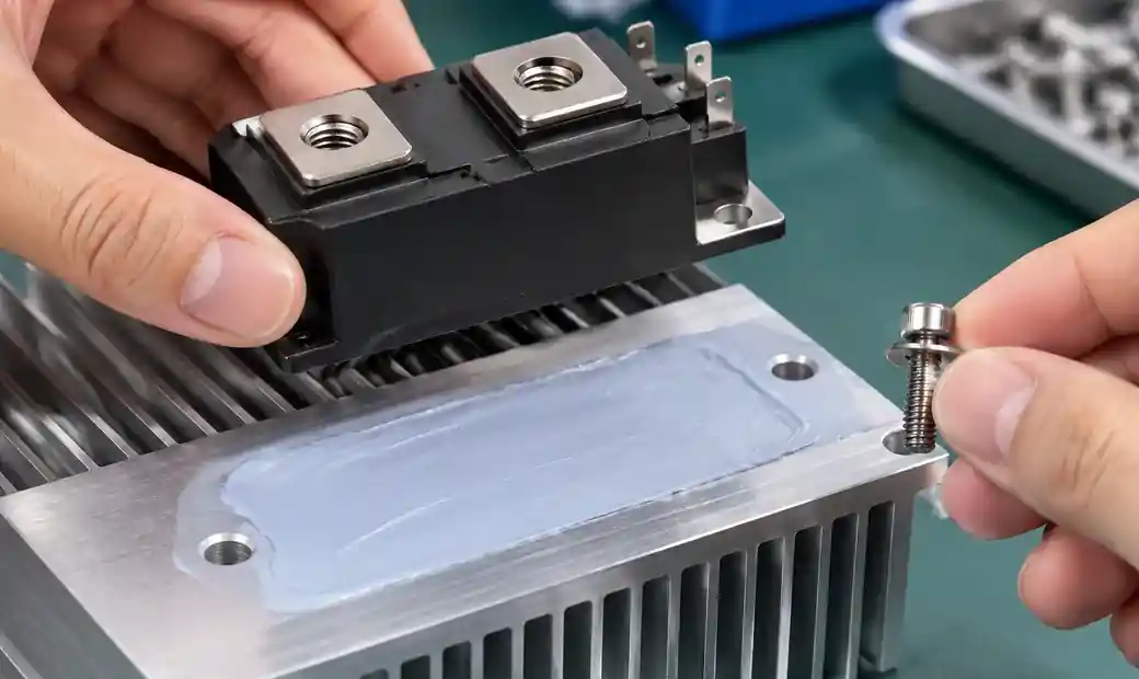 Heat sink with thermal compound application for power rectifier mounting
Practical thermal considerations:
- The 0.2 K/W case-to-sink resistance assumes flat, smooth, greased surface with 2.0 N·m torque. Warped heat sinks can double this resistance.
- Forced airflow dramatically improves performance. A 40 mm fan can reduce effective RθSA by 50–70%.
- Design for end-of-life conditions with dust accumulation, not clean-room testing.
Application Selection: Where the VS-36MT100 Fits
| Application | Current Range | Voltage Need | VS-36MT100 Fit | Notes |
|---|---|---|---|---|
| 480 VAC industrial power supplies | 15–25 A | 1000 V+ | Excellent | Voltage margin for transients |
| 400 VAC motor drive front-end | 20–30 A | 800 V+ | Good | Forced-air cooling needed |
| Three-phase battery chargers | 10–20 A | 600–1000 V | Excellent | Soft-start required |
| 208 VAC commercial equipment | 25–35 A | 600 V+ | Over-spec voltage | Consider lower-voltage option |
The VS-36MT100 excels in 480 VAC industrial systems where 1000 V rating provides transient margin. In motor drives, size heat sink for 80–90% of rated current for reliability. Add pre-charge resistor to limit DC-link capacitor inrush.
D-63 Package Mounting and Terminal Connections
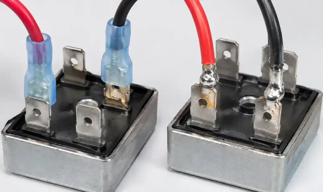 D-63 package terminal connections showing push-on connectors and solder joints
The D-63 package measures 28.5 × 24 mm with a central 5.2 mm mounting hole. The electrically isolated case means the mounting screw connects directly to grounded heat sink without insulating washers—simplifying assembly and improving thermal transfer.
Terminal connection options:
- Push-on connectors: 6.3 mm blade terminals. Use insulated connectors rated for 50 A minimum.
- Solder connections: Use high-temperature solder (melting point >220°C) to prevent reflow during operation.
Mounting procedure:
- Clean heat-sink surface with isopropyl alcohol.
- Apply thin thermal compound layer (silicone-based grease).
- Position rectifier with correct AC terminal orientation.
- Install M4 screw with flat washer; tighten to 2.0 N·m ±10%.
- Verify thermal contact—case temperature under load should match calculated value within 10°C.
Common Design Mistakes and Field Failure Modes
After reviewing dozens of three-phase rectifier failures in industrial drives, these patterns emerge:
Insufficient heat-sink margin: Designers calculate at maximum ambient but forget dust accumulation and aging thermal compound. Field failures occur after 2–3 years. Solution: Design for 20% thermal margin and specify periodic maintenance.
Ignoring inrush current: DC-link capacitors draw massive inrush on startup, sometimes exceeding 475 A during repeated power cycling. Solution: Add NTC thermistor or pre-charge circuit limiting inrush to <300 A.
Inadequate voltage margin: The 1000 V rating provides minimal margin for 480 VAC systems (peak = 679 V). Lightning or utility switching can spike to 1200–1500 V. Solution: Add MOVs across AC inputs.
Mismatched DC-link capacitance: Excessive capacitance increases diode RMS current; insufficient allows ripple into the load. Solution: Calculate ripple current and verify diode RMS rating.
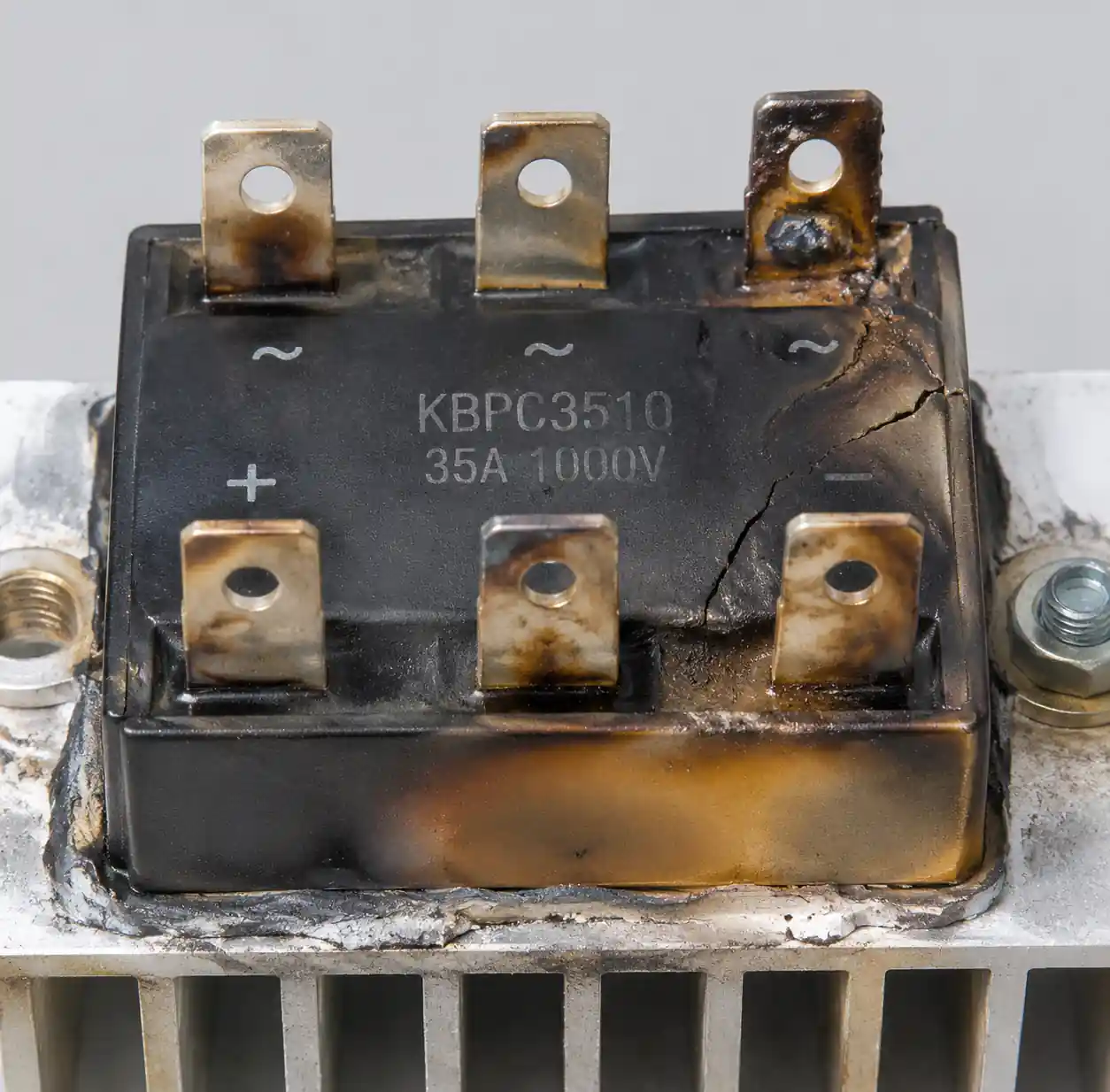 Failed three-phase bridge rectifier showing thermal damage and burnt components
VS-36MT100 Alternatives and Upgrade Paths
When the VS-36MT100 doesn't fit, consider these alternatives:
| Part Number | Current | Voltage | Manufacturer | Key Difference |
|---|---|---|---|---|
| VS-36MT120 | 35 A | 1200 V | Vishay | Higher voltage for 600 VAC |
| VS-36MT160 | 35 A | 1600 V | Vishay | Maximum transient protection |
| DB35-10 | 35 A @ 55°C | 1000 V | Diotec | Different package—verify dimensions |
Before substituting, verify terminal layout, thermal resistance ratings, surge current specifications, and package dimensions. For higher current needs, the VS-56MT100 (55 A) uses a larger package.
Troubleshooting Three-Phase Rectifier Failures
| Symptom | Likely Cause | Check | Solution |
|---|---|---|---|
| No DC output | Open diode or connection | Measure AC input; test diodes with power off | Replace rectifier; check upstream fuse |
| Low DC voltage | Missing phase or weak AC | Check all three phases; measure unloaded DC | Verify source; check connections |
| Excessive ripple | Failed diode or low capacitance | Scope DC output; compare to expected ripple | Replace if diode open; increase capacitance |
| Overheating | Undersized heat sink | Measure case temperature; compare to calculation | Improve cooling or reduce load |
| Repeated fuse trips | Shorted diode or load fault | Disconnect load; test diodes | Replace rectifier; investigate load |
When a diode fails short, the fuse clears before other damage. When a diode opens, output drops roughly 15% and ripple increases. To test with power removed, use multimeter diode mode: each AC terminal should show 0.6–0.7 V drop to + (forward bias) and open circuit when reversed.
 Digital multimeter in diode test mode measuring bridge rectifier terminals
FAQ
Q: Can I parallel two VS-36MT100 modules for higher current?
Paralleling is possible but requires matched forward voltage and shared thermal design. Forward voltage varies ±10% between units, causing unequal current sharing. If necessary, use inductors in series with each AC input to balance current, and ensure both modules share the same heat sink.
Q: What's the actual maximum current I can safely run?
It depends on case temperature, which depends on heat sink and ambient. The 35 A rating assumes TC=60°C. If case stays at 50°C, you can push to 40 A. If ambient is 60°C with minimal cooling, expect 15–20 A maximum.
Q: Do I need AC-side fuse or just DC-side protection?
Both. AC-side fuses protect the rectifier from upstream faults. DC-side fuses protect downstream circuits from rectifier failures. Use fast-acting fuses on AC side rated for three-phase service.
Q: How do I add transient protection without excessive capacitance?
Use MOVs or TVS diodes across each AC input phase-to-ground and phase-to-phase. These clamp transients above 1200 V without increasing DC-link capacitance. Add small film capacitors (0.1–1 μF) for high-frequency noise.
Conclusion
The VS-36MT100 provides reliable three-phase rectification when properly specified and thermally managed. The 35 A rating applies under specific thermal conditions—calculate dissipation and heat-sink requirements before committing to the design. The 1000 V rating suits 480 VAC industrial systems with transient protection, but consider higher-voltage variants for 600 VAC or lightning-prone installations.
Success depends on three factors: accurate thermal calculation during design, proper mounting with specified torque and thermal interface, and adequate inrush current limiting during startup. Field failures typically trace to insufficient cooling margin, repeated surge stress, or voltage transients beyond the 1000 V rating. Design for end-of-life conditions, not clean benchtop testing, and include periodic maintenance for dust removal and thermal compound refresh.