



Optocoupler vs Solid State Relay: Which One Your Circuit Actually Needs
After designing industrial control systems for over a decade, I've watched engineers waste weeks debugging circuits because they confused signal isolation with power switching. Here's the reality: optocouplers transfer control signals across isolation barriers, while solid state relays switch actual loads. The choice depends on whether you're passing information or switching power. This guide breaks down the functional differences, shows real-world selection criteria based on voltage, current, switching behavior, and thermal limits, and reveals the costly mistakes I've seen repeated in production designs.
Table of Contents
The Core Functional Difference Nobody Explains Clearly
The industry has created confusion by treating these as interchangeable "isolation devices." They're not. In real circuits, an optocoupler moves a logic signal, feedback voltage, or gate-drive pulse from one ground reference to another. You then use that signal to drive something else—a microcontroller input, a MOSFET gate, or a transistor base.
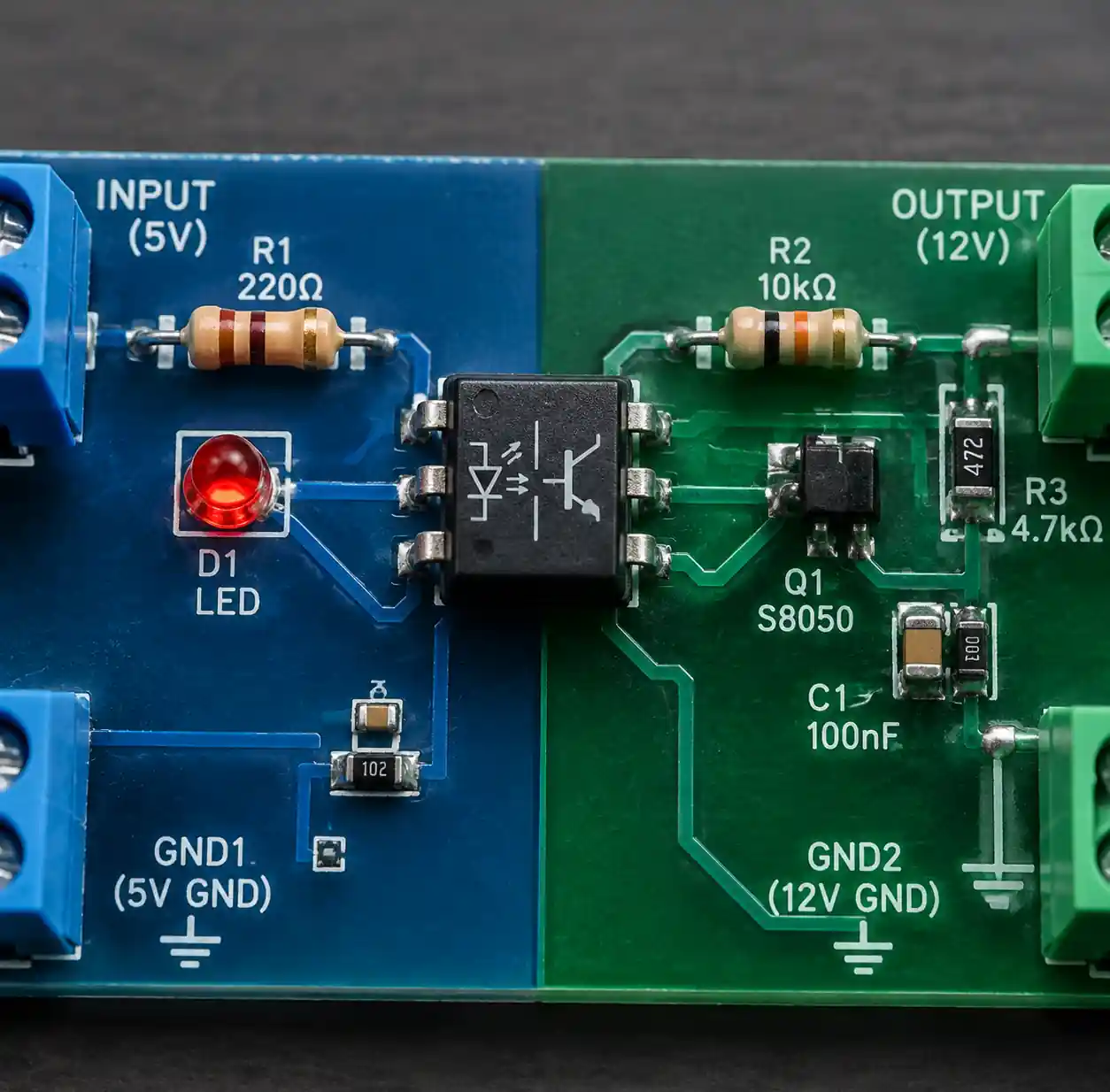 Optocoupler transferring control signal between two isolated circuits
An SSR contains a complete switching stage designed to carry your load current directly. When you energize the SSR input, its internal TRIAC, SCR, or MOSFET conducts load current through the output terminals. The isolation happens internally, but the device itself closes the load circuit.
This distinction matters because it determines everything: current rating, thermal design, turn-off behavior, and whether your load will actually work. I've seen motors refuse to start because an engineer used a signal optocoupler where the circuit needed an SSR's power-switching capability.
When Real Circuits Demand Each Device
Optocoupler Territory
Optocouplers dominate feedback paths in isolated power supplies. The output voltage gets sampled, converted to an LED current, and the isolated phototransistor or photodiode delivers that signal to the primary-side controller. CTR variation matters here—if your minimum CTR drops below design margins across temperature and aging, regulation suffers.
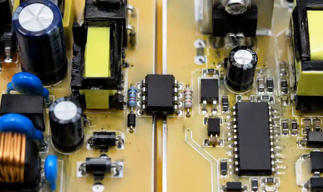 Power supply feedback circuit using optocoupler for voltage regulation
They're also essential for PLC digital inputs, where external sensors send 24VDC signals that need isolation before reaching 3.3V or 5V logic. You'll specify input current (typically 5–10mA), isolation voltage (often 2500Vrms for industrial), and propagation delay if you're catching fast pulses.
Zero-cross detection circuits use optocouplers with AC-rated LEDs to trigger at voltage crossings, feeding timing signals to controllers for TRIAC firing or synchronization. The optocoupler sees the AC waveform through a resistor network but only signals the event—it doesn't switch the load.
SSR Applications Where They Excel
AC heaters and industrial heating elements are classic SSR loads. A microcontroller or PID controller sends 3–32VDC to the SSR input, and the TRIAC output switches 240VAC at 25A or more. The key parameters: load current with proper derating, surge current for turn-on inrush, and mounting the SSR to an adequate heat sink because that 1.6V forward drop at 25A dissipates 40W.
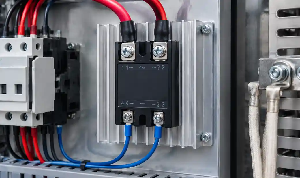 Solid state relay mounted on heat sink switching industrial heater load
Motor contactors and solenoid valves get switched by SSRs in automated systems. For three-phase motors, you'll use three SSRs (one per phase) or a mechanical contactor—the SSR energizes the contactor coil to avoid switching the motor current directly unless the SSR is specifically rated for motor inrush.
DC loads like LED lighting, actuators, and electronic heaters use MOSFET-output SSRs. These have low on-resistance (often 0.05–0.2Ω), so conduction loss becomes I²R rather than a fixed voltage drop. The advantage: better efficiency at higher currents, but you must verify the maximum junction temperature isn't exceeded during continuous operation.
Comparison Table: Electrical Characteristics
| Parameter | Signal Optocoupler | Solid State Relay |
|---|---|---|
| Output current | 50mA–150mA (phototransistor), varies by type | 2A–100A+ depending on model |
| Voltage drop | Vce(sat) ~0.2–0.4V (phototransistor) | 1.2–1.6V (TRIAC/SCR), I²R (MOSFET) |
| Off-state leakage | nA–µA range, typically negligible | mA range, can partially energize sensitive loads |
| Switching speed | 3–500µs depending on output type | Zero-cross: half-cycle delay; random: µs–ms |
| Thermal dissipation | Minimal (<0.1W typical) | Significant (calculate Von×I or I²Ron) |
| Isolation voltage | 2.5kV–5kV typical test voltage | 2kV–6kV typical test voltage |
| Primary use | Signal transfer, feedback, gate drive | Direct load switching |
Comparison Table: Application Selection Criteria
| Selection Factor | Choose Optocoupler When... | Choose SSR When... |
|---|---|---|
| Function | Transferring signals between circuits | Switching power to a load |
| Current | Output drives logic, gates, or small transistors | Device must carry the full load current |
| Load type | N/A—output feeds control circuitry | AC resistive, inductive; DC with proper type |
| Switching behavior | Need fast propagation or analog coupling | Need zero-cross (AC) or clean DC switching |
| Off-state requirement | Near-zero leakage critical | Some leakage acceptable |
| Thermal management | Minimal heat generation | Heat sinking required for most loads |
| Cost sensitivity | Low-cost signal isolation | Higher cost justified by switching capability |
The Selection Process Based on Real Design Constraints
Step 1: Define the Actual Function
Ask: does this device need to carry the load current, or does it pass a signal that controls something else? If you're switching a 10A heater, you need an SSR. If you're sending a logic pulse to a microcontroller across isolation, you need an optocoupler.
Step 2: Check Load Current and Voltage
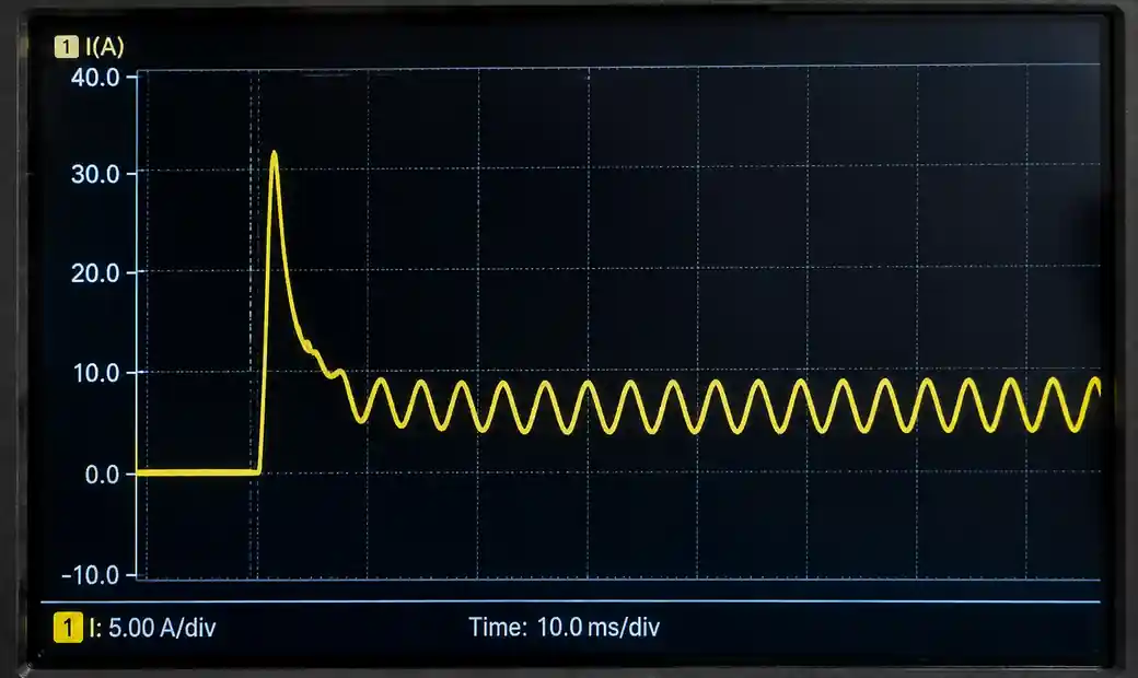 Oscilloscope capture showing load inrush current surge during SSR turn-on
For SSRs, calculate peak current including inrush. Incandescent lamps surge 10–15× their steady-state current; capacitive loads cause current spikes at turn-on. Your SSR must handle the worst-case surge without exceeding the non-repetitive peak-current rating, and the continuous current must include thermal derating at your ambient temperature.
Optocouplers specify maximum collector or output current, but that's for the transistor itself—your external circuit must limit current through the optocoupler output.
Step 3: Match AC or DC and Output Technology
TRIAC-based SSRs work for AC loads because the TRIAC naturally turns off at current zero-crossing. If you try to switch DC with a TRIAC SSR, the TRIAC latches on and won't turn off—it needs the current to drop below holding current, which doesn't happen in DC circuits.
MOSFET SSRs switch DC loads cleanly and can also switch AC if configured as back-to-back MOSFETs. The on-resistance is bidirectional, and the control circuit handles turn-off actively.
Step 4: Verify Switching Behavior for the Load
Zero-cross SSRs reduce EMI and inrush for resistive heaters and incandescent lamps by waiting for near-zero voltage before turning on. But zero-cross switching delays turn-on by up to half an AC cycle, which breaks phase-angle control or causes issues with transformer-coupled loads that need energization at a specific phase.
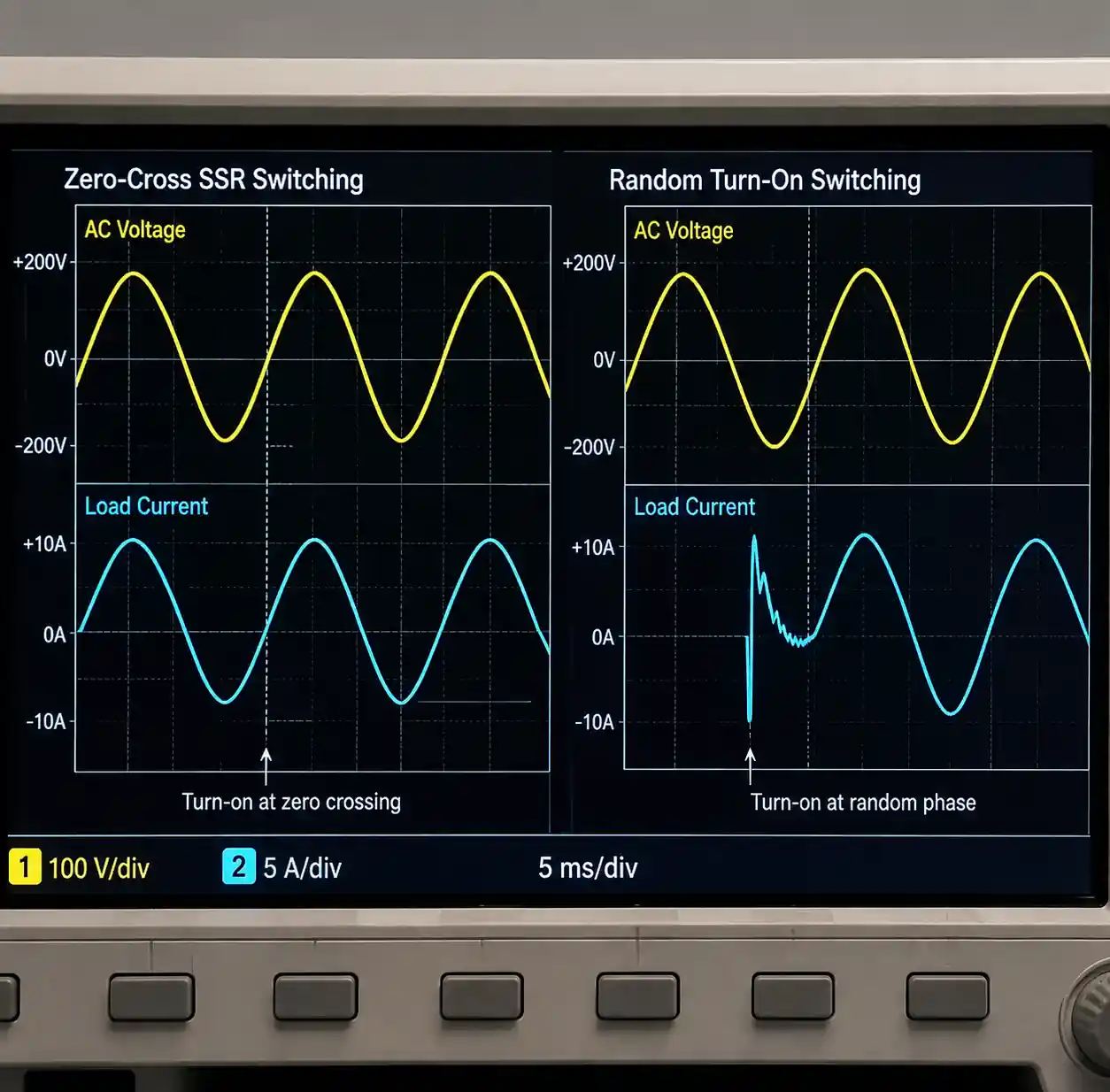 Comparison of zero-cross and random turn-on SSR switching behavior on scope
Random-turn-on SSRs switch immediately but generate switching transients. They're necessary for phase control but require snubbers or additional filtering in noise-sensitive systems.
Step 5: Calculate Thermal Dissipation and Heat Sinking
Use the manufacturer's derating curves, not just the headline current rating. A 25A SSR might only handle 10A at 60°C ambient without a heat sink. For TRIAC SSRs, estimate power as Von × I (e.g., 1.5V × 20A = 30W). For MOSFET SSRs, use I² × Ron (e.g., 15A² × 0.1Ω = 22.5W).
Check the thermal resistance from junction to case (Rθ(j-c)) and case to heat sink (Rθ(c-s)), then calculate junction temperature:
Tj = Ta + P × (Rθ(j-c) + Rθ(c-s) + Rθ(s-a))
If Tj exceeds the maximum rating (typically 125°C), you need a larger heat sink or a higher-rated SSR.
Step 6: Address Off-State Leakage
SSR leakage current (often 1–5mA) can cause problems. LED loads may glow faintly when the SSR is off, electronic ballasts may not fully shut down, and low-power control circuits may not drop out. If your load can't tolerate leakage, add a bleed resistor across the load or reconsider the SSR choice.
Optocouplers have negligible leakage in comparison, making them suitable for circuits where even microamps of off-state current cause issues.
Critical Design Mistakes I've Debugged in Production
Underestimating Inrush Current
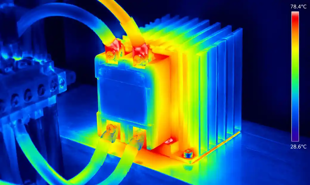 Thermal camera image showing heat distribution in SSR under load current
A client used a 16A SSR for a 10A heater—seemed safe until the heater's cold-resistance inrush hit 35A for three cycles and destroyed the SSR. Always check the I²t rating and non-repetitive surge current, and consider a soft-start circuit or higher-rated SSR for inrush-heavy loads.
Ignoring Inductive Transients
Switching inductive DC loads without suppression generates voltage spikes that exceed the SSR's breakdown voltage. For DC inductive loads, add a flyback diode or TVS clamp rated for the energy stored in the inductor (½LI²). For AC inductive loads (motors, transformers), use an RC snubber across the SSR output or a MOV varistor—consult the SSR datasheet for recommended values.
Confusing Isolation Test Voltage with Working Voltage
The 4000Vrms isolation rating on an optocoupler datasheet is a one-minute dielectric test, not a continuous working voltage. The actual repetitive peak isolation voltage or continuous working voltage is much lower and appears separately in safety documentation. Applying continuous voltage near the test voltage will cause insulation breakdown over time.
Using Optocouplers for Direct Load Switching
I've seen engineers try to switch a relay coil or small solenoid directly with an optocoupler output, assuming the 50mA collector current is sufficient. It might work initially, but the optocoupler overheats, CTR degrades, and the circuit fails intermittently. If you're switching a load, use an SSR or add a discrete transistor stage after the optocoupler.
FAQ
Can I use an optocoupler to switch a small heater or relay directly?
Not reliably. Optocoupler outputs are designed for signal-level currents or driving external transistors. For direct switching, use an SSR or add a MOSFET/bipolar transistor driven by the optocoupler.
Why does my SSR get hot even at half its rated current?
SSR current ratings assume a specific heat sink and ambient temperature. Check the derating curve—most SSRs require significant heat sinking above 10A. Also calculate actual power dissipation using the on-state voltage drop or resistance.
Can I switch DC loads with an AC-rated SSR?
No. TRIAC- or SCR-based AC SSRs won't turn off properly with DC current because there's no zero crossing. Use a DC-rated MOSFET SSR for DC loads.
What causes LED flicker or glow when the SSR is off?
SSR off-state leakage current (typically 1–5mA) can partially energize LEDs or electronic ballasts. Add a bleed resistor (e.g., 100kΩ for 240VAC) across the load to shunt leakage current.
How do I choose between zero-cross and random turn-on for an AC SSR?
Use zero-cross for resistive heating, lighting, and most ON/OFF control—it reduces inrush and EMI. Use random turn-on for phase-angle control, dimming, or when you need immediate turn-on within the AC cycle.
Do I need snubbers or protection circuits for SSRs?
For AC inductive loads, yes—an RC snubber or MOV varistor protects the SSR from voltage transients. For DC inductive loads, use a flyback diode or TVS clamp. Check the SSR manufacturer's recommendations for component values.
Conclusion
Choosing between optocouplers and SSRs comes down to a single question: are you transferring a signal or switching a load? Optocouplers excel at isolated signal paths—feedback loops, digital inputs, gate drives—where the output feeds control circuitry. SSRs directly switch power to heaters, motors, and solenoids, with thermal management and surge ratings as critical design parameters.
The real-world selection process requires checking load current including inrush, verifying AC/DC compatibility, calculating power dissipation with proper derating, and confirming that off-state leakage won't affect your load. Engineers who skip thermal calculations or ignore inductive transients end up with failed SSRs in production. Those who use optocouplers for direct switching face overheating and reliability issues. Match the device to the function, verify every electrical limit in the datasheet, and design the thermal and protection circuits the manufacturer specifies. That's how you avoid the rework and field failures I've seen repeated across industries.