


40 Amp Wire Size: Complete Selection Guide for Electrical Installations
Selecting the correct wire size for a 40-amp circuit is critical for electrical safety, code compliance, and system performance. An undersized conductor can lead to voltage drop, overheating, and fire hazards, while oversizing increases material costs unnecessarily. This guide explains how to choose the right wire gauge for 40-amp applications based on conductor material, installation method, ambient temperature, and distance.
Table of Contents
- What Determines Wire Size for 40 Amp Circuits
- Wire Gauge Requirements by Material and Installation Method
- Key Factors Affecting Wire Size Selection
- Voltage Drop Considerations for Long Wire Runs
- Installation Best Practices and Code Compliance
- Common Mistakes and How to Avoid Them
- FAQ
- Conclusion
1. What Determines Wire Size for 40 Amp Circuits
Wire ampacity—the maximum current a conductor can safely carry—depends on multiple variables beyond just the breaker rating. For a 40-amp circuit, the National Electrical Code (NEC) requires conductors rated for at least 125% of the continuous load, meaning you're actually designing for 50 amps in many continuous-duty applications. The primary determinant is the conductor's ability to dissipate heat without exceeding temperature ratings that could degrade insulation or create fire risk.
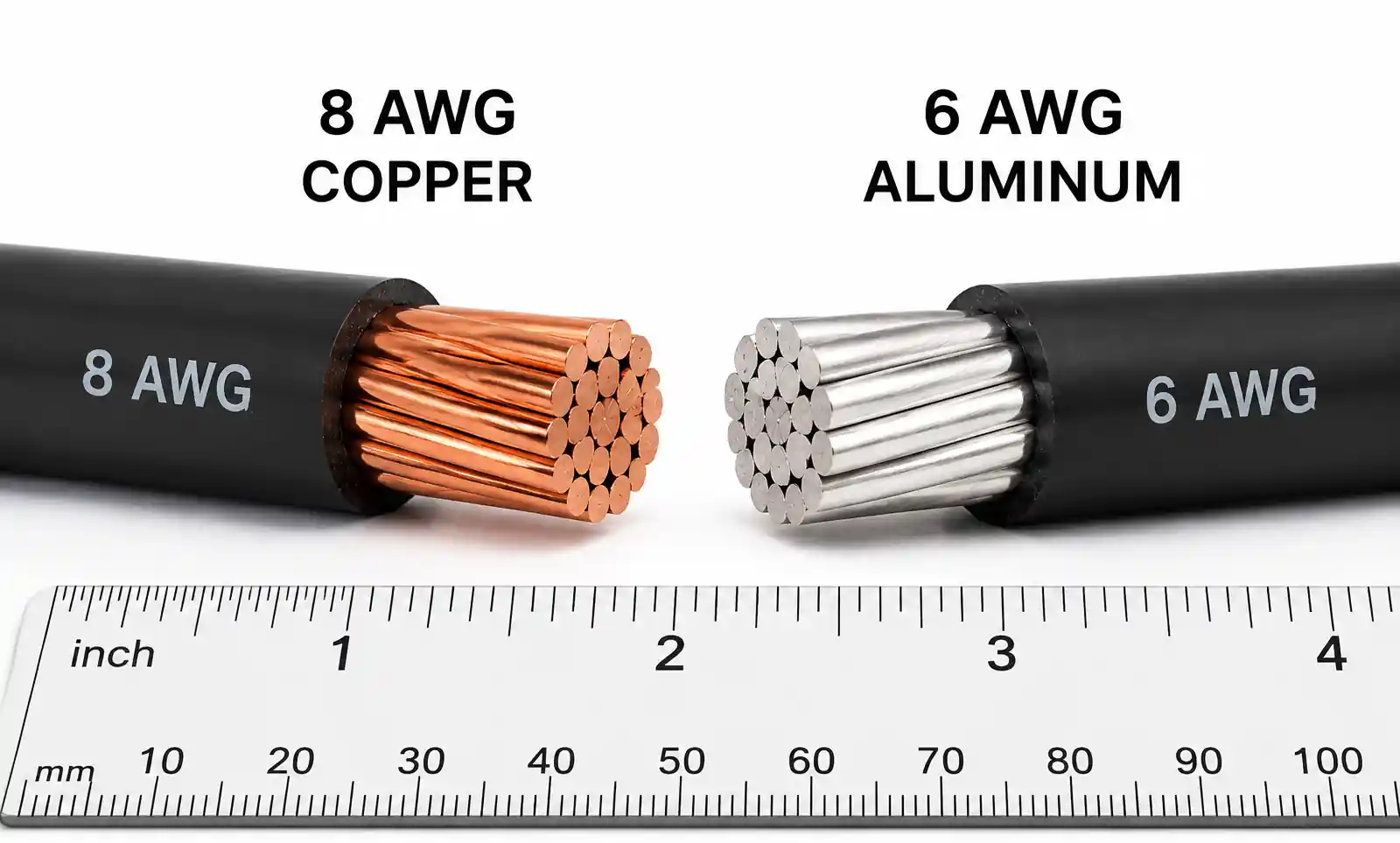
Copper and aluminum are the two standard conductor materials, with copper offering superior conductivity and requiring smaller wire gauges for the same ampacity. A 40-amp copper circuit typically requires 8 AWG wire in most residential and light commercial installations, while aluminum requires 6 AWG to carry the same current safely. However, these baseline values shift significantly based on installation environment and wire bundling.
The 75°C temperature rating applies to most residential wiring, but terminations at breakers and devices often limit you to 60°C ratings unless specifically marked otherwise. This temperature derating is one of the most overlooked factors in wire sizing. Additionally, the number of current-carrying conductors in a raceway, conduit temperature rise, and ambient conditions above 30°C all trigger NEC adjustment factors that may require upsizing from the baseline gauge.
2. Wire Gauge Requirements by Material and Installation Method
The table below shows minimum wire sizes for 40-amp circuits under standard conditions (75°C conductor rating, 30°C ambient, not more than three current-carrying conductors in a raceway). These values comply with NEC Table 310.16 and assume breaker terminals are rated for 75°C.
| Conductor Material | Wire Gauge (AWG) | Ampacity at 75°C | Ampacity at 60°C | Typical Application |
|---|---|---|---|---|
| Copper | 8 AWG | 50A | 40A | Range circuits, EV chargers, subpanels |
| Aluminum or Copper-Clad Aluminum | 6 AWG | 50A | 40A | Service entrance, feeder runs, long distances |
| Copper (conduit with >3 conductors) | 6 AWG | 55A (before derating) | N/A | Commercial installations with bundled circuits |
| Aluminum (conduit with >3 conductors) | 4 AWG | 65A (before derating) | N/A | Industrial feeders, long underground runs |
When more than three current-carrying conductors share a raceway, apply NEC adjustment factors: 80% for 4-6 conductors, 70% for 7-9 conductors, and 50% for 10-20 conductors. For example, if you have six 40-amp circuits in a single conduit, each copper conductor must be sized as if carrying 50A ÷ 0.8 = 62.5A, which requires upsizing from 8 AWG to 6 AWG copper.
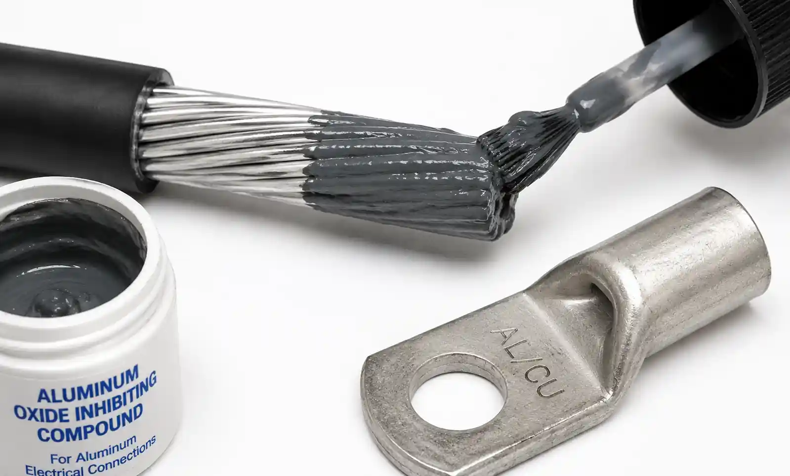
Aluminum conductors require special attention to termination methods. Aluminum oxidizes when exposed to air, creating a high-resistance layer at connection points. Always use antioxidant compound, torque connections to manufacturer specifications, and verify that terminals are rated AL/CU. Improper aluminum terminations are a leading cause of electrical fires in older installations.
The installation method also matters. Direct-buried cables experience different heat dissipation than cables in conduit or free air. Underground direct burial typically allows one wire gauge smaller than conduit installations because soil provides better thermal conductivity than air-filled conduit, but this assumes proper burial depth and soil conditions per NEC Article 300.
3. Key Factors Affecting Wire Size Selection
Ambient Temperature Correction
Standard ampacity tables assume 30°C (86°F) ambient temperature. For every 5°C above this threshold, conductor current capacity decreases. Attics commonly reach 60°C in summer, requiring a 0.58 correction factor for 75°C-rated wire—meaning your 50A-rated 8 AWG copper effectively carries only 29A. In such cases, you must upsize to 6 AWG or even 4 AWG depending on actual attic temperatures.
Commercial kitchens, boiler rooms, and outdoor installations in hot climates regularly encounter temperatures exceeding 40°C. Always measure or estimate the maximum ambient temperature where conductors will run, then apply NEC Table 310.15(B)(1) correction factors. Failing to account for temperature derating is the most common cause of premature wire insulation failure.
Continuous vs Non-Continuous Loads
The NEC defines continuous loads as operating for three hours or more without interruption. Electric vehicle chargers, water heaters, and HVAC equipment fall into this category. For continuous loads, conductors and overcurrent protection must be sized at 125% of the load—so a 32-amp continuous load requires a 40-amp breaker and wire rated for 50 amps. This explains why 8 AWG copper (50A at 75°C) is the standard for 40-amp circuits rather than the 40A-rated 10 AWG.
Non-continuous loads like power tools or appliances with duty cycles below three hours may use the actual load current without the 125% multiplier. However, most inspectors and engineers apply the 125% rule as best practice even for non-continuous circuits to provide a safety margin and allow for future load increases.
Conduit Fill and Heat Buildup
When multiple cables share a conduit, mutual heating reduces each conductor's effective ampacity. The NEC requires counting all current-carrying conductors—phase wires and neutral if it carries unbalanced current—but not equipment grounding conductors. A conduit with four circuits (12 current-carrying conductors) requires applying a 0.5 adjustment factor, effectively halving the ampacity.
In practice, this means that 8 AWG copper in a heavily loaded conduit may only safely carry 25 amps instead of 50 amps. For large commercial installations with many parallel circuits, engineers often upsize all conductors by one or two gauges to compensate for bundling derating, or they distribute circuits across multiple conduits to minimize the adjustment factor.
4. Voltage Drop Considerations for Long Wire Runs
While ampacity ensures safety, voltage drop affects performance. The NEC recommends limiting voltage drop to 3% for branch circuits and 5% total from service entrance to the final outlet. For a 240V circuit, 3% equals 7.2V—often imperceptible for resistive loads but problematic for motors and electronic equipment.
The following table shows maximum wire run lengths (one-way distance) to stay within 3% voltage drop for a 40-amp load at 240V:
| Wire Gauge | Copper Max Distance | Aluminum Max Distance | Voltage Drop at 100 ft |
|---|---|---|---|
| 8 AWG | 64 feet | 40 feet | 6.8V (copper), 10.9V (aluminum) |
| 6 AWG | 102 feet | 64 feet | 4.3V (copper), 6.8V (aluminum) |
| 4 AWG | 162 feet | 102 feet | 2.7V (copper), 4.3V (aluminum) |
| 3 AWG | 204 feet | 128 feet | 2.1V (copper), 3.4V (aluminum) |
These calculations assume a power factor of 1.0 and use the DC resistance values from NEC Chapter 9, Table 8. For AC circuits, particularly those with inductive loads like motors, actual voltage drop may be 10-15% higher due to reactance. If your wire run exceeds the distances shown, upsize the conductor even if ampacity requirements are met.
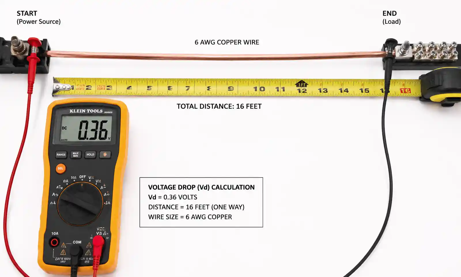
Voltage drop becomes critical for electric vehicle chargers, where a 7.2kW Level 2 charger draws 30 amps continuously. A garage located 80 feet from the main panel would experience 5.4V drop with 8 AWG copper—reducing effective voltage to 234.6V and extending charge time by approximately 3%. Upsizing to 6 AWG reduces voltage drop to 3.4V, maintaining performance within acceptable limits.
For installations exceeding 100 feet, calculate voltage drop using the formula: VD = (2 × K × I × D) / CM, where K is 12.9 for copper or 21.2 for aluminum, I is current in amps, D is one-way distance in feet, and CM is the circular mil area from NEC tables. Many electrical design apps automate this calculation, but understanding the relationship helps explain why aluminum requires larger gauges for long runs.
5. Installation Best Practices and Code Compliance
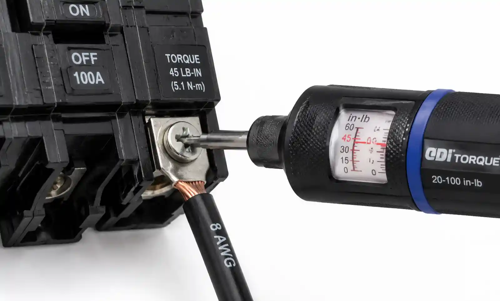
Proper Termination Techniques
Even correctly sized wire fails if terminations are improper. Breaker and device terminals have torque specifications—typically 25-35 in-lbs for residential breakers—and must be tightened with a calibrated torque screwdriver or torque wrench. Overtightening damages conductors and terminals; undertightening creates high-resistance connections that generate heat.
Strip insulation to the exact length specified by the terminal manufacturer, usually marked on the device. Exposed copper beyond the terminal creates arc flash hazards, while insufficient insertion depth causes poor contact. For stranded wire, twist the strands clockwise before insertion so that tightening the terminal screw doesn't unwind the bundle.
Aluminum conductors require additional steps. Apply a thin layer of antioxidant compound to all exposed aluminum surfaces before making connections. Use only terminals marked AL or AL/CU—copper-only terminals will cause galvanic corrosion. Torque aluminum connections 20% higher than copper to ensure proper contact through the oxide layer. Re-torque aluminum connections during the first annual inspection, as aluminum's thermal expansion can loosen connections over time.
Conduit and Raceway Selection
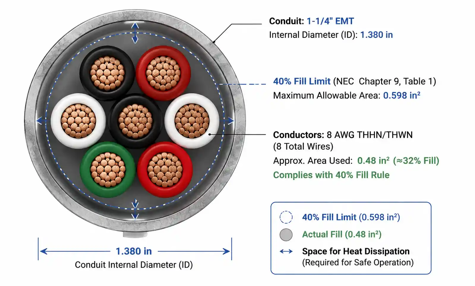
NEC Chapter 9, Table 1 limits conduit fill to 40% for three or more conductors. For 8 AWG THHN copper (0.0366 sq in per conductor), a circuit with three current-carrying conductors plus ground requires at least 3/4-inch conduit. If you're running multiple circuits in parallel, calculate total conductor area and verify against conduit fill tables.
PVC conduit is suitable for most residential underground runs but degrades under UV exposure unless rated for sunlight resistance. EMT (electrical metallic tubing) is standard for exposed indoor runs, while rigid metal conduit (RMC) is required for high-risk mechanical damage areas. For outdoor installations in hot climates, avoid PVC unless buried—surface-mounted PVC in Arizona or Texas can reach 80°C, requiring significant ampacity derating.
Grounding and Bonding
Equipment grounding conductor size must match NEC Table 250.122 based on the overcurrent device rating, not the wire size. For a 40-amp breaker, the minimum copper grounding conductor is 10 AWG. However, if you upsize phase conductors for voltage drop or derating, many engineers upsize the ground proportionally to maintain the same impedance ratio.
The grounding conductor must run with the circuit conductors—never use building steel or separate ground paths, as this increases ground fault impedance and can prevent proper breaker operation. For subpanels, remember that neutral and ground must be isolated, with only the main panel bonding neutral to ground.
6. Common Mistakes and How to Avoid Them
Mistake 1: Sizing Wire to the Breaker Rating Alone
Many DIY installers see "40-amp breaker" and install 10 AWG copper (rated 30A at 75°C), assuming it's adequate. This violates NEC requirements for continuous loads and creates a fire hazard. Always size conductors for 125% of continuous loads—minimum 8 AWG copper for most 40-amp circuits. Verify the actual load calculation rather than simply matching wire to breaker.
Mistake 2: Ignoring Temperature Derating in Hot Environments
Attic-mounted equipment like air handler units often connects via wire running through 60°C+ attic spaces. Without temperature correction, 8 AWG copper's 50A capacity drops to 29A—insufficient for a 40-amp circuit. In hot environments, verify ambient temperature and apply NEC Table 310.15(B)(1) correction factors. For attic runs, consider 6 AWG as the baseline regardless of other factors.
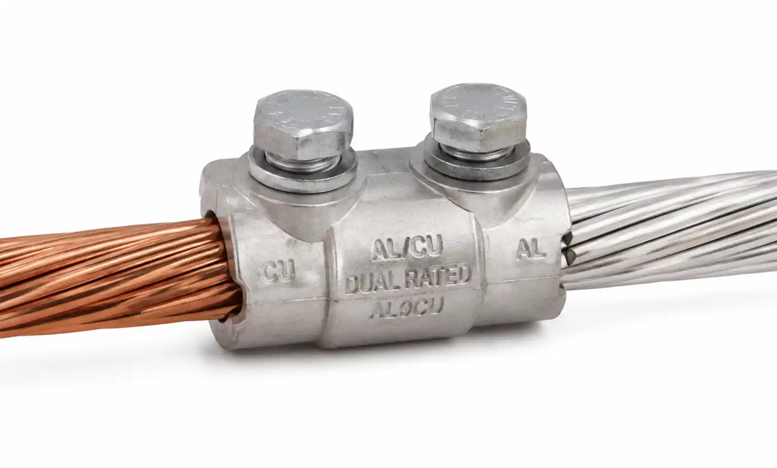
Mistake 3: Mixing Copper and Aluminum Without Proper Terminals
Some installers use aluminum service entrance cable but transition to copper at the first junction box without proper connectors. Direct copper-aluminum contact causes galvanic corrosion and high-resistance connections. Always use terminals rated AL/CU, apply antioxidant compound, and consider using copper-to-aluminum splice connectors rated for the application.
Mistake 4: Neglecting Voltage Drop on Long Runs
Voltage drop doesn't trigger breakers, so it often goes unnoticed until equipment malfunctions. Motors run hot, electronics behave erratically, and LED lights flicker—all symptoms of excessive voltage drop. For any run exceeding 50 feet, calculate voltage drop before selecting wire size. In many cases, the voltage drop constraint requires a larger gauge than ampacity alone would suggest.
Mistake 5: Using 60°C-Rated Wire with 75°C Breakers
Older NM cable (Romex) was rated 60°C, but modern breakers and panels assume 75°C terminations. Using 60°C-rated conductors in a 75°C system effectively downgrades the entire circuit to 60°C ampacity values. Verify that your wire insulation type (THHN, THWN, XHHW) matches the temperature rating of all termination points. When in doubt, check conductor insulation markings printed on the cable jacket.
7. FAQ
What size wire do I need for a 40-amp breaker?
For most residential 40-amp circuits, use 8 AWG copper or 6 AWG aluminum wire with 75°C insulation rating. This sizing accommodates the NEC requirement to size conductors at 125% of continuous loads. If the circuit runs through hot environments like attics, or if the wire run exceeds 64 feet, upsize to 6 AWG copper or 4 AWG aluminum to account for temperature derating and voltage drop.
Can I use 10 AWG wire for a 40-amp circuit?
No. 10 AWG copper is rated for only 30 amps at 75°C and 35 amps at 90°C, both below the 50-amp conductor capacity required for 40-amp continuous-duty circuits. Using 10 AWG creates a code violation and fire hazard. The minimum safe size is 8 AWG copper or 6 AWG aluminum for standard 40-amp installations.
How far can I run 8 AWG wire on a 40-amp circuit?
For copper 8 AWG carrying 40 amps at 240V, limit the one-way distance to approximately 64 feet to stay within the 3% voltage drop recommendation. Beyond this distance, voltage drop degrades performance even though the wire can safely carry the current. For runs of 65-100 feet, upsize to 6 AWG copper. For distances over 100 feet, use 4 AWG or larger.
Do I need to upsize the ground wire if I upsize the phase conductors?
NEC Table 250.122 specifies minimum equipment grounding conductor size based on the overcurrent device rating, not the phase conductor size. For a 40-amp breaker, 10 AWG copper ground meets code. However, many electrical engineers proportionally upsize the ground when phase conductors are increased for voltage drop, maintaining consistent impedance throughout the circuit. This is best practice but not strictly required.
Can I use aluminum wire for a 40-amp circuit in my home?
Yes, aluminum or copper-clad aluminum wire is code-compliant if properly installed. Use 6 AWG aluminum for 40-amp circuits, ensure all terminals are rated AL/CU, apply antioxidant compound to all connections, and torque to manufacturer specifications. Aluminum requires more careful installation than copper, but when done correctly, it's safe and cost-effective, especially for long runs where the cost savings are significant.
What happens if I undersize wire for a 40-amp circuit?
Undersized conductors overheat under load, degrading insulation and creating fire risk. The breaker may not trip because it only protects against overcurrent beyond 40 amps, not chronic overheating of undersized wire. Symptoms include warm wire insulation, burnt smells near junction boxes, and eventual insulation failure. Always size wire according to NEC ampacity tables with appropriate derating factors applied.
Is 8 AWG wire sufficient for an electric vehicle charger on a 40-amp circuit?
For most residential EV charger installations within 50 feet of the panel, 8 AWG copper meets code requirements. However, EV chargers are continuous loads, and many installations benefit from 6 AWG copper to minimize voltage drop and provide margin for future higher-power vehicles. If the garage is more than 60 feet from the panel, or if the charger will be in a hot environment, use 6 AWG as the baseline.
How do I calculate ampacity derating for multiple circuits in one conduit?
Count all current-carrying conductors (phases and neutral if it carries unbalanced current). Apply NEC Table 310.15(B)(3)(a) adjustment factors: 80% for 4-6 conductors, 70% for 7-9, 50% for 10-20. Divide your required ampacity by this factor to determine the conductor's baseline ampacity before derating. For example, a 40-amp circuit in conduit with 8 total conductors needs wire rated for 40A ÷ 0.7 = 57A, requiring 6 AWG copper instead of 8 AWG.
8. Conclusion
Selecting the correct wire size for 40-amp circuits requires evaluating conductor material, installation environment, circuit length, and load characteristics—not just matching wire to breaker rating. For typical residential applications within 50 feet of the panel, 8 AWG copper or 6 AWG aluminum meets code requirements. When circuits run through hot environments, involve long distances, or include multiple conductors in shared raceways, upsizing to 6 AWG copper or 4 AWG aluminum ensures safe operation and code compliance.