


AC Adapter Selection Guide: Engineering Parameters, Efficiency Standards, and Application Scenarios
Selecting the right AC adapter for your electronic design requires balancing multiple technical parameters, efficiency requirements, and application-specific constraints. Whether you're designing consumer electronics, industrial equipment, or medical devices, understanding key specifications and trade-offs is critical for system reliability, regulatory compliance, and cost optimization. This guide provides a structured approach to AC adapter selection based on real-world engineering considerations.
Table of Contents
- What is an AC Adapter and Why Selection Matters
- Key Technical Parameters Explained
- Efficiency Standards and Regulatory Requirements
- How to Choose the Right AC Adapter for Your Application
- Performance Comparison and Trade-offs
- Design Considerations and Common Pitfalls
- Supply Chain and Sourcing Considerations
- FAQ
- Conclusion and Next Steps
1. What is an AC Adapter and Why Selection Matters
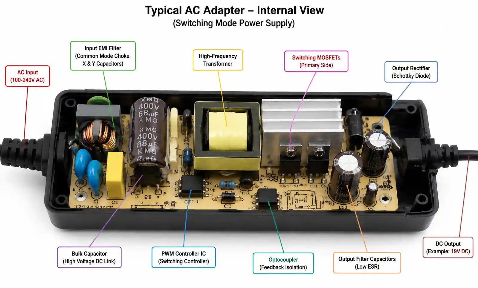
An AC adapter, also known as an AC-DC power supply or wall adapter, converts alternating current (AC) from a wall outlet into direct current (DC) required by electronic devices. The term encompasses a wide range of power conversion topologies, from simple linear regulators to sophisticated switch-mode power supplies (SMPS).
The selection process directly impacts three critical design dimensions. First, system reliability depends on the adapter's ability to handle input voltage variations, load transients, and thermal stress over the product's lifetime. Second, regulatory compliance requirements vary by target market and application, with medical devices requiring IEC 60601-1 certification while consumer products need UL/CE/FCC approval. Third, total cost of ownership includes not just the adapter purchase price but also efficiency-related energy costs, warranty claims, and potential redesign expenses if initial selection proves inadequate.
A common mistake in early-stage design is selecting an adapter based solely on output voltage and current ratings without considering efficiency class, no-load power consumption, or transient response characteristics. This often leads to regulatory delays, thermal management issues, or field failures when the product scales to production.
2. Key Technical Parameters Explained
Understanding the relationship between input specifications, output characteristics, and protection features is essential for proper AC adapter selection. Each parameter affects system behavior under different operating conditions.
Input Specifications
Input voltage range determines geographic compatibility and robustness against power line variations. Universal input adapters (85-265VAC) work globally but typically cost 15-25% more than fixed-input designs. Input frequency tolerance (47-63Hz) matters for applications deployed in regions with unstable grid infrastructure or generator-powered sites.
Input current rating affects circuit breaker sizing and inrush current management. Peak inrush current during power-on can reach 30-50A for a brief moment, requiring careful coordination with upstream protection devices. Power factor correction (PFC) becomes mandatory above 75W in many markets, adding cost but reducing harmonic distortion on the AC line.
Output Specifications
Output voltage tolerance directly impacts downstream circuit margins. A ±5% tolerance may seem acceptable, but combined with cable voltage drop and load regulation errors, the actual voltage at the device input can deviate significantly from nominal. For sensitive analog circuits or precision references, specify ±3% or tighter.
Output current rating must account for peak load conditions, not just average consumption. If your device draws 2A steady-state but peaks to 3A during startup or processing bursts, specify a 3.5-4A adapter to avoid current limiting or thermal shutdown. Continuous operation at 90-95% of rated current reduces adapter lifetime due to elevated component temperatures.
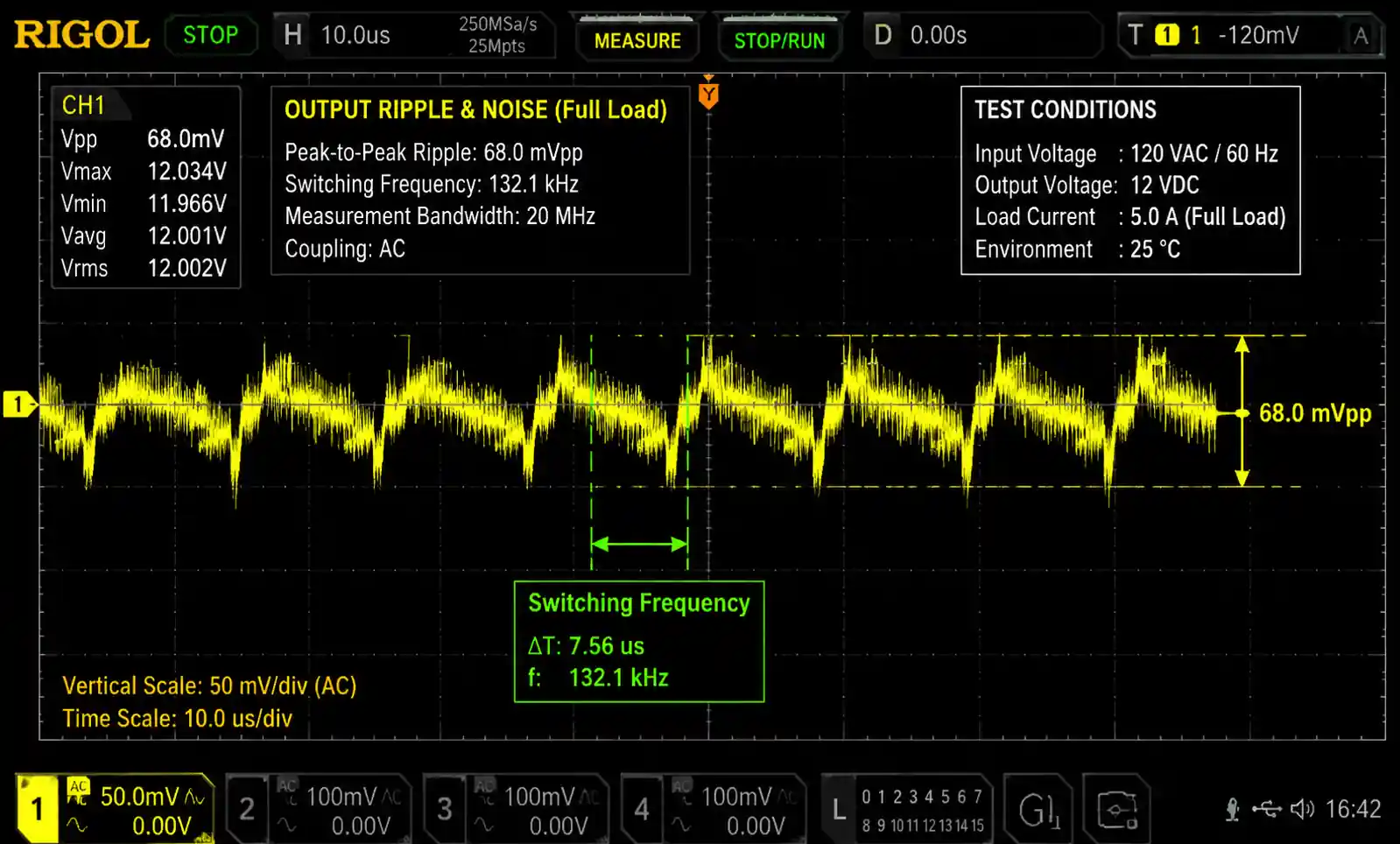
Ripple and noise specifications matter for noise-sensitive applications. Switching frequency ripple (typically 50-150mV peak-to-peak at 50-150kHz) can couple into analog signal paths or clock circuits. High-frequency noise spikes (5-20mV) require additional filtering for RF or precision measurement equipment.
Protection Features
Modern AC adapters integrate multiple protection circuits, but implementation quality varies significantly. Over-voltage protection (OVP) should trip at 110-130% of nominal output, protecting downstream components from damage. Over-current protection (OCP) typically activates at 110-150% of rated current, with hiccup mode preventing sustained fault conditions.
Over-temperature protection (OTP) triggers at internal temperatures of 90-110°C, but this doesn't guarantee safe case temperatures. For applications in enclosures with limited airflow, verify the adapter can deliver full power at your worst-case ambient temperature, typically 40-50°C for consumer products and 60-70°C for industrial applications.
| Parameter | Consumer Grade | Industrial Grade | Medical Grade |
|---|---|---|---|
| Input voltage range | 100-240VAC ±10% | 85-265VAC | 100-240VAC ±10% |
| Output voltage tolerance | ±5% | ±3% | ±2% |
| Ripple and noise (pk-pk) | <150mV | <100mV | <50mV |
| MTBF (hours) | 30,000-50,000 | 100,000-200,000 | >200,000 |
| Operating temperature | 0 to +40°C | -20 to +70°C | +5 to +40°C |
| Safety certifications | UL, CE, FCC | UL, CE, CB | IEC 60601-1, UL 60950-1 |
This comparison shows that while consumer-grade adapters meet basic requirements for controlled environments, industrial and medical applications demand tighter specifications and extended operating ranges. The MTBF difference of 4-7x translates directly to warranty costs and field reliability.
3. Efficiency Standards and Regulatory Requirements
Efficiency standards have evolved rapidly over the past decade, driven by environmental regulations and energy cost concerns. Understanding current requirements prevents costly redesign cycles and market access delays.
DoE Level VI and International Standards
The U.S. Department of Energy (DoE) Level VI standard, effective since 2016, sets minimum average efficiency and maximum no-load power consumption for external power supplies. For a typical 60W adapter, Level VI requires approximately 87% average efficiency and less than 0.1W no-load consumption. European CoC Tier 2 and China CCC standards impose similar requirements with minor variations in test procedures.
Compliance requires testing at multiple load points (25%, 50%, 75%, and 100% of rated power) across the full input voltage range. A design that meets efficiency targets at 115VAC may fail at 230VAC due to different loss distributions in the transformer and switching components. Always verify performance across the entire input specification.
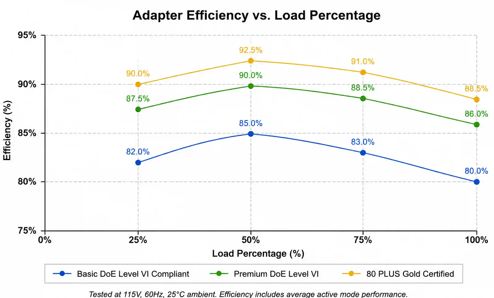
80 PLUS certifications (Bronze, Silver, Gold, Platinum, Titanium) originated for computer power supplies but increasingly serve as benchmarks for high-efficiency adapters. An 80 PLUS Gold adapter maintains >87% efficiency at 20% load, >90% at 50% load, and >87% at 100% load. This matters for battery-powered equipment where adapter efficiency directly affects charging time and energy costs.
Safety and EMC Certifications
Safety certification requirements vary by target market and application category. UL 62368-1 (replacing UL 60950-1) covers information technology equipment in North America. CE marking requires compliance with Low Voltage Directive (LVD) and EMC Directive in Europe. CB scheme certificates facilitate multi-country approvals but don't eliminate local testing requirements.
EMC compliance presents challenges beyond basic safety. Class B emission limits (residential environments) are 10dB stricter than Class A (industrial). Conducted emissions at switching frequencies (typically 50-150kHz and harmonics) require careful input filter design. Radiated emissions can couple through DC output cables, making cable length and routing part of the compliance test setup.
Medical applications require IEC 60601-1 certification with additional requirements for leakage current, isolation voltage, and component reliability. Leakage current limits of 100-300µA (depending on application) are 10-30x stricter than industrial standards, requiring specialized isolation transformers and Y-capacitor selection.
| Standard | Region/Market | Key Requirements | Typical Cost Impact |
|---|---|---|---|
| DoE Level VI | USA | Min. efficiency, max. no-load power | Baseline |
| CoC Tier 2 | Europe | Similar to DoE Level VI | +0-5% |
| CCC | China | Efficiency + safety + EMC | +10-15% |
| IEC 60601-1 | Medical (global) | Leakage current, isolation, MOPP/MOPD | +30-50% |
| UL 62368-1 | North America | Hazard-based safety | +5-10% |
| 80 PLUS Gold | High-efficiency benchmark | >87% at 20%, >90% at 50% | +15-25% |
The cost impact column reflects manufacturing and certification expenses compared to a basic DoE Level VI compliant design. Medical certification adds significant cost not just from testing but also from required design margins and component selection constraints.
4. How to Choose the Right AC Adapter for Your Application
Effective adapter selection follows a systematic process that considers electrical requirements, environmental conditions, regulatory constraints, and supply chain factors. Skipping steps or making assumptions leads to late-stage design changes.
Step 1: Define Load Requirements with Margin
Start by characterizing your actual load profile, not just nominal power consumption. Measure or simulate startup inrush current, peak operating current, and transient load steps. Add 20-30% margin to the maximum observed current for a robust design. If your peak load is 2.5A, specify a 3A minimum adapter rating.
For battery charging applications, the adapter must supply both the charging current and system operating current simultaneously. A device that consumes 1A while charging a battery at 2A requires a 3A minimum adapter, plus margin. Failing to account for this is a common cause of slow charging complaints or system instability during heavy use.
Step 2: Select Voltage Based on Distribution and Regulation
Output voltage selection involves trade-offs between transmission efficiency, downstream regulator headroom, and safety considerations. Higher DC voltages (19V, 24V) reduce cable losses and allow smaller wire gauge, but require more downstream voltage conversion steps. Lower voltages (5V, 12V) simplify USB compatibility and reduce shock hazards but increase cable current and resistive losses.
For long cable runs (>2 meters), calculate voltage drop using: ΔV = I × R_cable. A 2A load through 3 meters of 22AWG wire (0.052 Ω/meter) drops 0.31V. With a 5V adapter, this 6% drop may violate downstream voltage margins. Using a 12V adapter reduces the percentage drop to 2.6%.
Step 3: Match Efficiency Class to Application
Choose efficiency class based on operating duty cycle and energy cost sensitivity. For devices used 24/7 (network equipment, security systems, industrial monitoring), premium efficiency pays back through reduced energy costs. A 10W adapter used continuously at $0.12/kWh costs approximately $10.50/year at 80% efficiency versus $9.60/year at 88% efficiency. Over a 10-year product life, the $9 savings per unit may justify the higher adapter cost.
For intermittent-use devices (power tools, portable equipment), no-load consumption matters more than load efficiency. An adapter drawing 0.5W no-load instead of 0.1W wastes 3.5kWh/year if plugged in continuously, costing $0.40/year. Multiply by millions of units, and the impact becomes significant.
Step 4: Evaluate Environmental and Mechanical Fit
Operating temperature range must match worst-case installation conditions. An adapter rated for 0-40°C may fail in an industrial enclosure where ambient temperature reaches 55°C. Derating curves typically show 50-70% power capability at 60°C. Either select an industrial-grade adapter or ensure adequate ventilation.
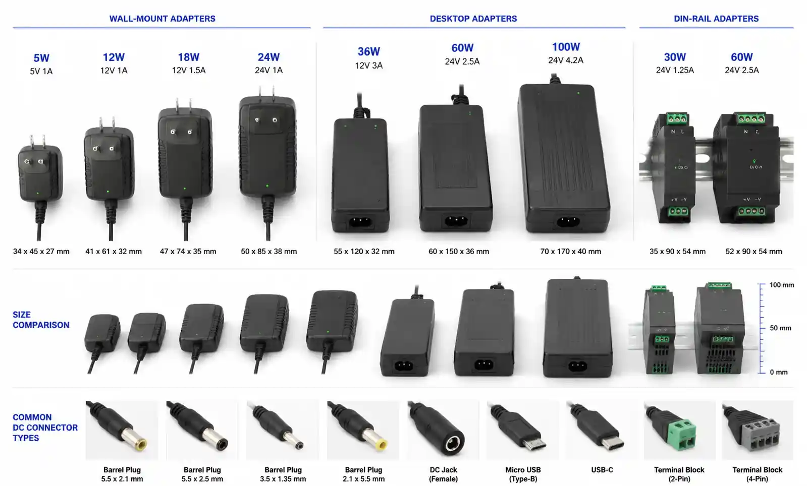
Mechanical considerations include connector type, cable length, and form factor. Barrel connectors (5.5mm/2.1mm, 5.5mm/2.5mm) dominate low-power applications but offer poor retention force. Locking connectors or USB Power Delivery (USB-PD) provide better reliability for mobile equipment. Cable length affects voltage drop and EMC test results, so specify the actual installed length, not just "2 meters minimum."
| Application Type | Voltage | Current | Efficiency Target | Key Considerations |
|---|---|---|---|---|
| IoT sensor nodes | 5V, 12V | 0.5-2A | DoE Level VI | Low no-load power, cost-sensitive |
| Industrial controllers | 24V | 2-5A | 85-88% | Wide temp range, high MTBF |
| Medical devices | 12V, 15V | 1-3A | >88% | IEC 60601-1, low leakage current |
| Consumer electronics | 5V, 9V, 12V | 2-6A | DoE Level VI / 80+ Gold | USB-PD compatibility, compact size |
| Networking equipment | 12V, 19V, 24V | 3-10A | >87% | 24/7 operation, high reliability |
| Battery charging | Application-specific | 2-8A | >85% | CC/CV profile, thermal management |
This table provides starting points for common application categories, but always validate against your specific requirements and worst-case operating conditions.
5. Performance Comparison and Trade-offs
Understanding the trade-offs between different adapter architectures and specification choices helps optimize for your most critical requirements. No single adapter design excels in all dimensions simultaneously.
Linear vs. Switching Topologies
Linear adapters use a transformer to step down AC voltage followed by rectification and linear regulation. They offer low electromagnetic interference, minimal output noise (<5mV), and simple design but suffer from poor efficiency (40-60%) and large size due to the 50/60Hz transformer. These characteristics limit modern use to very low power (<5W) or noise-critical applications like audio equipment and precision measurement.
Switching adapters (SMPS) use high-frequency switching (50-150kHz or higher) for efficient power conversion. Efficiency ranges from 80-94%, enabling compact designs with power densities of 5-15W per cubic inch. The primary trade-offs are increased output ripple (50-150mV), potential EMI issues, and higher cost for proper EMC compliance. For the vast majority of applications above 10W, switching adapters are the only practical choice.
Fixed vs. Universal Input
Fixed input adapters (115VAC or 230VAC) cost 10-20% less than universal input designs due to simpler transformer design and reduced component stress. However, they require separate SKUs for different markets and complicate global distribution. Universal input adapters (85-265VAC) accept any worldwide voltage, simplifying inventory and supporting travel use, but pay a penalty in efficiency (1-3% lower) and slightly larger size.
The break-even point typically occurs around 5,000-10,000 units. Below this volume, the cost of maintaining two fixed-input SKUs exceeds the per-unit savings. Above this volume, fixed-input designs may reduce total cost if your product sells primarily in a single market.
Efficiency vs. Cost Trade-off
Moving from DoE Level VI baseline (85-87% typical) to premium efficiency (90-92%) adds $1-3 per adapter depending on power level. This investment makes sense when energy costs dominate over product lifetime or when premium positioning justifies higher BOM cost. Calculate the payback period: a $2 adapter premium saving $1/year in energy costs breaks even in 2 years for continuously-operated equipment.
For applications with intermittent use or short product lifetimes (<3 years), focus on adequate efficiency for regulatory compliance rather than premium performance. The customer never sees the efficiency benefit, and the cost difference goes straight to margin.
| Design Choice | Pros | Cons | Best For |
|---|---|---|---|
| Linear topology | Ultra-low noise, simple EMC | Poor efficiency, large/heavy | Audio, precision analog |
| Switching topology | High efficiency, compact | Ripple/noise, EMC complexity | General purpose >10W |
| Fixed input | Lower cost, better efficiency | Multiple SKUs, no travel use | High-volume, region-specific |
| Universal input | Single global SKU | Higher cost, slightly lower efficiency | Low-volume, travel products |
| Premium efficiency | Lower energy cost, marketing value | +15-30% unit cost | 24/7 operation, premium products |
| Baseline efficiency | Meets regulations, lower cost | Higher energy consumption | Intermittent use, cost-sensitive |
Engineers often over-specify adapters based on worst-case scenarios that rarely occur in practice. A more effective approach validates actual operating conditions through prototype testing or field data from similar products, then specifies accordingly.
6. Design Considerations and Common Pitfalls
Real-world adapter integration involves subtleties that don't appear in simplified datasheets or application notes. These considerations often emerge during EMC testing, thermal validation, or early field deployment.
Cable Voltage Drop and Remote Sensing
A frequently overlooked issue is voltage drop in the DC cable between adapter and device. Using 22AWG wire (0.052Ω/meter) with 3 meters of cable and 3A load creates 0.47V drop one-way, 0.94V round-trip. This 0.94V loss means a 12V adapter delivers only 11.06V at the device input, potentially violating downstream regulator minimum input voltage requirements.
Solutions include increasing wire gauge (20AWG reduces drop by 40%), shortening cable, raising adapter output voltage, or specifying adapters with remote sensing capability. Remote sensing uses separate sense wires to measure voltage at the load, adjusting adapter output to compensate for cable drop. This adds cost but solves the problem for high-current or long-cable applications.
Transient Response and Input Capacitance
When load current steps suddenly (processor waking from sleep, motor starting, flash memory write cycle), the adapter must respond quickly enough to prevent voltage droop below minimum operating levels. Adapter transient response time (typically 200-500µs) may be too slow for sub-100µs load steps, requiring bulk input capacitance at the device.
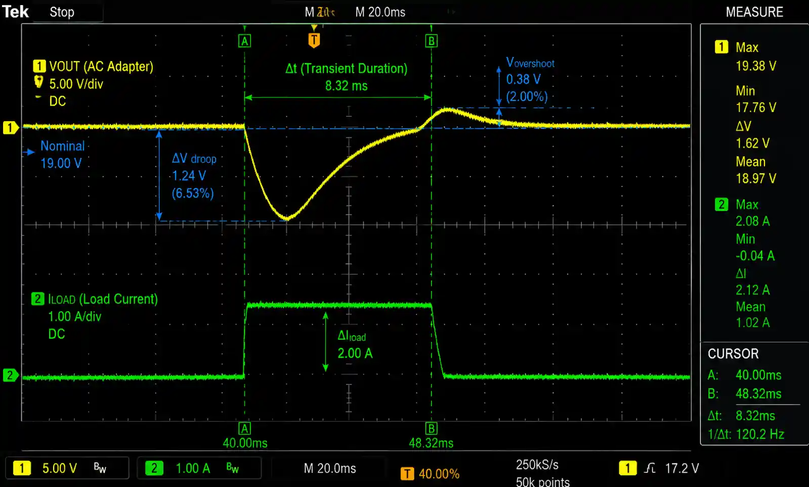
Calculate required capacitance using: C = I × Δt / ΔV, where I is the load step size, Δt is the adapter response time, and ΔV is the acceptable voltage droop. For a 2A load step, 300µs response time, and 0.3V maximum droop: C = 2A × 300µs / 0.3V = 2000µF minimum. Always use aluminum electrolytic or tantalum capacitors with adequate ripple current rating.
Inrush Current Management
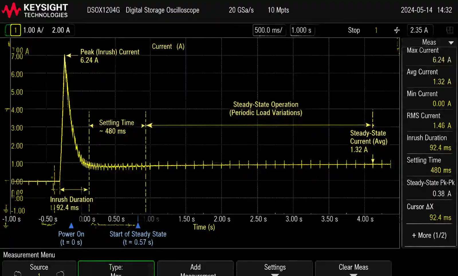
Adapter inrush current at power-on can trip upstream circuit breakers or damage AC switches if not properly managed. Peak inrush of 30-50A occurs when charging the input bulk capacitors with zero voltage across them. This 1-2ms pulse stresses AC connectors and may cause nuisance trips in multi-adapter installations.
Solutions include negative temperature coefficient (NTC) thermistors for passive limiting or active inrush control circuits in premium adapters. Verify the adapter specifies maximum inrush current and duration, especially for applications with multiple adapters on a common circuit or switched AC power distribution.
Thermal Management in Enclosures
An adapter rated for 40°C ambient may reach internal temperatures of 80-90°C at full load. If installed inside a product enclosure, the "ambient" temperature becomes the enclosure internal temperature, which can exceed 55-60°C. The adapter now operates beyond its rating, reducing lifetime and potentially triggering thermal shutdown.
Either select an industrial-grade adapter rated for 70°C ambient, derate the consumer adapter to 50-60% of nominal power, or ensure adequate ventilation and heat sinking. Thermal imaging during worst-case testing catches these issues before field deployment.
Common Design Mistakes
Based on field experience, the most frequent adapter-related failures stem from inadequate margin in current rating (specifying 2A adapter for 2A peak load), ignoring cable voltage drop, insufficient input capacitance for load transients, and operating adapters at elevated ambient temperatures without derating. A 30-minute design review focused on these specific points prevents 70-80% of late-stage problems.
7. Supply Chain and Sourcing Considerations
Technical correctness doesn't guarantee project success if the chosen adapter faces supply chain risks or sourcing challenges. Incorporate these factors early in the selection process.
Lead Time and Availability
Standard catalog adapters from major distributors typically ship within 1-2 weeks for quantities up to 1,000 units. Custom adapters with modified connectors, cable lengths, or labeling require 6-12 weeks lead time and minimum order quantities (MOQ) of 500-3,000 units depending on manufacturer. Plan procurement schedules around these constraints.
Component shortages affecting power semiconductors (MOSFETs, diodes, controllers) can delay adapter production by 3-6 months during shortage cycles. Maintain relationships with multiple suppliers and consider dual-sourcing for production volumes above 10,000 units annually.
Qualification and Reliability Data
Request failure rate data (FIT rate or MTBF) and ask about burn-in testing procedures. Reputable manufacturers perform 100% functional testing plus sample burn-in at elevated temperature (typically 72 hours at 60-70°C). This screens out early failures and validates production quality.
For high-reliability applications, consider requiring manufacturer site audits, process capability data (Cpk), and long-term drift testing. Medical and aerospace applications often mandate these measures, but they add significant cost and schedule.
Counterfeit Risk and Supply Chain Security
Counterfeit adapters pose safety hazards from inadequate isolation, missing protection circuits, and substandard components. When sourcing from distributors or brokers, verify authorized distributor status and require manufacturer certificates of conformance (CoC). Gray market adapters may work initially but fail regulatory testing or exhibit high field failure rates.
For production volumes above 5,000 units, negotiate directly with adapter manufacturers for better pricing, customization options, and supply guarantees. This also reduces counterfeit risk by eliminating distribution intermediaries.
| Sourcing Strategy | Lead Time | MOQ | Cost vs. Standard | Risk Level | Best For |
|---|---|---|---|---|---|
| Catalog / distributor stock | 1-2 weeks | 1-100 units | Baseline +0% | Low | Prototyping, low volume |
| Modified catalog (cable/connector) | 6-8 weeks | 500-1,000 | +10-15% | Low | Mid-volume, minor customization |
| Semi-custom (mech design) | 8-12 weeks | 1,000-3,000 | +20-30% | Medium | High volume, specific form factor |
| Fully custom design | 12-20 weeks | 3,000-5,000 | +40-60% | High | Very high volume, unique specs |
| Multiple suppliers qualified | Varies | Varies | +5-10% NRE | Low | >10,000 units/year, supply security |
Balancing customization against lead time and MOQ requires accurate volume forecasts and understanding of production ramp schedules. Over-customization in early product phases creates supply chain rigidity when design changes occur.
8. FAQ
What is the difference between DoE Level VI and 80 PLUS certifications?
DoE Level VI is a mandatory efficiency standard for external power supplies sold in the United States, requiring minimum average efficiency and maximum no-load power consumption. 80 PLUS is a voluntary certification program originally for internal computer PSUs that specifies efficiency at 20%, 50%, and 100% load points. While DoE Level VI compliance is legally required, 80 PLUS serves as a market differentiator for high-efficiency products.
How do I calculate the required adapter power rating for my device?
Measure or estimate your device's maximum power consumption including all simultaneous loads (processor, display, motors, charging circuits). Add 20-30% margin to account for component tolerances, aging, and transient peaks. For example, if maximum measured consumption is 25W, specify a 30-35W adapter. Verify the adapter can deliver rated power at your worst-case ambient temperature (typically 40°C for consumer, 60°C for industrial).
Can I use a higher voltage adapter than specified?
Only if your device has a voltage regulator with sufficient input voltage headroom. Using a 19V adapter with a device designed for 12V will likely damage components unless protected by a regulator or overvoltage clamp. Always match the adapter voltage to the device specification within ±5% tolerance. Higher current rating is safe; higher voltage rating is not.
What protection features are essential for safety?
At minimum, require over-voltage protection (OVP) to prevent damage from adapter faults, over-current protection (OCP) to limit fault current, and over-temperature protection (OTP) to prevent thermal runaway. For consumer products, short-circuit protection (SCP) adds an extra safety layer. Medical and industrial applications may require additional features like ground fault detection and redundant protection circuits.
How does cable length affect adapter selection?
Longer cables increase voltage drop due to wire resistance, potentially causing the delivered voltage to fall below minimum requirements. Calculate round-trip voltage drop (I × R_cable × 2 × length) and either increase wire gauge, raise adapter output voltage, or limit cable length. For example, 3 meters of 22AWG carrying 3A drops approximately 0.94V, which may violate margin requirements on a 5V or 12V system.
What is the typical lifespan of an AC adapter?
Consumer-grade adapters typically achieve 30,000-50,000 hours MTBF under rated conditions, equivalent to 3-5 years of continuous operation. Industrial-grade adapters reach 100,000-200,000 hours MTBF. Actual lifetime depends heavily on operating temperature, load profile, and input voltage quality. Operating at 80% of rated power and 10°C below maximum temperature can double adapter lifetime.
Do I need power factor correction (PFC)?
PFC is legally required in many markets for power supplies above 75W. Below this threshold, PFC is optional but may still be beneficial for reducing harmonic distortion and improving efficiency. Active PFC (using a boost converter) achieves power factor >0.95 but adds cost. Passive PFC (using filter components) reaches 0.6-0.8 at lower cost. Check target market regulations and application requirements.
How do I verify adapter quality before production commitment?
Request sample units and perform thermal testing at full load and maximum ambient temperature, efficiency measurement at 25%, 50%, 75%, and 100% load, transient response testing with step loads, and ripple/noise measurement with oscilloscope at full load. Verify all certification markings match submitted documentation. For high-volume projects, consider third-party testing lab validation before committing to large orders.
9. Conclusion and Next Steps
Picking the right AC adapter is all about trade-offs: performance, certifications, cost, and availability. Start by understanding your load, add some margin, then test the whole system under the harshest conditions you expect—high temp, low input voltage, full load, long cables. A 2‑to‑4‑hour stress test catches 80% of potential field headaches.
For straightforward needs (standard voltages, commercial temp, DoE Level VI), off‑the‑shelf adapters from big brands are cheap, reliable, and quick to get. If you need industrial temperature ranges, medical safety approvals, or custom mechanicals, loop in the manufacturer early and plan for a longer validation cycle.The real question: what matters most—cost, efficiency, reliability, or supply stability? For most commercial products, a DoE VI adapter with 20‑30% extra power headroom and an industrial‑temp rating hits the sweet spot. Medical, aerospace, or long‑life industrial gear might justify pricier high‑efficiency parts and extended qualification.
Final tip: before you commit, run that worst‑case test with your actual system. It’s a small investment that saves big re-spins later. For more help, check our app notes or reach out to FAE for a design review. We’re happy to take a look.