


BT134 vs BT136: A Complete Technical Comparison for Circuit Designers
Meta Description: Compare BT134 vs BT136 TRIACs for your power control design. Detailed analysis of current ratings, gate sensitivity, thermal performance, and application selection guide for engineers.
Table of Contents
- Introduction: Why BT134 vs BT136 Matters for Your Design
- Key Technical Differences at a Glance
- Detailed Parameter Comparison
- Application Scenario Analysis
- Thermal Management and PCB Layout Considerations
- Cost, Availability, and Supply Chain Factors
- When to Use BT134 vs BT136
- FAQ
- Conclusion
1. Introduction: Why BT134 vs BT136 Matters for Your Design
When designing AC power control circuits for consumer electronics, industrial equipment, or lighting systems, selecting the right TRIAC is critical to achieving reliable performance, thermal stability, and cost efficiency. The BT134 and BT136 are two widely used TRIACs from major semiconductor manufacturers, but they serve different power ranges and application requirements.
This guide helps circuit designers, power electronics engineers, and procurement teams understand the key technical differences between BT134 and BT136, evaluate which device fits specific load conditions, and avoid common design pitfalls. Whether you're controlling a small relay, dimming a lamp, or switching a motor, choosing between these two TRIACs directly impacts your circuit's efficiency, component count, and long-term reliability.
The BT134 is designed for low to medium current applications up to 4A RMS, while the BT136 handles higher currents up to 4A RMS with better surge current capability. Understanding their gate sensitivity, dv/dt ratings, and thermal resistance helps optimize your design for cost, board space, and heat dissipation.
2. Key Technical Differences at a Glance
Before diving into detailed specifications, here's a quick comparison of the most critical parameters that differentiate BT134 from BT136:
| Parameter | BT134 | BT136 | Impact on Design |
|---|---|---|---|
| Max RMS Current (IT(RMS)) | 4A | 4A | Both handle same continuous current |
| Peak Non-Repetitive Surge Current (ITSM) | 25A (20ms) | 25A (20ms) | Similar surge handling capability |
| Gate Trigger Current (IGT) | 5-15mA (typical 10mA) | 5-15mA (typical 10mA) | Comparable gate sensitivity |
| dv/dt Rating | 10V/μs (min) | 10V/μs (min) | Similar commutation performance |
| Maximum Junction Temperature (Tj max) | 125°C | 125°C | Same thermal limit |
| Thermal Resistance (Rθ(j-a)) | 60°C/W | 60°C/W | Similar heat dissipation in free air |
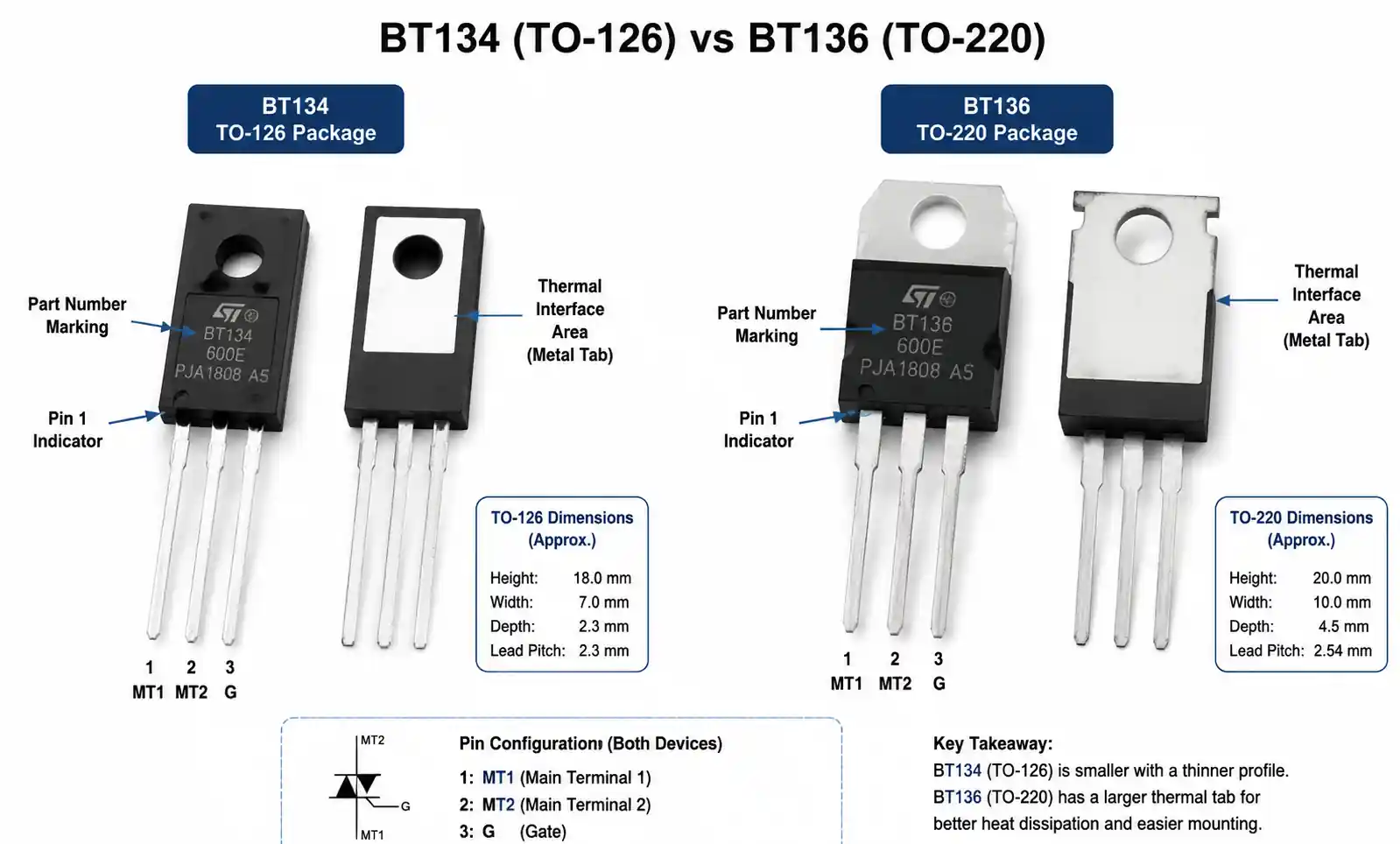
| Package Options | TO-126, SOT-82 | TO-220, TO-220AB | BT136 offers better thermal interface |
| Typical Application Range | Light dimming, small relay | Motor control, heater switching | BT136 preferred for higher power density |
While both TRIACs share similar electrical ratings, the key differentiator lies in their package options and thermal performance under sustained load conditions. The BT136's TO-220 package provides superior heat sinking capability, making it more suitable for continuous high-current applications where thermal management is critical.
3. Detailed Parameter Comparison
Gate Trigger Characteristics
Both BT134 and BT136 feature similar gate trigger requirements, but understanding the nuances helps optimize your drive circuit design. The gate trigger current (IGT) typically ranges from 5mA to 15mA across all quadrants, with most devices triggering reliably at 10mA. However, gate sensitivity varies with temperature and operating quadrant.
In quadrant I (positive voltage, positive gate current) and quadrant III (negative voltage, negative gate current), both devices exhibit the lowest IGT values. In quadrants II and IV, where the gate polarity opposes the main terminal polarity, slightly higher gate current may be required for reliable triggering. For designs operating near the minimum gate current specification, adding a 10-20% margin ensures consistent switching across temperature variations from -40°C to 125°C junction temperature.
The gate-to-MT1 voltage (VGT) typically sits between 0.7V and 1.5V, allowing direct drive from microcontroller outputs through a current-limiting resistor. For a 5V logic signal, a 330Ω to 470Ω resistor provides adequate gate current while staying within the gate power dissipation limit of 0.2W.
Voltage Blocking and Leakage
Both TRIACs are available in voltage grades from 400V to 800V, covering most AC line voltage applications globally. For 120V AC systems, a 400V or 600V device provides sufficient margin. For 230V AC systems, 600V or 800V grades are recommended to handle transient voltage spikes from inductive loads or lightning-induced surges.
Off-state leakage current (IDRM and IRRM) remains below 10μA at rated voltage and 25°C junction temperature, increasing to around 50-100μA at maximum junction temperature. This leakage is negligible in most applications but can become significant in high-impedance gate drive circuits or ultra-low-power standby designs.
On-State Characteristics
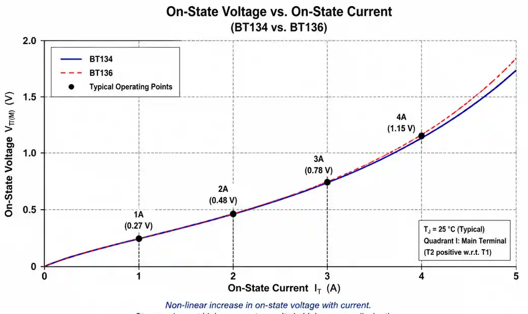
The on-state voltage drop (VT(M)) across both devices is typically 1.2V to 1.5V at rated current, resulting in conduction losses that must be factored into thermal calculations. For a 4A load, this translates to approximately 5-6W of power dissipation in the TRIAC itself.
On-state resistance is not constant but increases with current due to the device's bipolar junction physics. At low currents below 1A, VT(M) may be around 0.9V, while at peak currents near 4A, it can reach 1.5V or higher. This non-linear characteristic affects dimmer linearity and requires careful consideration in precision control applications.
4. Application Scenario Analysis
Residential Lighting Control
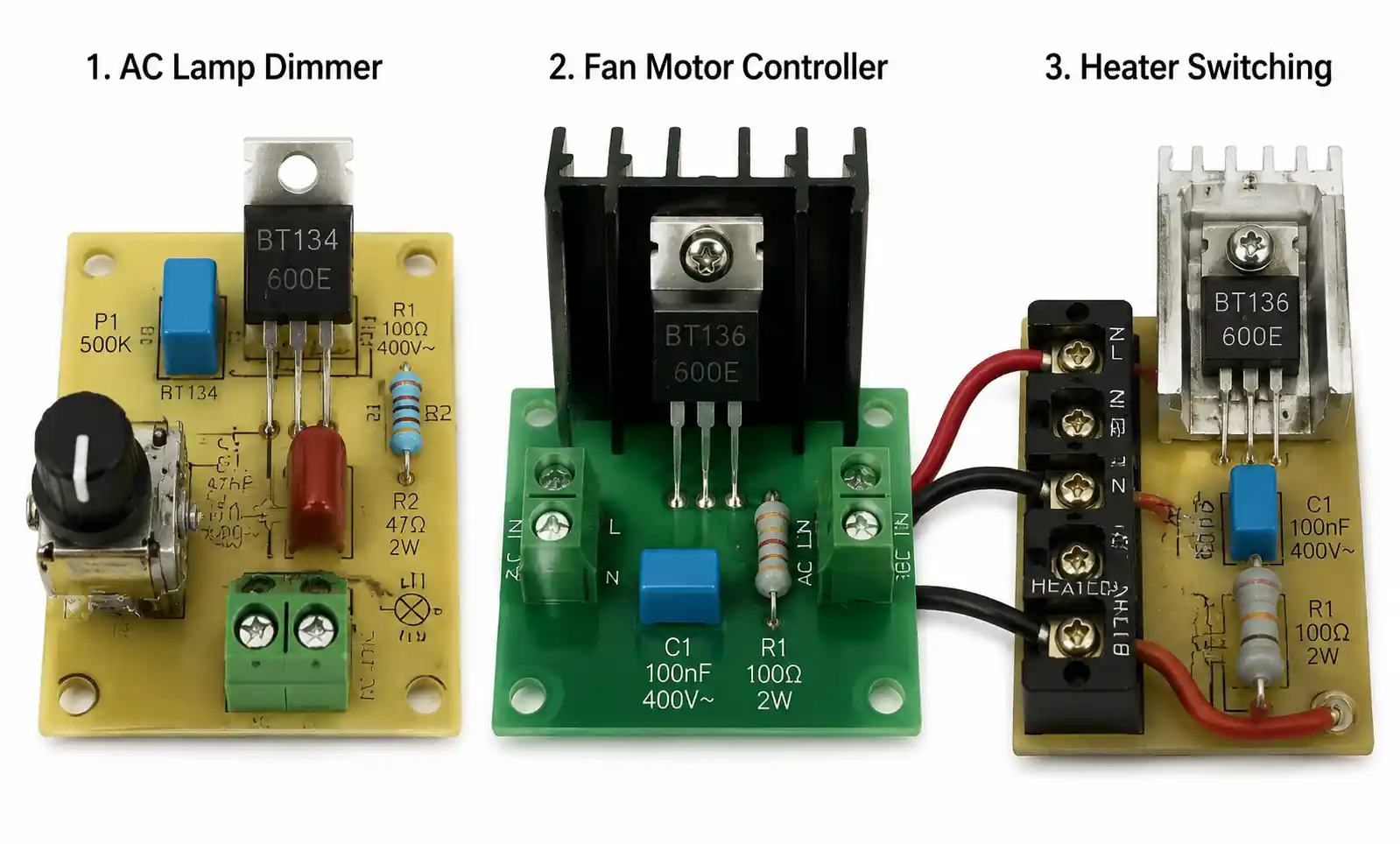
For incandescent lamp dimming and LED-compatible dimmer circuits, both BT134 and BT136 work effectively up to 500W load at 120V AC or 1000W at 230V AC. The choice depends on PCB space constraints and thermal design.
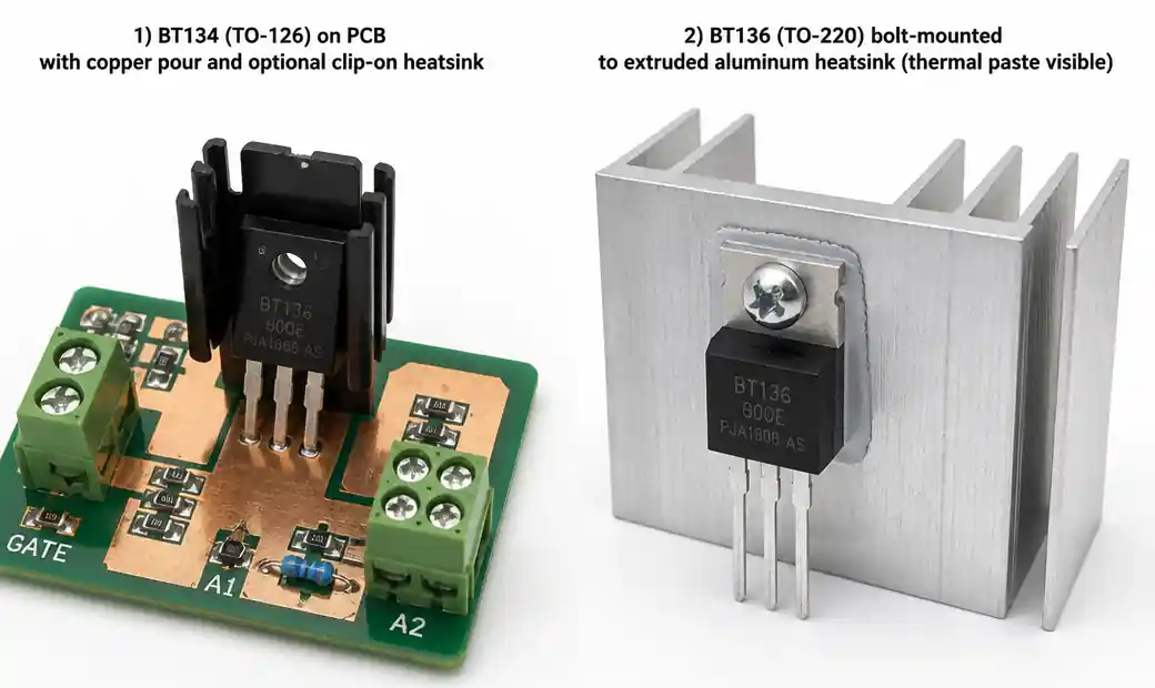
BT134 in TO-126 or SOT-82 package suits compact dimmer designs where the TRIAC is mounted on a PCB with limited heatsink area. Adding a small clip-on heatsink or relying on copper pour for heat spreading can manage the thermal load for typical residential dimming applications with 30-70% duty cycle.
BT136 in TO-220 package is preferred for wall-mounted dimmers handling continuous full-load operation or installations in confined electrical boxes with poor ventilation. The TO-220's bolt-down mounting to a metal enclosure or dedicated heatsink provides superior thermal path, keeping junction temperature well below the 125°C limit even under worst-case conditions.
Small Motor and Fan Control
AC motor control applications, especially for fans, pumps, and small appliances, benefit from the BT136's robust package. Motors present inductive loads with high inrush currents during startup, demanding good surge current capability and thermal margin.
During motor startup, the TRIAC must handle 3-5 times the rated running current for 100-500ms. While both BT134 and BT136 can handle 25A surge current for one half-cycle, repeated starting cycles accumulate thermal stress. The BT136's better thermal coupling to a heatsink allows faster heat dissipation between start cycles, improving reliability in applications with frequent on-off switching.
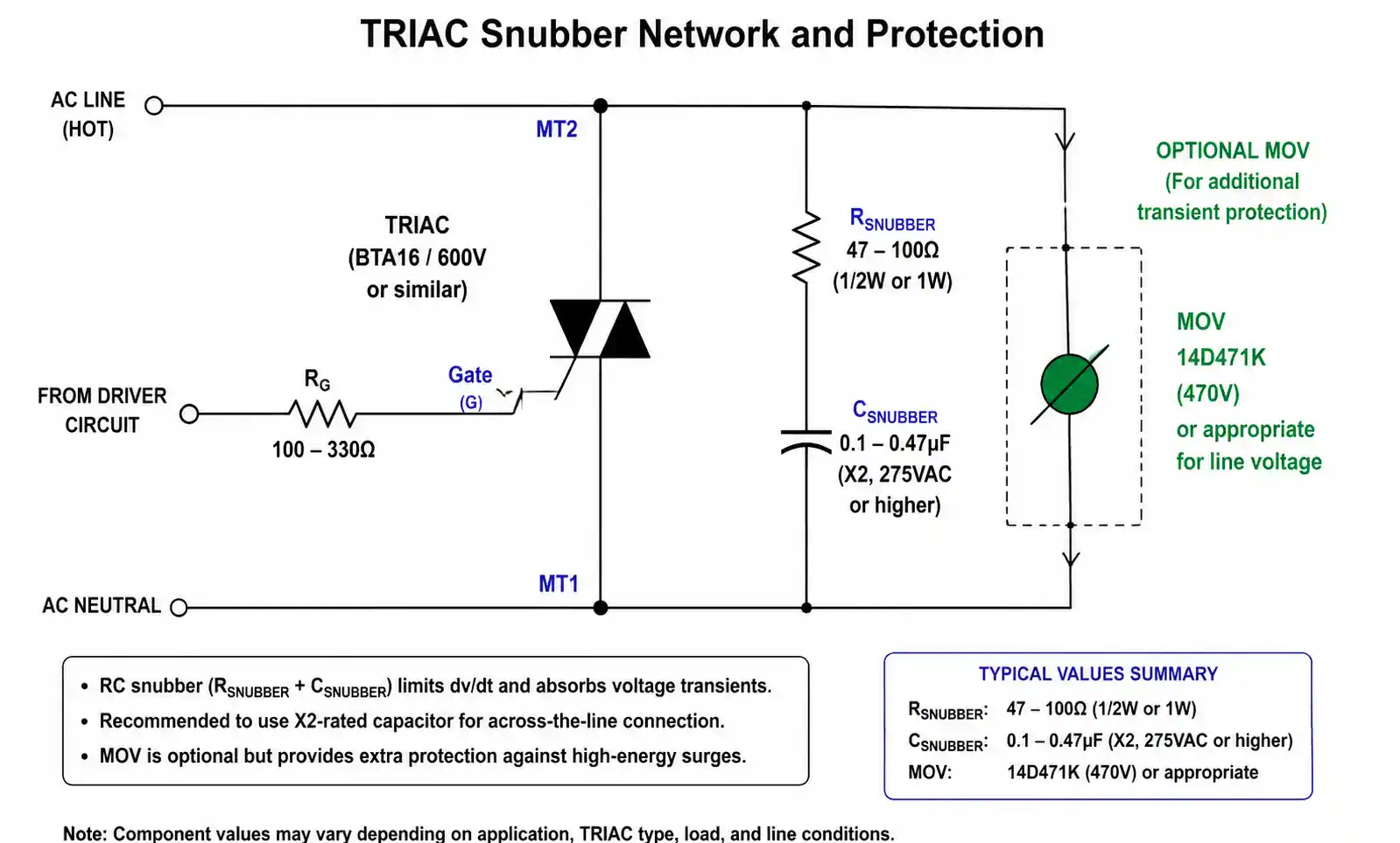
Motor control circuits should include a snubber network (typically 47-100Ω resistor in series with 0.1-0.47μF capacitor) across the TRIAC to suppress voltage transients generated by the motor's inductance. Without proper snubbing, dv/dt during commutation can exceed the TRIAC's rating, causing false triggering or device failure.
Heater and Resistive Load Switching
Resistive loads like electric heaters, toasters, and water heaters are the simplest application for both TRIACs. With no inductive kickback or capacitive inrush, the TRIAC sees a clean sinusoidal current waveform.
For fixed-power heaters operating at full conduction (zero-crossing switching), both BT134 and BT136 perform identically. The choice depends purely on thermal design and cost. If the heater cycles infrequently (thermostatic control with minutes between cycles), even BT134 with minimal heatsinking suffices. For continuous proportional control with phase-angle modulation, BT136 with proper heatsinking is the safer choice to manage sustained power dissipation.
Industrial Relay and Solenoid Control
When controlling electromagnetic relays or solenoids, the TRIAC must handle the coil's inductance and switching transients. Most industrial relays rated for AC operation present inductive loads with power factors between 0.3 and 0.6.
For this application, adding a metal-oxide varistor (MOV) across the load in addition to the TRIAC snubber provides robust protection against voltage spikes that can damage the TRIAC or cause EMI issues. Both BT134 and BT136 work well, but the BT136's TO-220 package simplifies mechanical mounting in industrial control panels where space is less constrained than in consumer products.
| Application Type | Recommended TRIAC | Key Design Considerations |
|---|---|---|
| Lamp Dimming (< 300W) | BT134 (TO-126) | Compact PCB, moderate heatsinking, EMI filtering required |
| Lamp Dimming (> 300W) | BT136 (TO-220) | Enhanced heatsinking, robust snubber network |
| Fan Control (< 100W) | BT134 (TO-126) | Snubber essential, thermal margin for startup surge |
| Fan Control (> 100W) | BT136 (TO-220) | Heatsink mandatory, consider zero-crossing switching |
| Resistive Heaters | BT134 or BT136 | Choose based on thermal design, BT136 for continuous phase control |
| Motor Starters | BT136 (TO-220) | Heavy-duty snubber, MOV protection, adequate heatsink |
| Relay/Solenoid Control | BT134 or BT136 | MOV across load, gate isolation for noise immunity |
After selecting the appropriate TRIAC, validate your choice by calculating actual junction temperature under worst-case conditions, including maximum ambient temperature, maximum load current, and minimum airflow. A safety margin of at least 20°C below the 125°C limit is recommended for long-term reliability.
5. Thermal Management and PCB Layout Considerations
Proper thermal design is critical to TRIAC reliability and longevity. Both BT134 and BT136 have maximum junction temperatures of 125°C, but reaching this limit repeatedly shortens device lifespan. Keeping junction temperature below 100°C under continuous operation significantly improves reliability.
Thermal Resistance and Heatsink Selection
The thermal resistance from junction to ambient (Rθ(j-a)) in free air is approximately 60°C/W for both devices without heatsinking. This means every watt of power dissipation raises junction temperature by 60°C above ambient. For a typical 5W conduction loss at 4A, junction temperature would reach 300°C above ambient without a heatsink, far exceeding the rating.
For BT134 in TO-126 package, mounting the device with its metal tab against a copper PCB pour of at least 10 square centimeters (connected to a ground plane or thermal relief) reduces Rθ(j-a) to approximately 30-40°C/W. Adding a small clip-on heatsink further reduces this to 15-25°C/W.
For BT136 in TO-220 package, bolt-mounting to an extruded aluminum heatsink with thermal interface material (thermal paste or pad) provides Rθ(j-a) values from 5°C/W to 20°C/W depending on heatsink size and airflow. For designs with forced-air cooling, compact heatsinks around 10°C/W are sufficient for 4A operation.
Calculate required heatsink thermal resistance using: Rθ(h-a) = (Tj(max) - Ta(max) - Rθ(j-c) × P) / P, where Tj(max) is the target maximum junction temperature (recommended 100°C), Ta(max) is the maximum ambient temperature, Rθ(j-c) is junction-to-case thermal resistance (typically 1.5-3°C/W for TRIACs), and P is the power dissipation.
PCB Layout Best Practices
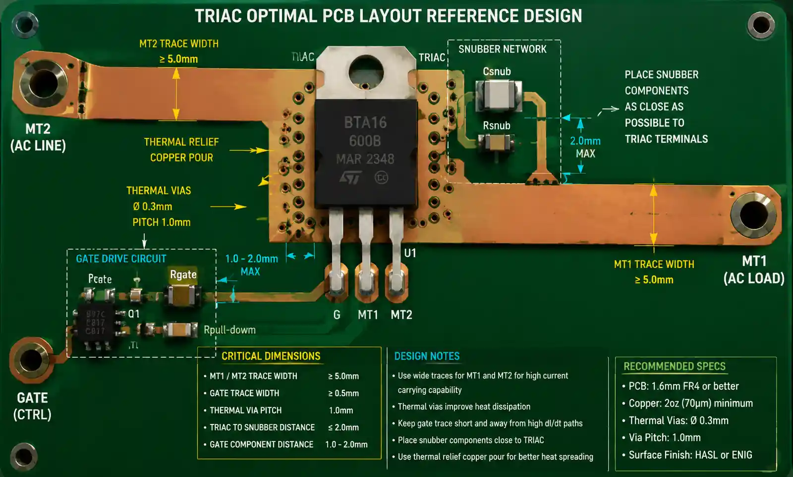
Place the TRIAC close to the gate drive circuit to minimize trace inductance, which can cause voltage spikes during fast switching transitions. Keep gate drive traces short and route them away from high dv/dt nodes to avoid capacitive coupling that might cause false triggering.
Use wide PCB traces for the main current path through MT1 and MT2 terminals. For 4A continuous current, a minimum trace width of 2mm (for 1oz copper) is recommended, but 3-4mm provides better thermal performance and voltage drop margin. If possible, use top and bottom copper layers connected with multiple vias to distribute heat more effectively.
Position the snubber network physically close to the TRIAC terminals to minimize loop area. The snubber's primary function is to limit dv/dt during commutation, and its effectiveness decreases with increased lead inductance. Surface-mount snubber components placed within 5-10mm of the TRIAC terminals provide optimal performance.
For high-reliability designs, add thermal vias under the TRIAC's mounting pad to conduct heat into inner copper layers or to a bottom-side copper pour. A grid of 8-12 thermal vias (0.3mm diameter) significantly improves heat spreading into the PCB.
6. Cost, Availability, and Supply Chain Factors
From a procurement perspective, both BT134 and BT136 are mature, widely available components supplied by multiple manufacturers including STMicroelectronics, NXP, WeEn Semiconductors, and others. This multi-source availability reduces supply chain risk compared to single-source alternatives.
Pricing Comparison
At volume quantities (10,000+ units), BT134 in TO-126 package typically costs $0.08-$0.15 per unit, while BT136 in TO-220 package ranges from $0.12-$0.20 per unit. The price difference reflects the larger die size and package cost of the TO-220 variant.
For cost-sensitive consumer products where thermal requirements allow BT134 usage, the 20-30% cost saving per unit multiplies significantly across production volumes. However, if inadequate heatsinking causes field failures, the cost of returns and warranty claims far exceeds the initial component savings.
Lead Time and Inventory Considerations
Both TRIACs are stocked by major distributors like Digi-Key, Mouser, Arrow, and Avnet with lead times under 2 weeks for standard voltage grades. Higher voltage variants (800V) or specific package options may have longer lead times of 8-12 weeks, requiring advance planning for production schedules.
When designing for manufacturability, consider specifying multiple approved manufacturers in your BOM to allow component substitution without redesign. Both BT134 and BT136 have industry-standard pinouts, making cross-sourcing straightforward as long as the replacement device meets or exceeds all electrical specifications.
Counterfeit Risk Mitigation
TRIACs are unfortunately common targets for counterfeit components in the supply chain. Always source from authorized distributors or directly from manufacturer franchised channels. Key indicators of authentic parts include proper package markings, consistent date codes, and adherence to datasheet specifications during incoming inspection testing.
For critical applications, consider implementing incoming inspection procedures that verify at minimum the forward blocking voltage, gate trigger current, and on-state voltage drop. These parameters are difficult for counterfeiters to replicate accurately and serve as effective screening tests.
7. When to Use BT134 vs BT136
After reviewing technical specifications and application scenarios, the decision between BT134 and BT136 comes down to thermal management, board space, and cost optimization.
Choose BT134 when your application meets these conditions: PCB-mounted design with space constraints, load current averaging below 2-3A continuous, adequate copper area for thermal spreading available, infrequent high-current events with sufficient cool-down time between cycles, and cost optimization is a primary design goal.
Choose BT136 when your application requires: continuous operation at or near 4A rated current, bolt-down mounting to external heatsink or enclosure, improved thermal margin for high-reliability or high-temperature environments, simplified mechanical assembly in industrial control panels, and when the additional cost is justified by reduced thermal stress and improved long-term reliability.
In cases where thermal calculations show borderline performance with BT134, selecting BT136 provides design margin that improves reliability without requiring PCB redesign or additional heatsinking components. This conservative approach often proves more cost-effective over the product lifecycle when accounting for field failure rates and warranty costs.
For new designs, prototype both options if uncertain, and measure actual junction temperature using thermal imaging or thermocouple measurements under worst-case load conditions. Real-world thermal performance often deviates from theoretical calculations due to airflow patterns, enclosure effects, and proximity to other heat-generating components.
8. FAQ
What is the main difference between BT134 and BT136?
The primary difference lies in package options and thermal performance. BT134 is typically available in TO-126 and SOT-82 packages for PCB mounting, while BT136 comes in TO-220 package with superior heatsinking capability. Both share similar electrical ratings (4A RMS current, 25A surge), but BT136's TO-220 package allows bolt-down mounting to heatsinks, making it better suited for sustained high-current applications. The choice depends on your thermal management strategy and available board space.
Can I replace BT134 with BT136 in an existing design?
Yes, but with mechanical considerations. Electrically, BT136 meets or exceeds BT134 specifications, making it a viable upgrade for improved thermal performance. However, the TO-220 package has different footprint and mounting requirements than TO-126 or SOT-82. You'll need to modify the PCB layout and potentially add heatsink mounting provisions. Verify gate drive circuit compatibility and ensure the higher gate capacitance of BT136 doesn't affect switching timing in your application.
How do I calculate the required heatsink for BT136?
Use the thermal resistance formula: Rθ(h-a) = (Tj(max) - Ta(max)) / P - Rθ(j-c), where Tj(max) is your target junction temperature (recommend 100°C for reliability), Ta(max) is maximum ambient temperature, P is power dissipation (approximately VT(M) × IT(RMS)), and Rθ(j-c) is junction-to-case thermal resistance (typically 3°C/W). For example, dissipating 6W with 50°C ambient and 100°C target junction temperature requires heatsink thermal resistance of approximately 5.3°C/W or lower.
Do I need a snubber network with BT134 or BT136?
For inductive loads like motors, fans, transformers, and solenoid coils, a snubber network is essential to prevent false triggering and extend TRIAC lifespan. Typical values are 47-100Ω resistor in series with 0.1-0.47μF capacitor rated for AC line voltage, connected across MT1 and MT2. For purely resistive loads like heaters and incandescent lamps, snubbers are optional but recommended for improved EMI performance and noise immunity. LED and CFL loads may require specialized snubber values due to their non-linear characteristics.
What causes TRIACs to fail in AC switching applications?
Common failure modes include: exceeding maximum junction temperature due to inadequate heatsinking, dv/dt triggering from fast voltage transients without proper snubbing, overvoltage breakdown from transient spikes exceeding rated voltage, overcurrent damage from sustained loads beyond IT(RMS) rating or surge events exceeding ITSM, and gate overvoltage or overcurrent from improper drive circuits. Most failures are preventable through proper thermal design, adequate voltage derating (use 600V device for 230V AC), robust snubber networks, and gate current limiting.
Are BT134 and BT136 suitable for LED dimming applications?
These TRIACs work with many dimmable LED drivers, but compatibility varies by LED driver design. For leading-edge (forward phase) dimming, both TRIACs perform well with loads above their minimum holding current (typically 25-50mA). Some LED drivers present challenging loads with high capacitive inrush or low power factor that can cause flickering or limited dimming range. Test compatibility with your specific LED driver, and consider minimum load requirements—many TRIAC dimmers require 20-40W minimum load for stable operation.
How does temperature affect TRIAC gate sensitivity?
Gate trigger current (IGT) decreases with increasing junction temperature, meaning TRIACs become more sensitive when hot. At -40°C, IGT may reach the maximum datasheet specification (15mA), while at 125°C it drops to minimum values (5mA or lower). Design your gate drive circuit to provide adequate current margin at cold temperatures while staying within maximum gate power dissipation at hot temperatures. A 330-470Ω gate resistor from 5V logic typically provides reliable triggering across the full temperature range.
What are the best alternatives if BT134 or BT136 is out of stock?
Pin-compatible alternatives include: Z0103 series (STMicroelectronics), MAC97A series (ON Semiconductor), T405 and T410 series (STMicroelectronics), BTA series for higher current requirements, and BCR series for sensitive gate applications requiring lower trigger current. Always verify that the replacement device meets or exceeds your original specifications for voltage rating, current rating, gate sensitivity, and dv/dt rating. Check package dimensions carefully as slight variations exist between manufacturers.
9. Conclusion
Choosing between the BT134 and BT136 really comes down to thermal performance, cost, and board space. Both handle 4 A reliably and have similar specs, but the package makes the difference.Go with the BT134 (TO‑126) if you're building compact, cost‑sensitive consumer gear with moderate heat. Pick the BT136 (TO‑220) for industrial applications, motor drives, or anything that runs high current continuously—it dissipates heat much better and lasts longer.
Before you commit, do the math: calculate junction temperature at the worst possible conditions—highest ambient, full load, and minimal airflow. Then verify with real thermal measurements on a prototype. That small step saves you from nasty surprises in the field.For deeper dives, grab the datasheets and app notes. If your design is tricky—gate drive, thermal simulation, etc.—our FAE team is happy to help. Just ask.