


8-Pin Relay Selection Guide: Technical Parameters, Applications, and Design Best Practices
Selecting the right relay for switching applications requires understanding pin configuration, contact arrangements, and electrical ratings. 8-pin relays offer versatile switching configurations suitable for automotive, industrial control, and power management applications. This guide provides engineers and procurement teams with technical insights for choosing, implementing, and sourcing 8-pin relays effectively.
Table of Contents
- What is an 8-Pin Relay and Why Pin Configuration Matters
- Key Technical Parameters Explained
- How to Choose the Right 8-Pin Relay for Your Application
- Performance Comparison by Contact Configuration
- Design Considerations and Common Pitfalls
- Supply Chain and Sourcing Considerations
- FAQ
- Conclusion and Next Steps
1. What is an 8-Pin Relay and Why Pin Configuration Matters
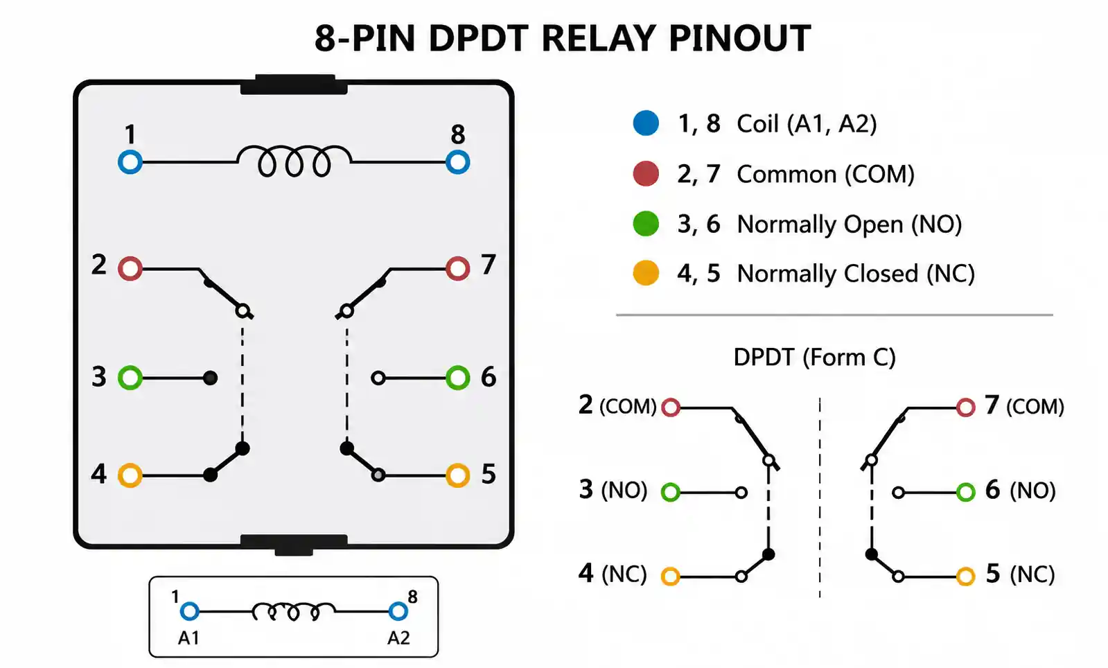
An 8-pin relay is an electromechanical switching device with eight terminal connections, typically arranged in a dual-inline package (DIP) or surface-mount configuration. Unlike simpler 4-pin or 5-pin relays, the 8-pin format accommodates double-pole double-throw (DPDT) contact arrangements, enabling independent control of two separate circuits from a single coil activation.
The pin configuration directly impacts circuit design flexibility. In a typical 8-pin DPDT relay, two pins connect to the coil, while the remaining six pins provide two sets of common, normally open (NO), and normally closed (NC) contacts. This arrangement allows engineers to switch both positive and negative power rails simultaneously, implement fail-safe logic, or control multiple loads with one control signal.
Pin numbering follows industry standards, but verification against the manufacturer datasheet remains essential. Misidentification of coil pins versus contact pins can damage the relay or create unsafe operating conditions. For PCB layout engineers, understanding pin-to-pin spacing and clearance requirements is critical for meeting safety certifications like UL, VDE, or IEC standards.
When evaluating 8-pin relays against alternative configurations, consider that 8-pin DPDT relays provide greater design flexibility than 5-pin SPDT relays while occupying less board space than using two separate single-pole relays. The integrated dual-pole design also improves reliability by ensuring synchronized switching of both poles.
2. Key Technical Parameters Explained
Coil Voltage and Power Consumption
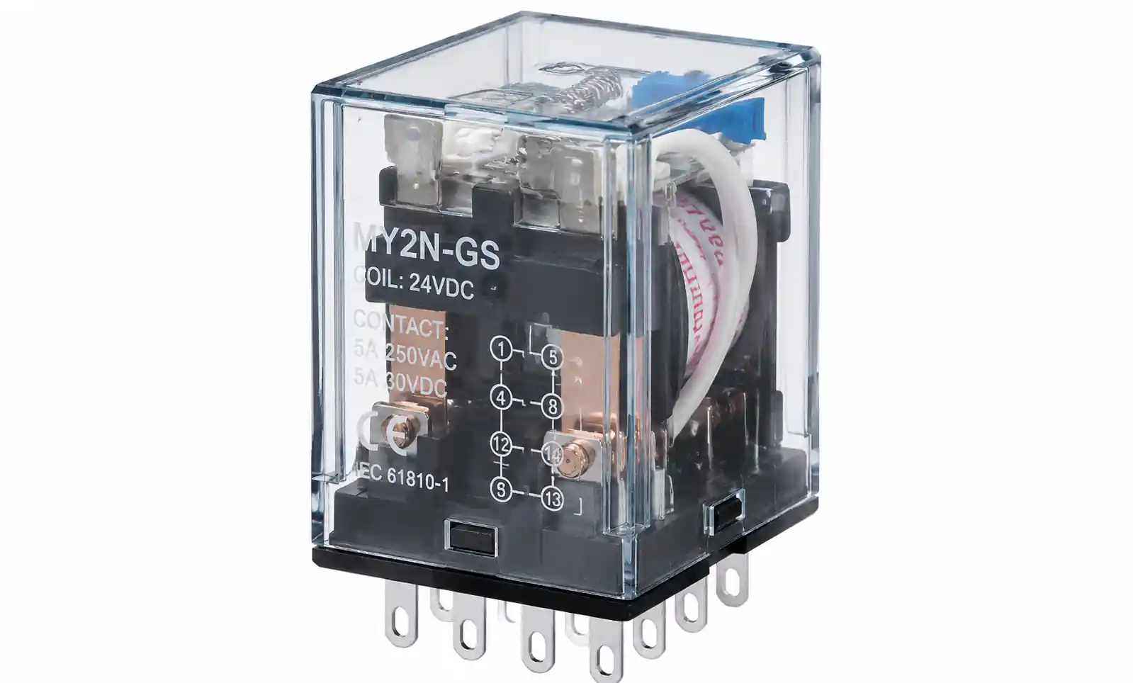
Coil voltage determines relay compatibility with control circuits. Common ratings include 5VDC, 12VDC, 24VDC, and 48VDC for DC-powered designs, or 120VAC and 240VAC for AC control applications. Coil resistance affects power consumption, with typical values ranging from 70Ω to 1000Ω depending on voltage rating. A 12VDC relay with 400Ω coil resistance draws 30mA, while a 5VDC version with 125Ω draws 40mA. In battery-powered or energy-sensitive applications, latching relay variants reduce continuous power draw by requiring only a pulse to change state.
Contact Ratings and Load Types
Contact current ratings define maximum switching capacity. Standard 8-pin signal relays handle 2A to 5A at 250VAC or 30VDC, while power relay versions support 10A to 16A. However, rated current varies significantly with load type. Resistive loads (heaters, incandescent lamps) tolerate full rated current, but inductive loads (motors, solenoids, transformers) require derating to 40-60% of nominal rating due to inrush current and back-EMF. Capacitive loads (LED drivers, power supplies) also demand derating because of high inrush during switch-on.
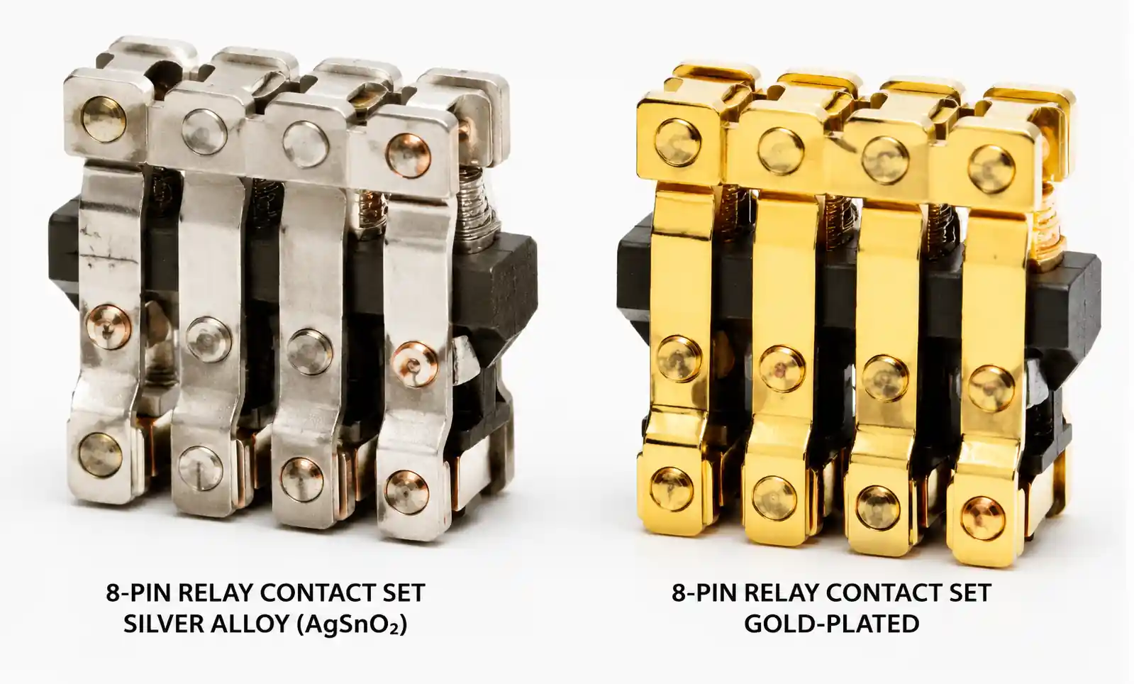
Contact material affects performance and lifespan. Silver alloy contacts (AgNi, AgSnO₂) provide low contact resistance and high conductivity, suitable for power switching applications. Gold-plated contacts minimize contact resistance degradation in low-level signal switching (below 100mA) where oxide formation would otherwise cause signal integrity issues.
Mechanical and Electrical Life
Mechanical life indicates contact durability without electrical load, typically rated at 10 million to 50 million operations for quality 8-pin relays. Electrical life represents expected cycles under rated load conditions, usually 100,000 to 500,000 operations depending on contact material and load characteristics. Switching inductive loads or operating above 80% of rated current significantly reduces electrical life.
Operate and Release Time
Operate time is the interval between coil energization and contact closure, typically 5ms to 15ms for standard relays. Release time, measured from coil de-energization to contact opening, ranges from 3ms to 10ms. High-speed relays reduce these values to under 3ms but often sacrifice contact ratings or mechanical life. In timing-critical applications, contact bounce duration (0.5ms to 2ms) must be factored into circuit design to prevent false triggering of downstream logic.
Dielectric Strength and Isolation Voltage
Dielectric strength defines voltage withstand capability between isolated circuits. Standard 8-pin relays provide 4kVAC isolation between coil and contacts, with reinforced insulation versions offering 5kVAC to 8kVAC for safety-critical applications. This parameter matters in medical devices, industrial control systems, and mains-powered equipment where regulatory compliance demands specific isolation levels.
3. How to Choose the Right 8-Pin Relay for Your Application
Step 1: Define Load Requirements
Begin by characterizing the load. Calculate maximum current including inrush for capacitive loads or startup surge for motors. For inductive loads, apply a 40% derating factor. If switching 3A inductive load, select a relay rated for at least 5A resistive. Verify that contact voltage rating exceeds circuit voltage with adequate safety margin; for 24VDC circuits, a 30VDC contact rating provides minimal headroom, whereas 60VDC or 125VDC ratings offer better reliability.
Step 2: Match Coil Voltage to Control Circuit
Select coil voltage matching your control system. Microcontroller-based designs typically use 5VDC or 3.3VDC coil relays, though 5VDC remains more common due to better availability. Industrial PLCs often employ 24VDC control circuits. When driving relays from logic-level outputs, verify coil current falls within GPIO capability or use a transistor driver circuit. For AC coil relays in mains-voltage control panels, ensure proper isolation and safety interlocks.
Step 3: Evaluate Contact Configuration Needs
DPDT configuration suits applications requiring simultaneous switching of two circuits, polarity reversal, or alternating between two loads. If your design only needs single-circuit switching, consider whether 8-pin DPDT provides value over simpler 5-pin SPDT formats. The dual-pole capability enables creative circuit solutions like H-bridge motor control, redundant safety circuits, or multi-state indicator control.
Step 4: Consider Environmental and Reliability Factors
Operating temperature range affects relay selection for harsh environments. Standard relays function from -40°C to +85°C, while automotive-grade versions extend to +125°C for under-hood applications. Sealed relays with plastic enclosures protect against dust and moisture in industrial environments, though hermetically sealed relays are required for high-humidity or corrosive atmospheres.
Shock and vibration resistance matters in mobile equipment, automotive, and railway applications. Look for relays tested to IEC 68-2-6 (vibration) and IEC 68-2-27 (shock) standards, with typical ratings of 10G vibration resistance and 50G shock resistance for rugged applications.
Step 5: Verify Compliance and Certification Requirements
Safety certifications vary by application and market. UL recognition is essential for North American markets, while VDE or ENEC marks satisfy European requirements. Automotive applications demand AEC-Q200 qualification for temperature cycling, humidity, and mechanical stress. Medical device designs require relays with reinforced insulation and appropriate IEC 60601-1 compliance.
4. Performance Comparison by Contact Configuration
| Parameter | 8-Pin DPDT | 5-Pin SPDT | Dual SPST (4-Pin Each) | Solid-State Relay |
|---|---|---|---|---|
| Number of switchable circuits | 2 independent | 1 | 2 independent | 1 (typically) |
| Typical contact current | 5A to 10A | 5A to 10A | 5A to 10A | 2A to 25A |
| On-state voltage drop | <50mV | <50mV | <50mV | 1V to 1.6V |
| Off-state leakage | <1μA | <1μA | <1μA | 0.1mA to 10mA |
| Switching speed | 5ms to 15ms | 5ms to 15ms | 5ms to 15ms | <1ms (zero-cross) |
| Mechanical life | 10M cycles | 10M cycles | 10M cycles | Unlimited |
| Electrical life | 100K cycles | 100K cycles | 100K cycles | Unlimited |
| PCB footprint | Medium (single package) | Small | Large (two packages) | Small to Medium |
| Cost per switching pole | Low | Lowest | Medium | Medium to High |
| Noise generation | Contact bounce | Contact bounce | Contact bounce | None (silent switching) |
This comparison reveals that 8-pin DPDT relays deliver optimal balance when designs require two synchronized switches. Using a single 8-pin relay instead of two discrete 4-pin relays reduces PCB area, simplifies routing, and ensures simultaneous contact operation. However, solid-state relays offer advantages in high-speed switching or applications where mechanical wear is unacceptable, despite higher on-state voltage drop and off-state leakage.
| Application Scenario | Recommended Configuration | Key Considerations |
|---|---|---|
| Motor direction control (H-bridge) | 8-Pin DPDT | Enables polarity reversal with single relay; add flyback diodes for inductive protection |
| Dual power rail switching | 8-Pin DPDT | Simultaneously switch +V and GND or ±V supplies; check current rating per pole |
| Redundant safety circuit | 8-Pin DPDT | One pole for main circuit, second pole for safety interlock or status indication |
| Single-channel switching | 5-Pin SPDT | More cost-effective; smaller PCB footprint; adequate for simple on/off control |
| High-frequency switching (>100Hz) | Solid-State Relay | Eliminates mechanical wear; silent operation; requires thermal management |
| Low-level signal switching (<10mA) | 8-Pin DPDT with gold contacts | Minimizes contact resistance variation; prevents oxide formation |
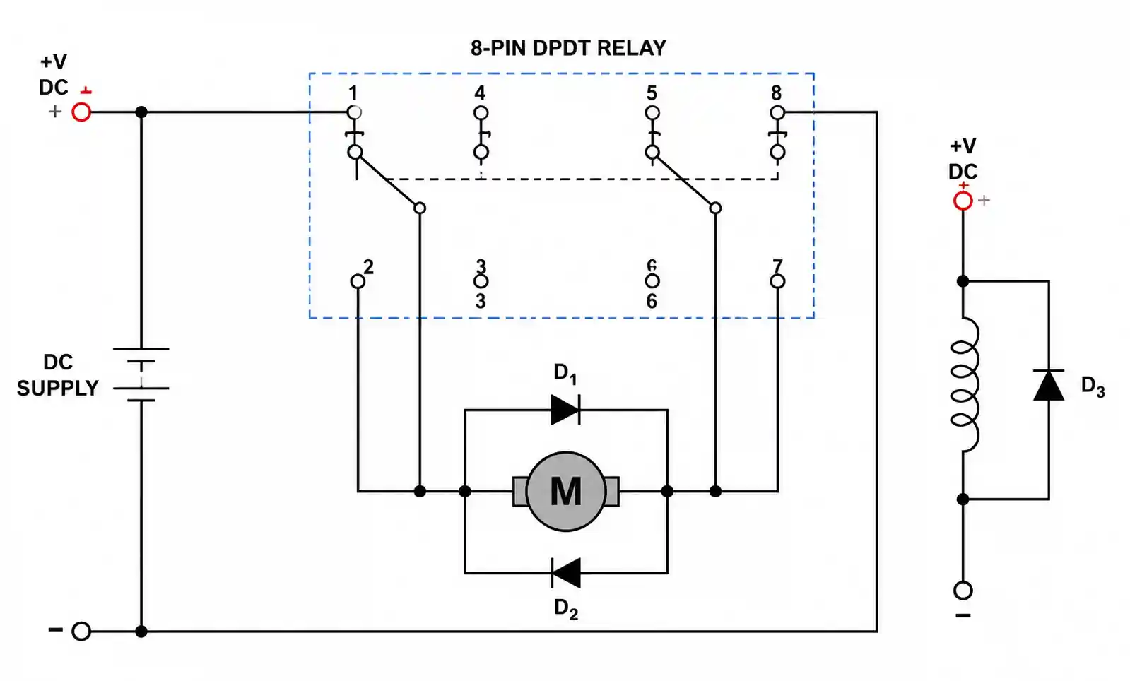
For motor control applications, 8-pin DPDT relays simplify H-bridge implementations by providing both poles needed for forward/reverse operation. In power supply designs switching both positive and negative rails, the synchronized dual-pole action ensures both rails change state simultaneously, preventing potential latch-up or shoot-through conditions.
5. Design Considerations and Common Pitfalls
Coil Suppression is Mandatory for Inductive Coils
Relay coils are inductive loads that generate back-EMF when de-energized. Without suppression, voltage spikes can exceed 10x the coil voltage, damaging driver transistors or microcontrollers. The most common suppression method places a flyback diode across the coil, with cathode to positive coil terminal. For faster coil de-energization, use a Zener diode in series with the flyback diode, setting Zener voltage to 1.5x to 2x coil voltage. RC snubber networks (typical values: 1kΩ + 100nF) provide alternative suppression suitable for AC coil relays.
Contact Arc Suppression Extends Relay Life
When switching inductive loads, contact arcing during break operation gradually erodes contact material. Arc suppression circuits significantly extend electrical life. For DC circuits, a reverse-biased diode across the load redirects inductive energy. For faster turn-off, use a Zener diode or MOV (metal oxide varistor) with breakdown voltage 1.3x to 1.5x supply voltage. AC inductive load suppression typically employs RC snubbers (0.1μF + 100Ω across load) or MOV devices rated for peak circuit voltage.
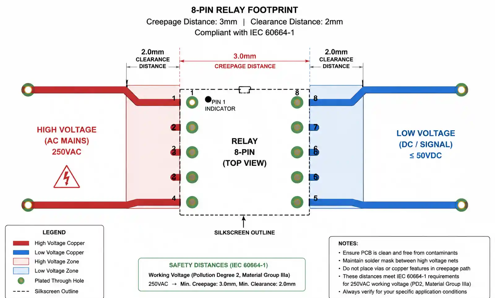
PCB Layout Impacts Performance and Safety
Contact spacing on the PCB must maintain adequate creepage and clearance distances. For 250VAC circuits, IEC 60664-1 requires minimum 3mm creepage (surface distance) and 2mm clearance (air gap) for pollution degree 2 environments. Route high-current contact traces with adequate copper thickness; 2oz copper provides better current handling and thermal dissipation than standard 1oz. Keep coil traces separated from contact traces to minimize coupled noise, especially in sensitive analog or RF circuits.
Parallel Contacts Do Not Double Current Rating
A common mistake is paralleling both poles of a DPDT relay to achieve higher current capacity. Contact operation timing variations mean one contact closes before the other, resulting in uneven current distribution. If paralleling is unavoidable, use individual fusing on each contact path and derate total current to 1.5x single-pole rating rather than 2x.
Relay Chatter in Marginal Coil Voltage Conditions
Operating a relay below its minimum pickup voltage or allowing coil voltage to sag during load switching causes contact chatter. This rapidly cycles contacts, creating arcing and premature failure. Ensure coil supply regulation maintains voltage above 85% of nominal under all load conditions. Add bulk capacitance near relay coils when driving from switched-mode power supplies with significant ripple.
Switching Capacitive Loads Requires Inrush Limiting
LED power supplies, motor drive inverters, and bulk capacitors present high inrush current during initial energization. This inrush can be 10x to 50x steady-state current for 5ms to 50ms, potentially welding relay contacts. Implement inrush limiting with NTC thermistors, series inductors, or soft-start circuits. Alternatively, select relays rated for capacitive load switching with contact materials resistant to welding.
6. Supply Chain and Sourcing Considerations
Lead Times and Availability Challenges
Standard 8-pin relays from major manufacturers (Omron, Panasonic, TE Connectivity, Hongfa) typically maintain 4 to 12 week lead times for volume orders. Generic relay lead times extended during component shortages to 16 to 24 weeks. Maintain strategic inventory of critical relay types or establish relationships with authorized distributors offering consignment stock programs.
| Supplier Type | Typical MOQ | Lead Time | Price Range (100 pcs) | Quality Assurance |
|---|---|---|---|---|
| Direct manufacturer | 1000 to 5000 pcs | 8 to 16 weeks | $0.80 to $2.50 | Full traceability, test reports |
| Authorized distributor | 1 to 100 pcs | Stock to 8 weeks | $1.20 to $3.50 | Manufacturer CoC, authorized warranty |
| Franchise distributor | 1 to 50 pcs | Stock to 4 weeks | $1.50 to $4.00 | Manufacturer-backed, smaller inventory |
| Independent distributor | 1 to 25 pcs | Stock only | $2.00 to $5.00 | Variable; verify authenticity |
| Online marketplace | 1 pc | 3 to 30 days | $1.00 to $6.00 | High counterfeit risk; test required |
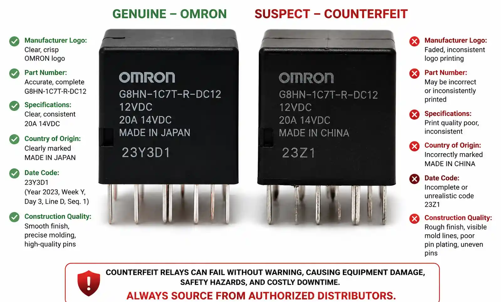
When sourcing for production, prioritize authorized distributors despite slightly higher unit costs. Counterfeit relays represent significant risk in critical applications, with inferior contact materials, inadequate isolation, and falsified safety certifications.
Form, Fit, and Function Alternatives
Establishing alternate manufacturers early in the design phase mitigates supply chain disruption. Many relay manufacturers offer pin-compatible alternatives to popular models. When evaluating substitutes, verify not just mechanical footprint but also coil characteristics (resistance, operate voltage range), contact ratings, and safety certifications. Minor differences in operate/release time can impact circuit behavior in timing-sensitive applications.
Cost Optimization Strategies
For high-volume production, negotiate direct manufacturer relationships with annual purchase agreements. Volume discounts typically begin at 10,000 pieces annually, with pricing reductions of 20% to 40% compared to distributor pricing. Consolidating relay types across product lines reduces SKU count and increases per-part volume, strengthening negotiating position.
Consider regional manufacturing differences. Relays manufactured in Japan or Europe carry premium pricing but offer tightest tolerances and longest life ratings. Chinese manufacturers like Hongfa or Tianbo provide cost-effective alternatives meeting international standards, with pricing 30% to 50% below premium brands while maintaining adequate quality for most industrial and consumer applications.
Quality Verification and Incoming Inspection
For safety-critical applications, implement incoming relay inspection beyond visual checks. Test coil resistance to detect winding defects. Verify operate and release voltages fall within datasheet specifications. Check contact resistance using four-wire measurement to identify contaminated or poorly plated contacts. For high-reliability applications, consider 100% electrical testing or implement statistical sampling at AQL 0.65 or stricter.
7. FAQ
What is the main advantage of an 8-pin relay over simpler relay types?
The 8-pin format typically provides DPDT (double-pole double-throw) contact configuration, allowing simultaneous control of two independent circuits from a single coil. This enables applications like motor direction control, dual power rail switching, or redundant safety circuits that would otherwise require two separate relays.
Can I use an 8-pin relay rated for AC loads in a DC circuit?
Yes, but with considerations. AC-rated contact current often exceeds DC rating at the same voltage because AC current naturally zeros twice per cycle, extinguishing contact arcs. When switching DC inductive loads, derate AC contact rating by 40% to 50% and implement arc suppression to prevent contact erosion.
How do I calculate the required coil driver transistor rating?
Divide coil voltage by coil resistance to determine steady-state current. Add 20% margin for transistor selection. The transistor must withstand coil supply voltage plus back-EMF spike (typically 2x coil voltage with flyback diode protection). For a 12VDC, 400Ω relay drawing 30mA, select a transistor rated for at least 50mA and 30V.
What causes relay contact welding and how do I prevent it?
Contact welding occurs when excessive current or arc energy melts and fuses contact material. Common causes include switching capacitive loads with high inrush current, short circuits, or exceeding contact current rating. Prevent welding by implementing inrush limiting, using arc suppression networks, properly derating contacts for load type, and selecting relays with weld-resistant contact materials like AgSnO₂.
Are 8-pin relays suitable for automotive applications?
Standard 8-pin relays function in automotive environments if they meet AEC-Q200 qualification for temperature cycling, humidity, and vibration. Automotive under-hood applications require extended temperature ratings (-40°C to +125°C) and sealed construction. Verify the specific relay model carries automotive-grade qualification rather than assuming all 8-pin formats are suitable.
What is the difference between mechanical life and electrical life ratings?
Mechanical life indicates expected operations without electrical load, representing physical wear of the contact mechanism. Electrical life reflects operations under rated load conditions, accounting for contact erosion from arcing. Electrical life is always shorter than mechanical life, typically 10x to 100x fewer cycles depending on load characteristics.
How do I implement relay redundancy for safety-critical applications?
Use both poles of the DPDT relay in series for the critical path, so both contacts must close to complete the circuit. This provides redundancy against single-contact failure. Alternatively, use two separate relays with contacts in series, driven by independent control circuits. Include status feedback monitoring contact position to detect failures before they compromise safety.
Can solid-state relays completely replace electromechanical 8-pin relays?
Solid-state relays excel in high-speed switching, silent operation, and unlimited mechanical life but have trade-offs. SSRs exhibit higher on-state voltage drop (1V to 1.6V vs. 50mV), off-state leakage current, and heat generation requiring thermal management. For low-duty-cycle, high-current applications with galvanic isolation requirements, electromechanical relays often remain more practical and cost-effective.
8. Conclusion and Next Steps
Choosing an 8‑pin relay is all about matching contact ratings, coil specs, mechanical fit, and reliability to what your circuit actually needs. The DPDT configuration gives you flexibility—dual‑circuit switching, motor control, or redundant safety paths—which makes it worth the extra space compared to simpler relays.
For power switching with resistive or moderate inductive loads, standard 8‑pin relays are proven and cost‑effective. Just make sure you get the arc suppression right, lay out your PCB with adequate spacing, and derate properly for your load. If you're switching fast or cycling a lot, take a look at solid‑state alternatives too—they have trade‑offs but might be a better fit.
Before you order, grab the datasheet and double‑check electrical specs, dimensions, and safety certs. For automotive, medical, or safety‑critical stuff, confirm the specific model has the right qualifications. And always test with samples under real load before committing to volume.Need help picking, finding app notes, or sorting supply? Talk to an experienced supplier or FAE—they can save you time and reduce design risk.