


8-Pin Relay Selection Guide: Technical Specifications and Application Design
Selecting the right relay configuration for your circuit design directly impacts system reliability, switching performance, and long-term cost. Among the various relay pin configurations available, 8-pin relays offer distinct advantages for applications requiring dual coil control, bidirectional switching, or separate NO/NC contact isolation. This guide helps design engineers, circuit designers, and procurement teams understand when an 8-pin relay is the optimal choice and how to specify it correctly.
Table of Contents
- What is an 8-Pin Relay and When Should You Use It?
- Key Technical Parameters Explained
- 8-Pin vs 5-Pin vs 4-Pin Relay: Configuration Comparison
- How to Select the Right 8-Pin Relay for Your Application
- Design Considerations and Common Pitfalls
- Supply Chain and Sourcing Considerations
- FAQ
- Conclusion and Next Steps
1. What is an 8-Pin Relay and When Should You Use It?
An 8-pin relay is an electromechanical or solid-state switching device with eight terminal connections, typically arranged in a dual-inline package (DIP) or surface-mount configuration. Unlike simpler 4-pin or 5-pin relays that offer single-pole single-throw (SPST) or single-pole double-throw (SPDT) switching, 8-pin relays provide additional functionality through one of three common configurations: dual-coil single-pole double-throw (DPDT with dual coils), dual-pole double-throw (DPDT), or latching relay with set/reset coils.
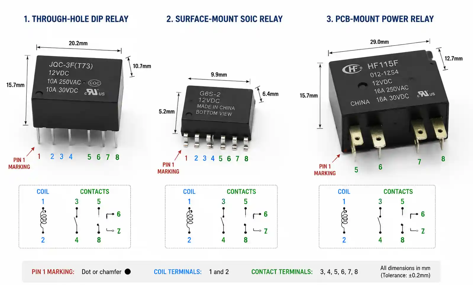
The additional pins enable design flexibility not available in simpler relay configurations. In dual-coil designs, separate energize and de-energize coils allow for bidirectional magnetic flux control, which is essential in latching relay applications where the relay maintains its state without continuous power. In DPDT configurations, the 8-pin arrangement accommodates two independent sets of changeover contacts, enabling simultaneous switching of two separate circuits with a single coil activation.
Engineers should consider 8-pin relays when the application requires any of the following: isolation between two independent circuits that must switch simultaneously, latching functionality to minimize power consumption in battery-operated devices, bidirectional motor control without external H-bridge circuits, or redundant contact paths for safety-critical applications. Common use cases include automotive body control modules, industrial process controllers, HVAC zone control systems, and medical equipment requiring fail-safe operation.
2. Key Technical Parameters Explained
Understanding the datasheet parameters of an 8-pin relay is critical for proper selection and reliable operation. The following parameters directly impact switching performance, thermal management, and longevity.
Coil Specifications: The coil voltage and resistance determine the drive requirements and power dissipation. Standard coil voltages include 5V, 12V, 24V, and 48V DC, with typical coil resistance ranging from 50Ω to 1kΩ. The must-operate voltage (typically 70-80% of nominal) and must-release voltage (typically 5-10% of nominal) define the reliable switching thresholds. Pick-up time and drop-out time, usually in the 5-15ms range, affect switching speed and bounce characteristics.
Contact Ratings: The maximum switching current and voltage ratings must be derated based on load type. Resistive loads can typically be switched at full rated current, but inductive loads (motors, solenoids) may require derating to 30-50% of the resistive rating due to back-EMF transients. Capacitive loads (power supplies, LED drivers) can cause high inrush currents that stress contact surfaces. The contact resistance, typically below 100mΩ when new, increases with operational cycles and can affect low-voltage or precision applications.
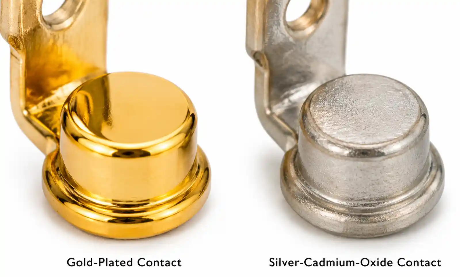
Electrical Life and Mechanical Life: Mechanical life represents cycles with no load applied, typically ranging from 10 million to 100 million operations. Electrical life under full load is significantly shorter—often 100,000 to 500,000 operations depending on contact material and load characteristics. Gold-plated contacts offer superior low-level switching performance but limited high-current capability, while silver-cadmium-oxide or silver-nickel contacts handle higher currents but require higher minimum loads to maintain clean contact surfaces.
Isolation Voltage and Creepage Distance: The dielectric withstand voltage between coil and contacts, typically 1kV to 5kV AC, determines the safety margin in applications with voltage transients. Creepage and clearance distances, governed by IEC 60664 or UL 60950 standards, define minimum spacing for pollution degree and overvoltage category. For industrial environments (Pollution Degree 2) at 300V working voltage, minimum creepage is typically 3.2mm.
Operating Temperature Range: Automotive-grade relays qualified to AEC-Q200 operate from -40°C to +125°C, while industrial-grade components may be limited to -25°C to +85°C. Coil resistance and contact materials both exhibit temperature coefficients that affect performance at temperature extremes.
3. 8-Pin vs 5-Pin vs 4-Pin Relay: Configuration Comparison
Choosing between relay pin configurations depends on switching requirements, control complexity, and cost constraints. The table below compares the functional differences.
| Parameter | 4-Pin SPST | 5-Pin SPDT | 8-Pin DPDT/Dual-Coil |
|---|---|---|---|
| Contact Configuration | Single NO or NC | 1 Common, 1 NO, 1 NC | 2 independent changeover sets OR latching |
| Coil Terminals | 2 | 2 | 2 (or 4 for dual-coil latching) |
| Typical Switching Voltage | Up to 250V AC | Up to 250V AC | Up to 250V AC per pole |
| Typical Switching Current | 10-30A | 10-30A | 5-15A per pole |
| Simultaneous Circuit Switching | No | No | Yes (DPDT) |
| Latching Capability | No | No | Yes (dual-coil variants) |
| PCB Footprint | Smallest | Small | Medium to Large |
| Cost Relative | Lowest | Low | Medium to High |
| Typical Applications | Power on/off | Changeover, direction control | Dual circuit isolation, latching |
For applications requiring only simple on/off control, a 4-pin SPST relay offers the smallest footprint and lowest cost. When a single circuit needs changeover functionality—such as reversing polarity or selecting between two signal paths—a 5-pin SPDT relay is sufficient. The 8-pin configuration becomes necessary when you need to switch two electrically isolated circuits simultaneously with precise timing, implement latching functionality for power savings, or achieve redundant contact paths for functional safety compliance.
In motor control applications, an 8-pin DPDT relay can replace two separate SPDT relays, reducing board space and ensuring synchronous contact closure. In latching applications, the dual-coil 8-pin relay eliminates continuous coil power consumption, which is critical for battery-powered equipment where standby current must be minimized.
4. How to Select the Right 8-Pin Relay for Your Application
Proper relay selection follows a systematic methodology that prioritizes application-specific requirements.
Step 1: Define Load Characteristics: Identify whether the load is resistive, inductive, capacitive, or a combination. Measure or estimate the steady-state current, inrush current, and any voltage transients. For inductive loads such as solenoid valves or motor windings, calculate the L/R time constant to understand back-EMF magnitude. For capacitive loads like switch-mode power supplies, determine the peak inrush current during the first half-cycle.
Step 2: Determine Contact Configuration Needs: Decide if you need DPDT switching for dual circuits, latching for power savings, or standard single-pole operation. For safety-critical applications, assess whether redundant contacts (force-guided contacts per IEC 61810-3) are required. In signal routing applications, evaluate whether gold-plated contacts are necessary for low-level switching (typically below 10mA at 6V).
Step 3: Specify Coil Drive Requirements: Match the coil voltage to your control circuit supply rail. If driving directly from a microcontroller, ensure the GPIO driver can sink sufficient current (typically 30-80mA for small signal relays, up to 200mA for power relays). For high-side drive, select relays with appropriate coil polarity flexibility. Calculate coil power dissipation and ensure it remains within thermal limits in your enclosure environment.
Step 4: Evaluate Environmental Requirements: For automotive applications, specify AEC-Q200 qualification and verify operating temperature, vibration resistance (typically 10G), and shock tolerance. For industrial environments, check IP rating requirements and confirm compatibility with the expected pollution degree. Medical applications may require additional isolation and leakage current limits per IEC 60601-1.
| Application Scenario | Recommended 8-Pin Relay Type | Key Parameter Priority | Typical Part Examples |
|---|---|---|---|
| Automotive body control | DPDT, AEC-Q200, -40°C to +125°C | Temperature range, vibration, EMC | Panasonic ALD, TE Connectivity V23234 |
| Industrial PLC output | DPDT, PCB mount, 5A per pole | Electrical life, surge immunity | Omron G2R-2, Finder 40.52 |
| Battery-powered IoT device | Latching dual-coil, low coil power | Power consumption, mechanical life | Fujitsu FTR-K3, Panasonic TQ2SA |
| Medical isolation switching | DPDT, reinforced insulation, gold contacts | Isolation voltage, low-level switching | TE Connectivity IM, Axicom IMO |
| HVAC zone control | DPDT, 10A resistive rating | Contact life, ambient temperature | Hongfa HF46F, Song Chuan 833H |
The table above provides application-specific guidance, but always validate final selection against actual datasheet specifications. Pay particular attention to derating curves for temperature, voltage, and load type.
Step 5: Design for Thermal Management: Calculate worst-case power dissipation including both coil power and contact I²R losses. For surface-mount relays, ensure PCB copper area provides adequate heat sinking. Typical thermal resistance from relay case to ambient is 30-50°C/W for small signal relays, requiring careful consideration in high-density designs.
5. Design Considerations and Common Pitfalls
Even with correct relay selection, PCB layout and circuit design choices significantly impact reliability.
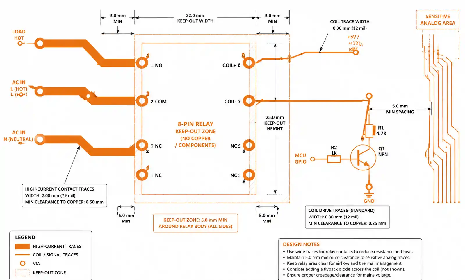
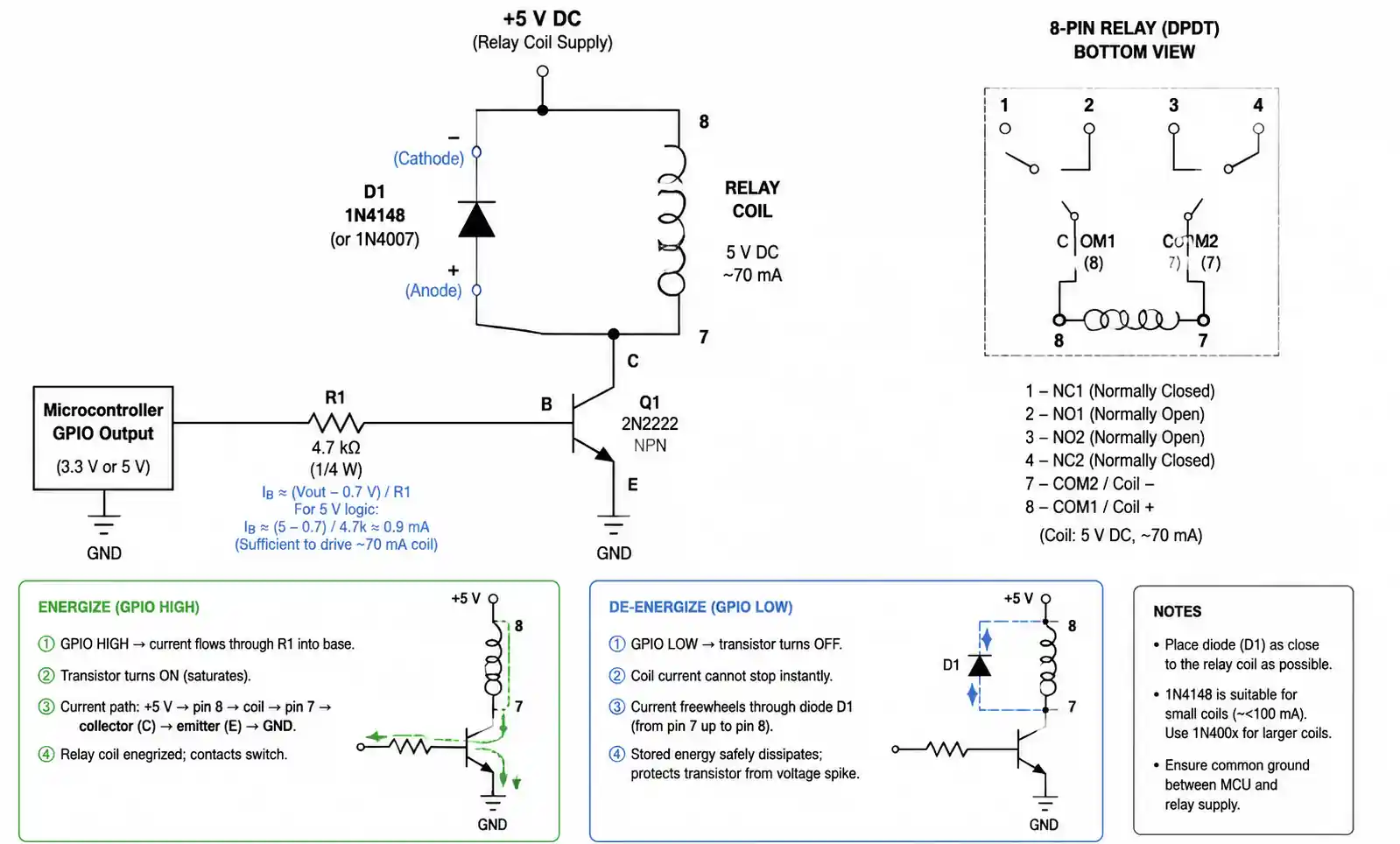
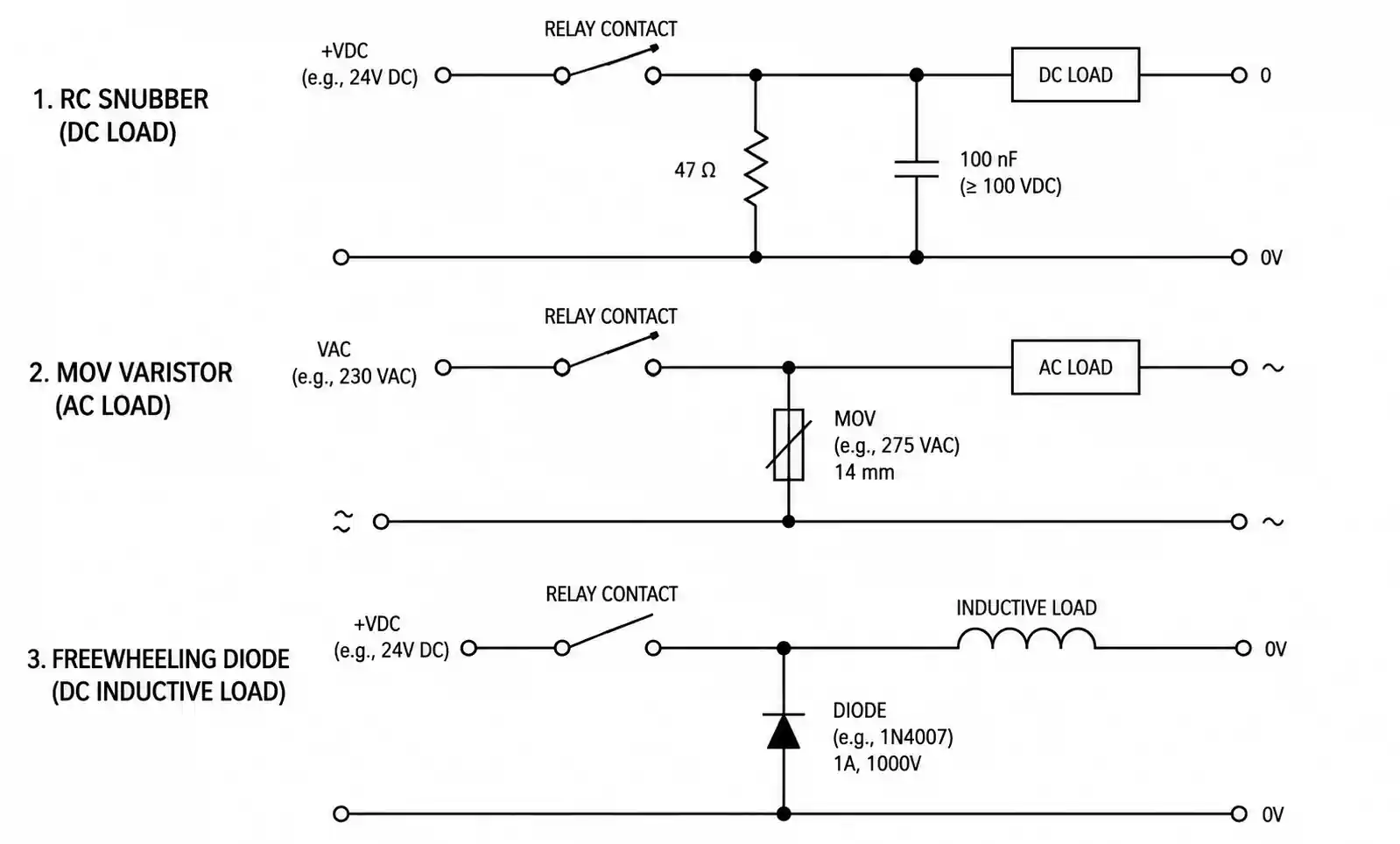
Coil Drive Circuit Design: Always include a flyback diode across relay coils to suppress inductive kickback when switching off. For logic-level coil drive, use a transistor buffer rather than driving directly from GPIO pins—GPIO current limits and voltage drop can cause marginal operation. When driving multiple relays, ensure the power supply can handle simultaneous inrush current during all-on conditions. Adding a small RC snubber (100Ω + 100nF) across the coil can further reduce EMI during switching.
Contact Arc Suppression: For DC inductive loads, arc suppression across the contacts is essential to prevent contact erosion. A simple RC snubber (47Ω + 100nF rated for peak voltage) across the switched contacts reduces arc energy. For AC switching, MOV varistors provide transient protection. In high-reliability applications, consider solid-state relay alternatives for loads that switch frequently under high stress.
PCB Layout Mistakes: The most common error is placing the coil drive traces too close to sensitive analog signals—relay switching generates magnetic fields and conducted EMI that can couple into adjacent circuits. Maintain at least 5mm spacing between relay coils and precision analog traces. Route high-current contact traces with adequate copper width (minimum 20 mils per amp for external layers) and keep trace lengths short to minimize voltage drop and EMI radiation.
Mechanical Considerations: Ensure the relay is properly secured to the PCB. Through-hole relays should be wave-soldered with sufficient preheat to avoid thermal shock. Surface-mount relays require carefully controlled reflow profiles—exceeding the peak temperature or time-above-liquidus specified in the datasheet can damage the internal seal or contact springs. In high-vibration environments, consider conformal coating or potting to prevent contact chatter.
Contact Bounce and Timing: Relay contacts inherently bounce for 1-10ms during closure, which can cause false triggering in digital logic or microcontroller inputs. If monitoring contact state, implement software debouncing or hardware RC filtering. When sequencing multiple relays, allow at least 50ms between operations to ensure stable contact closure before applying load current.
Failure Modes to Anticipate: Contact welding occurs when switching currents exceed the contact's interrupting capability, particularly with inductive or capacitive loads. Coil overheating from excessive duty cycle or ambient temperature can cause insulation failure or reduced magnetic force. Contact contamination from organic vapors or dust reduces reliability in low-level switching applications—hermetically sealed relays are recommended for harsh environments.
6. Supply Chain and Sourcing Considerations
Relay availability, lead times, and quality assurance are critical factors in production planning.
Lead Times and Inventory Management: Standard catalog relays from major manufacturers (Omron, TE Connectivity, Panasonic, Finder) typically have 8-16 week lead times for volume orders, with smaller quantities available through distributors like Digi-Key, Mouser, and Newark. During component shortages, lead times can extend to 26+ weeks. Maintain safety stock of at least 3 months' consumption for production-critical relays, and identify second-source alternatives early in the design phase.
Quality and Counterfeit Risk: Relays are frequent targets for counterfeiting due to their high value and external appearance similarity. Always purchase from authorized distributors or directly from manufacturers. Verify date codes, packaging, and labeling against manufacturer specifications. For aerospace or medical applications, require Certificate of Conformance (CoC) and lot traceability. Be cautious of unusually low pricing or offers from unknown suppliers—counterfeit relays may have inferior contact materials or inadequate isolation.
| Sourcing Factor | Recommended Practice | Risk Mitigation |
|---|---|---|
| Supplier qualification | Use only authorized distributors | Request distributor authorization letters |
| Lead time management | Maintain 3-6 month buffer stock | Identify second sources during design |
| Component authentication | Verify date codes and packaging | Request CoC for critical applications |
| Obsolescence planning | Monitor manufacturer PCN notices | Design with pin-compatible alternates |
| Cost optimization | Compare total cost including logistics | Consider regional sourcing for high volume |
Obsolescence and Lifecycle Management: Monitor Product Change Notices (PCN) and End-of-Life (EOL) announcements from manufacturers. When a relay goes EOL, identify pin-compatible alternatives with equivalent or superior specifications. In some cases, socket-mounted relays provide easier retrofitting compared to PCB-soldered types. Design with standard pinouts when possible to maximize alternate source availability.
Regional Sourcing Strategies: For high-volume production in Asia, consider locally manufactured relays from Hongfa, Song Chuan, or Fujitsu that meet international standards but offer shorter lead times and lower logistics costs. For North American or European production, TE Connectivity and Finder offer local inventory and technical support. Always validate locally-sourced relays against your specifications with incoming inspection or qualification testing.
7. FAQ
What is the main advantage of an 8-pin relay over a 5-pin relay?
An 8-pin relay provides either dual-pole switching capability (DPDT) to control two isolated circuits simultaneously, or dual-coil latching functionality to maintain state without continuous power. This enables applications like simultaneous phase and neutral switching, redundant contact paths for safety systems, or ultra-low standby current in battery-operated devices—none of which are possible with a single-pole 5-pin SPDT relay.
Can I drive an 8-pin relay coil directly from a microcontroller GPIO?
Not recommended. Most relay coils require 30-200mA, exceeding typical GPIO current limits of 4-25mA. Use a transistor buffer (NPN or N-channel MOSFET) with appropriate base/gate resistor, and include a flyback diode across the coil. This protects the microcontroller from inductive kickback and ensures reliable relay operation across temperature and supply voltage variations.
How do I calculate the required contact rating for an inductive load?
Derate the resistive contact rating by 50-70% for inductive loads. For example, a relay rated 10A resistive should be limited to 3-5A for motor or solenoid loads. Check the datasheet for the L/R time constant limit—typically 7ms for general-purpose relays. If your load exceeds this, add arc suppression across the contacts or select a relay with higher inductive rating.
What is the difference between mechanical life and electrical life?
Mechanical life (typically 10-100 million operations) measures relay endurance with no load current, testing only the mechanical wear of springs and bearings. Electrical life (typically 100,000-500,000 operations) measures endurance under full rated load, where contact arcing and erosion dominate. Always design for electrical life in your application, as it is far shorter than mechanical life.
Are there AEC-Q200 qualified 8-pin relays for automotive applications?
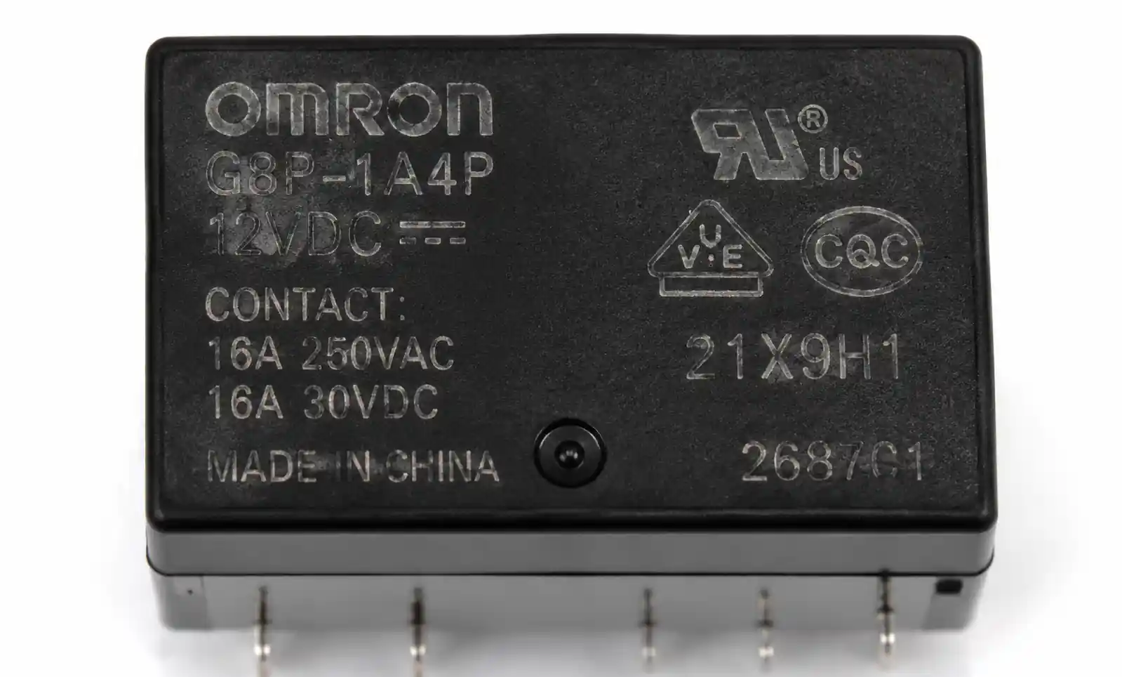
Yes. Major manufacturers including Panasonic (ALD series), TE Connectivity (V23234 series), and Omron (G8P series) offer AEC-Q200 qualified 8-pin relays rated from -40°C to +125°C. These components pass additional qualification tests for vibration, shock, thermal cycling, and moisture resistance required for automotive underhood and body control applications. Verify qualification status in the datasheet and request automotive-grade part numbers.
How do I prevent contact bounce from causing false triggering?
Implement software debouncing in firmware by sampling contact state every 5-10ms and requiring consistent readings for 20-50ms before accepting a state change. Alternatively, add hardware debouncing with an RC filter (10kΩ + 100nF) and Schmitt trigger buffer on the contact sense line. For critical timing applications, consider solid-state relays which have no mechanical bounce.
What testing should I perform to validate relay selection?
Minimum validation includes: continuous operation at maximum rated load and temperature for 1000 cycles, cold start testing at minimum operating temperature, voltage margining of coil drive at ±10%, contact resistance measurement before and after life testing, and dielectric withstand testing per datasheet specifications. For safety-critical applications, also perform FMEA and validate forced-contact monitoring if implemented.
Can I use an 8-pin relay for AC power switching?
Yes, but verify the relay is specifically rated for AC switching. AC contact ratings differ from DC due to zero-crossing behavior and arc extinction characteristics. Check the datasheet for AC voltage and current ratings, typically specified at 50/60Hz. For high inrush loads like transformers or motors, apply the same derating as for DC inductive loads. UL or VDE safety approvals indicate suitability for AC mains applications.
8. Conclusion and Next Steps
Selecting the right 8-pin relay requires balancing contact configuration, load characteristics, environmental requirements, and supply chain constraints. If your application demands dual-circuit isolation, latching functionality, or force-guided contacts for safety compliance, an 8-pin relay provides capabilities unavailable in simpler configurations. The key decision points are: contact configuration (DPDT vs latching), electrical life under your specific load type, coil drive compatibility with your control circuit, and environmental qualification appropriate to your application.
Before finalizing component selection, validate the following: contact current rating with appropriate derating for load type, coil drive circuit design including flyback suppression, thermal management at worst-case ambient temperature, PCB layout including trace sizing and isolation spacing, and supply chain viability including lead times and second-source options. Download complete datasheets for candidate relays and review application notes from the manufacturer addressing your specific application scenario.
For high-reliability or safety-critical applications, consider engaging with the manufacturer's Field Application Engineer (FAE) team for design review and qualification support. If your design requires customization—such as specific coil voltage, contact plating, or mounting orientation—lead times may extend significantly, so initiate discussions early in the design cycle.