




Battery Management IC Selection for Lithium-Ion Applications
Selecting the right battery management IC (BMS IC) directly impacts the safety, lifespan, and performance of lithium-ion battery systems. In applications ranging from electric vehicles to portable medical devices, a poorly chosen BMS IC can lead to premature cell degradation, thermal runaway, or catastrophic field failures. With lithium-ion cells operating within narrow voltage windows—typically 2.5V to 4.2V per cell—and requiring precise charge control, the BMS IC serves as the critical electronic safeguard that prevents overcharge, overdischarge, and thermal events while maximizing usable capacity.
At Hitop Tech Limited, we support engineering teams in sourcing BMS ICs and related power management components through our procurement services, ensuring reliable supply chains for battery-powered product development.
Table of Contents
- Core BMS IC Functions and Architecture
- Protection Features: Overvoltage, Undervoltage, and Overcurrent
- Cell Balancing Methods: Passive vs Active
- State Estimation: SOC and SOH Algorithms
- Charging Algorithms and Multi-Cell Configurations
- Safety Standards and Certification Requirements
- FAQ
- Conclusion
1. Core BMS IC Functions and Architecture
A battery management IC integrates multiple functions into a single chip or chipset: voltage monitoring, current sensing, temperature measurement, protection circuitry, and communication interfaces. Understanding these building blocks helps engineers match IC capabilities to application requirements rather than over-specifying or under-protecting.
Voltage Monitoring Precision
Modern BMS ICs measure individual cell voltages with 12-bit to 16-bit ADC resolution, translating to ±5mV to ±10mV accuracy across the operating range. For a 4.2V lithium-ion cell, ±10mV represents 0.24% error—sufficient for most applications but critical for state-of-charge estimation accuracy. High-precision designs targeting automotive or aerospace applica tions specify ±3mV or better, enabling SOC estimation within 2-3% error bands.
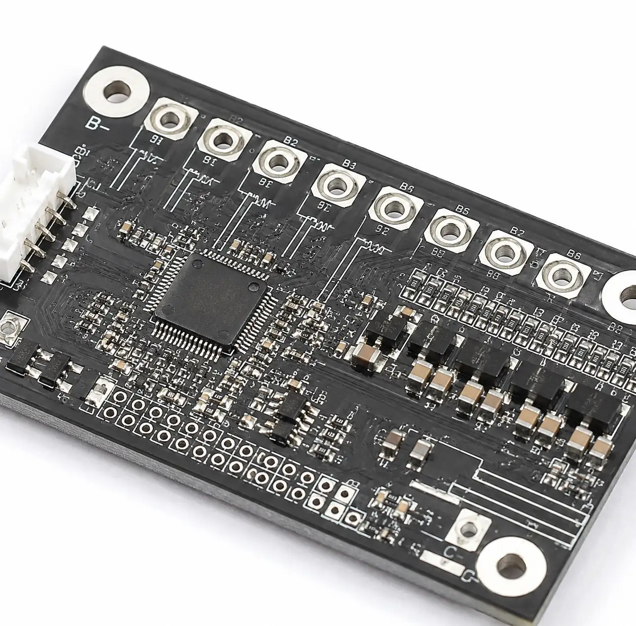
Multi-cell BMS IC voltage monitoring architecture showing differential measurement channels
The voltage monitoring architecture varies by cell count. Single-cell ICs integrate directly with one lithium cell (3.7V nominal), while multi-cell ICs stack monitoring channels to support 3S to 16S configurations (11.1V to 59.2V nominal). Each additional cell requires differential voltage measurement between adjacent nodes, increasing pin count and internal complexity. For packs beyond 16 cells, daisy-chained or modular BMS architectures distribute monitoring across multiple ICs.
Current Sensing and Coulomb Counting
Accurate current measurement enables precise state-of-charge tracking through coulomb counting—integrating charge and discharge current over time. BMS ICs typically measure pack current through a low-side or high-side sense resistor (1mΩ to 10mΩ), with the IC amplifying the small voltage drop across this resistor. A 10A current through a 5mΩ resistor produces only 50mV, requiring high common-mode rejection and low offset voltage in the sense amplifier.
| BMS IC Specification | Entry-Level (Portable Electronics) | Mid-Range (Power Tools, ESS) | Automotive-Grade (EV, HEV) |
|---|---|---|---|
| Voltage accuracy | ±10mV to ±15mV | ±5mV to ±10mV | ±3mV to ±5mV |
| Current sense accuracy | ±2% to ±3% | ±1% to ±2% | ±0.5% to ±1% |
| Cell count support | 1S to 4S | 3S to 13S | 6S to 16S (modular to 400S+) |
| ADC resolution | 12-bit | 14-bit to 16-bit | 16-bit to 18-bit |
| Temperature sensors | 1 external thermistor | 2-4 external thermistors | 4-8 thermistors + internal sensor |
| Balancing current | 50mA to 100mA passive | 100mA to 200mA passive | 200mA passive or active transfer |
Communication Interfaces
BMS ICs communicate battery status to host microcontrollers or system processors through I²C, SPI, UART, or CAN interfaces. I²C dominates in portable and low-speed applications (up to 400kHz), while automotive designs increasingly adopt CAN or CAN-FD for noise immunity and standardized protocols. High-voltage EV battery packs often use isolated communication—either optocouplers or isolated CAN transceivers—to protect low-voltage control circuitry from high-voltage battery potentials.
2. Protection Features: Overvoltage, Undervoltage, and Overcurrent
Protection circuits prevent destructive operating conditions that can trigger thermal runaway or permanent cell damage. BMS ICs implement these protections through hardware comparators that respond within microseconds, independent of microcontroller firmware execution.
Overvoltage Protection (OVP)
Lithium-ion cells suffer irreversible damage when charged beyond their maximum voltage—typically 4.20V to 4.35V depending on chemistry. Overcharging causes lithium plating on the anode, reducing capacity and creating internal dendrites that can pierce the separator and cause short circuits. BMS ICs set OVP thresholds 50mV to 100mV below the absolute maximum voltage, with typical thresholds at 4.25V to 4.30V for standard cells.
When any cell exceeds the OVP threshold, the BMS IC immediately opens the charge path MOSFET, disconnecting the charger. The protection remains active until cell voltage drops below a release threshold (typically 100mV below the OVP trip point), implementing hysteresis to prevent chattering at the threshold voltage.
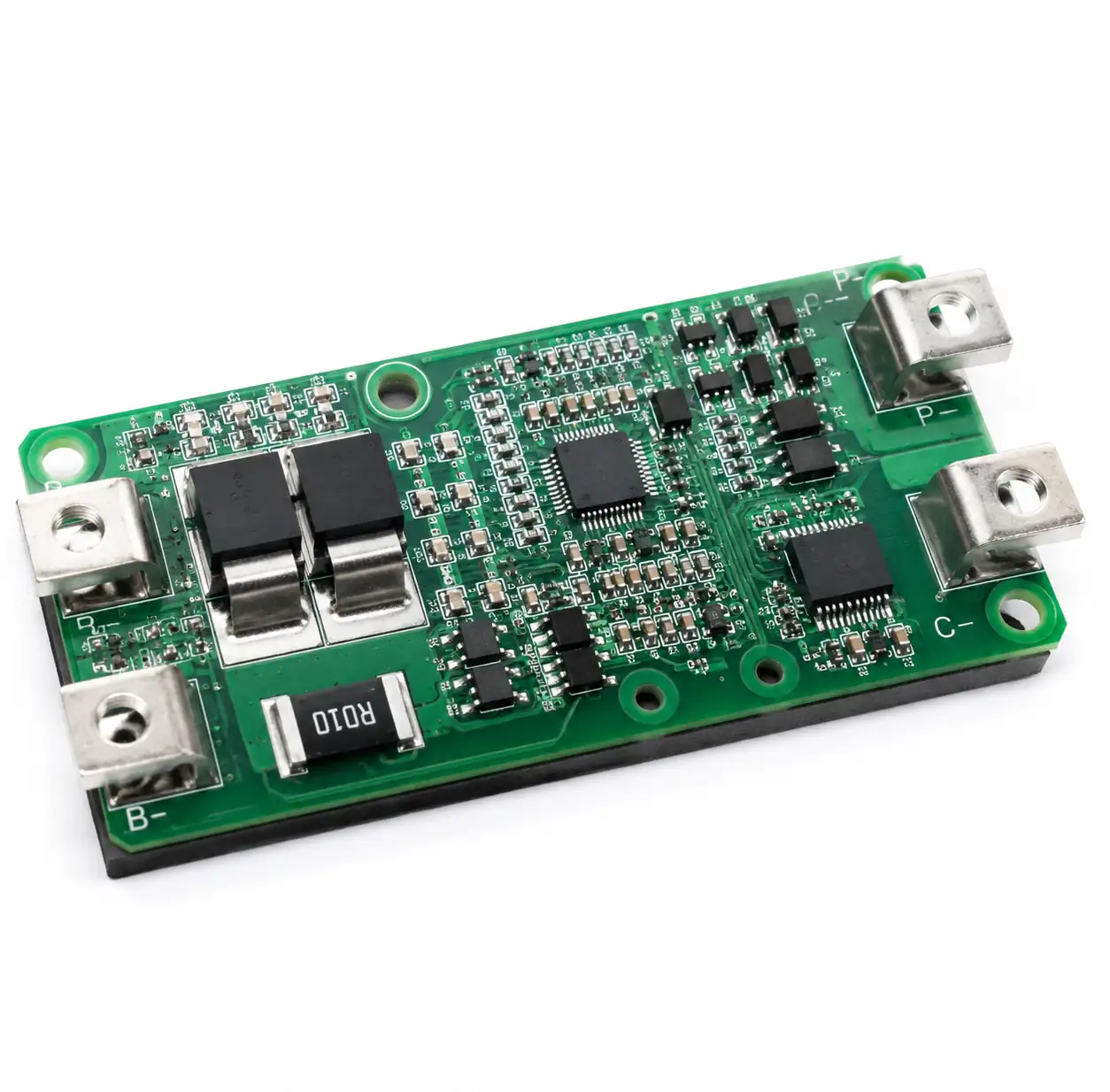 Charge and discharge MOSFET protection circuit in BMS implementation
Undervoltage Protection (UVP)
Discharging lithium-ion cells below 2.5V to 2.7V causes copper dissolution from current collectors and permanent capacity loss. Deep discharge to 2.0V or lower often renders cells unrecoverable. UVP thresholds typically sit at 2.5V to 2.8V, with 100mV to 200mV hysteresis for release.
Overcurrent Protection (OCP) and Short Circuit Protection (SCP)
Overcurrent events—whether from excessive load or external short circuits—generate resistive heating that can trigger thermal runaway within seconds. BMS ICs implement two-stage current protection: OCP for sustained overcurrent (1.5× to 2× rated current for 100ms to 1s) and SCP for severe faults (5× to 10× rated current for 100μs to 1ms).
The sense resistor and discharge MOSFET RDS(on) create a voltage proportional to current. When this voltage exceeds the OCP threshold, the BMS opens the discharge MOSFET. SCP responds faster, typically through dedicated comparators that bypass digital filtering. The protection release conditions vary by design—some require manual reset, while others auto-retry after a delay period.
3. Cell Balancing Methods: Passive vs Active
Cell-to-cell voltage variations emerge from manufacturing tolerances, temperature gradients, and aging differences. Without balancing, the weakest cell limits pack capacity—when one cell reaches its voltage limit during charge or discharge, the entire pack must stop even if other cells have remaining capacity. Balancing redistributes charge to maximize usable pack energy.
Passive Balancing Architecture
Passive balancing dissipates excess energy from higher-voltage cells as heat through bypass resistors. When cell voltage differences exceed a threshold (typically 30mV to 50mV), the BMS IC activates a MOSFET that shunts current through a resistor parallel to the high cell. Balancing currents range from 50mA to 200mA, limited by power dissipation and thermal management.
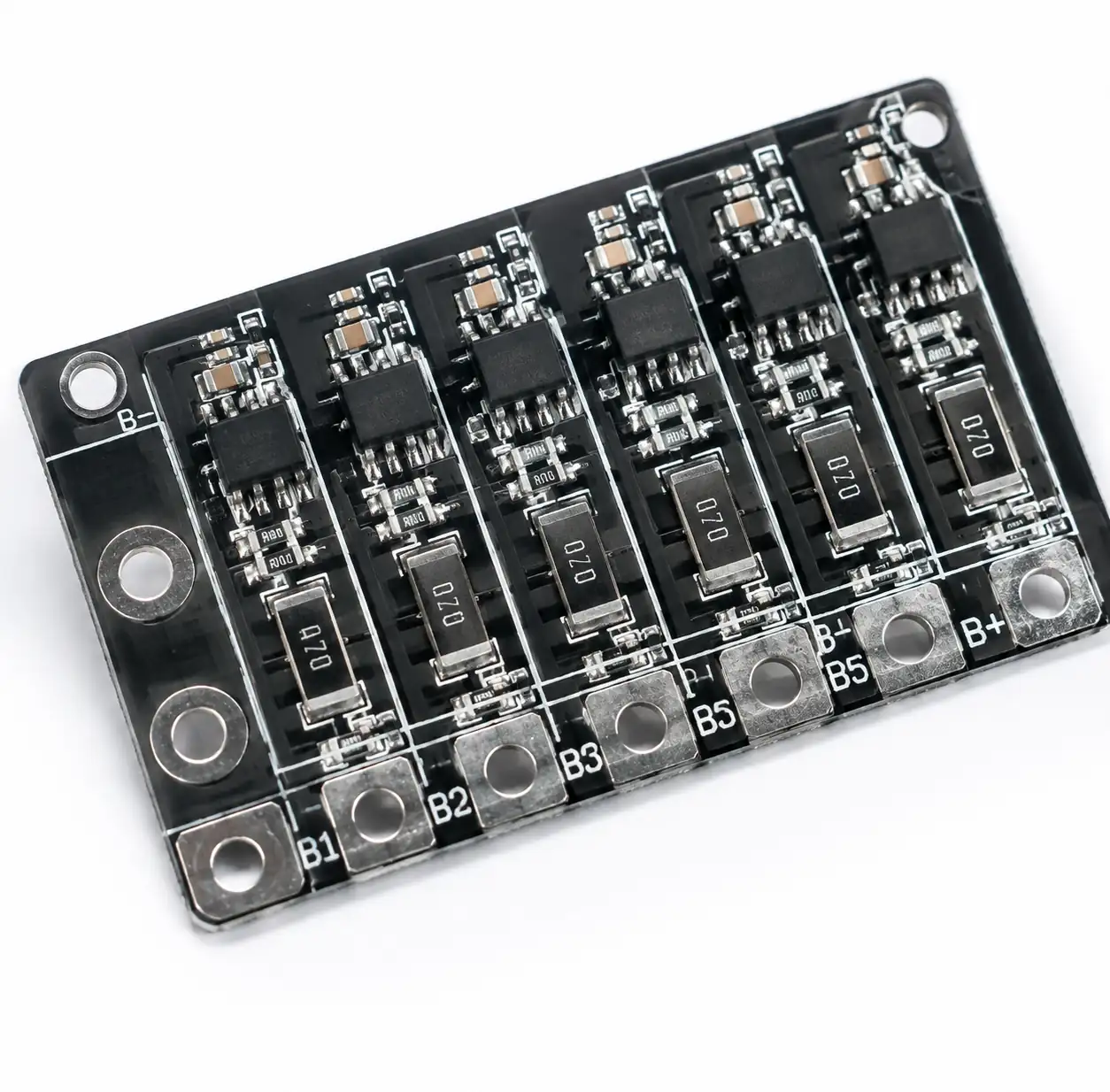 Passive cell balancing circuit showing bypass resistors and MOSFETs
The primary advantage of passive balancing is simplicity and low cost—requiring only MOSFETs and resistors integrated into the BMS IC or as external components. The disadvantage is energy waste: all balancing energy converts to heat rather than redistributing to weaker cells. For a 10Ah pack with 100mAh imbalance per cell, passive balancing at 100mA requires one hour per cell and wastes 3.7Wh to 4.2Wh per cell as heat.
Active Balancing Topologies
Active balancing transfers energy between cells rather than dissipating it, improving efficiency to 70% to 95% depending on topology. Common active balancing methods include capacitor shuttling, inductor-based buck-boost converters, and transformer-coupled energy transfer.
Capacitor shuttling connects a flying capacitor alternately between adjacent cells, transferring charge from higher voltage to lower voltage cells. This method works well for small voltage differences and adjacent cell balancing but struggles with large imbalances or non-adjacent cell transfer. Balancing current reaches 500mA to 2A, significantly faster than passive methods.
| Balancing Method | Typical Current | Energy Efficiency | Cost | Best Applications |
|---|---|---|---|---|
| Passive (resistor bleed) | 50mA to 200mA | 0% (all waste heat) | Low ($0.50 to $2 per cell) | Portable electronics, power tools, small ESS |
| Active capacitor shuttle | 500mA to 2A | 70% to 85% | Medium ($2 to $5 per cell) | Mid-size EV, ESS (2kWh to 10kWh) |
| Active inductor-based | 1A to 5A | 85% to 95% | High ($5 to $15 per cell) | Large EV, grid ESS (>10kWh) |
| Active transformer-coupled | 2A to 10A | 90% to 95% | High ($10 to $20 per cell) | High-power EV, utility ESS (>50kWh) |
Balancing time is critical for operational efficiency. A 100Ah EV battery pack with 1Ah cell imbalance requires 10 hours of 100mA passive balancing but only 2 hours with 500mA active balancing. For fleets with daily charging cycles, faster balancing directly impacts vehicle availability.
4. State Estimation: SOC and SOH Algorithms
Accurate state-of-charge (SOC) and state-of-health (SOH) estimation enables effective battery utilization and predictive maintenance. Unlike fuel tanks with direct level sensing, batteries require indirect estimation through voltage, current, and temperature measurements combined with electrochemical models.
Coulomb Counting and Voltage-Based SOC
The most common SOC method combines coulomb counting with open-circuit voltage (OCV) correlation. Coulomb counting integrates charge and discharge current over time, calculating SOC as:
SOC = SOC₀ + (1/Capacity) × ∫(I dt)
where SOC₀ is initial state, I is pack current (positive for charge, negative for discharge), and Capacity is the cell's amp-hour rating. This method provides good dynamic response but accumulates error from current sensor inaccuracy and capacity uncertainty.
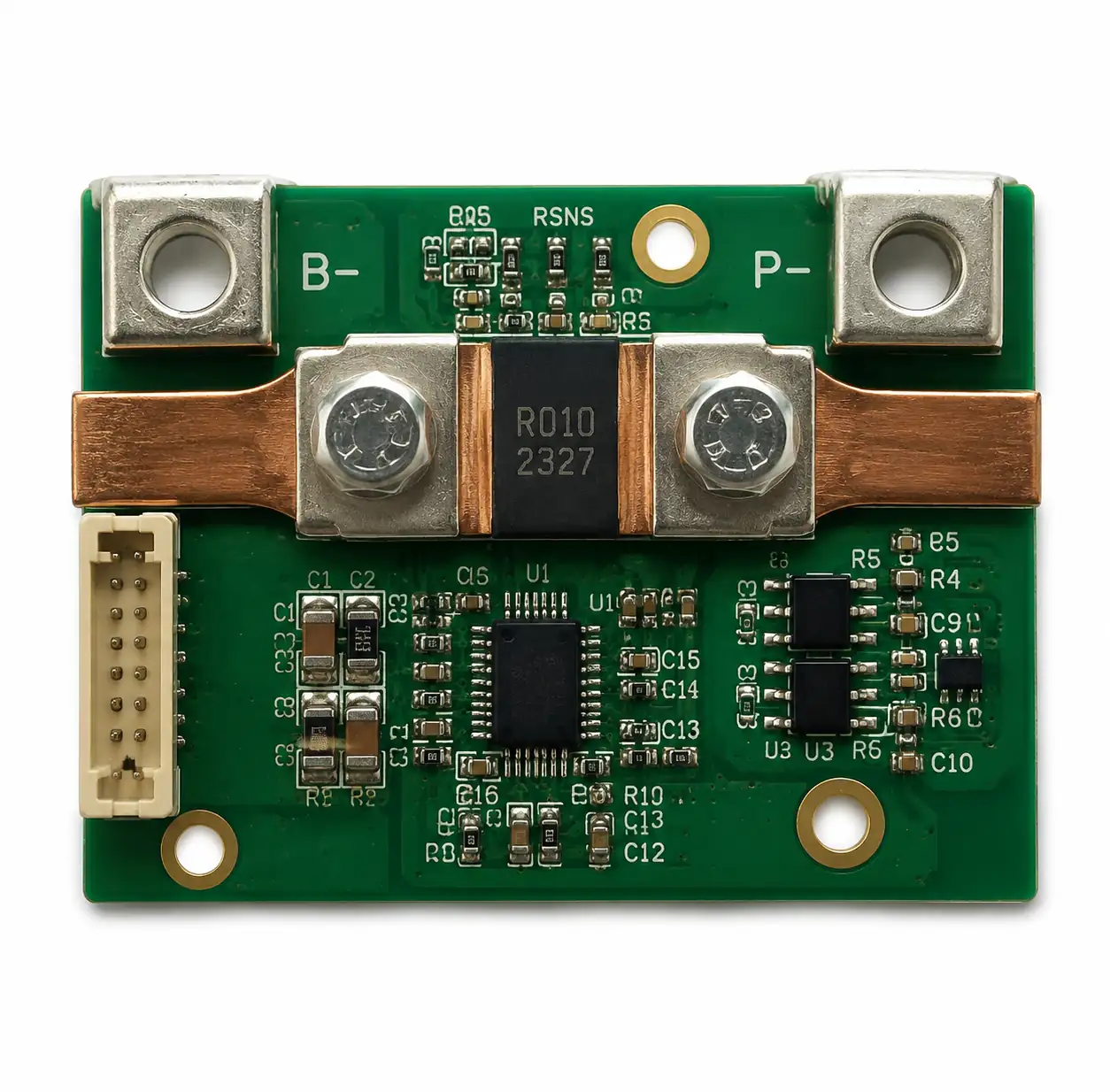 Current sense resistor and amplifier circuit for coulomb counting
Voltage-based SOC correlates terminal voltage to SOC using lookup tables derived from cell characterization. However, lithium-ion voltage remains relatively flat through the middle 20% to 80% SOC range, making precise estimation difficult. Voltage-based methods work best at the extremes (0-20% and 80-100% SOC) where voltage changes more rapidly. Modern BMS ICs combine both methods: coulomb counting for dynamic tracking with periodic OCV calibration during rest periods.
State-of-Health Estimation
SOH quantifies battery degradation relative to beginning-of-life specifications, typically expressed as capacity fade and resistance growth. A battery with 20% capacity loss exhibits 80% SOH. Accurate SOH estimation enables predictive maintenance and warranty compliance verification.
5. Charging Algorithms and Multi-Cell Configurations
Lithium-ion charging requires precise voltage and current control to maximize cell lifespan while minimizing charge time. The standard CC-CV (constant current-constant voltage) algorithm charges at maximum current until reaching voltage limit, then holds voltage constant while current tapers.
CC-CV Charging Profile
During the constant current phase, the BMS IC or external charger supplies rated charge current (typically 0.5C to 1C) until any cell reaches 4.2V. For a multi-cell pack, the highest cell dictates the transition to constant voltage mode. During CV phase, voltage remains at 4.2V while current gradually decreases. Charging terminates when current drops below C/10 to C/20, indicating the cell is >95% charged.
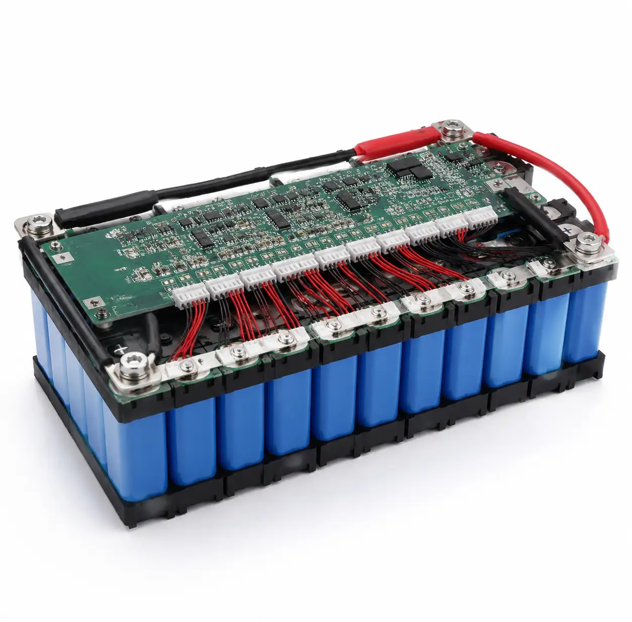 Lithium-ion battery pack assembly with integrated BMS circuit board
Fast charging modifies this profile with multi-stage current tapers or dynamic voltage limits based on cell temperature. A 1C charge rate (full charge in one hour) is standard, while fast charging pushes to 2C or 3C during the CC phase. However, charging above 1C accelerates degradation—particularly lithium plating—and requires active thermal management to maintain cell temperature below 45°C.
Multi-Cell Series-Parallel Configurations
Battery packs combine cells in series (S) to achieve voltage and parallel (P) to achieve capacity. A 12S4P pack connects 12 cells in series for 44.4V nominal (12 × 3.7V) and 4 cells in parallel per series group for 4× capacity. The BMS IC must monitor all 12 series groups, with each group's 4 parallel cells typically treated as a single monitored unit.
6. Safety Standards and Certification Requirements
Battery safety regulations vary by application and region but share common requirements for protection against thermal runaway, overcharge, and mechanical abuse. Compliance with these standards is mandatory for market access and product liability mitigation.
Key Safety Standards
UL 2054 and UL 1642 cover battery cells and packs for portable applications in North America, specifying tests for overcharge, short circuit, impact, and thermal exposure. IEC 62133 provides equivalent international standards for portable batteries. Both require BMS protection circuits that prevent overcharge beyond 4.3V to 4.4V and overdischarge below 2.5V.
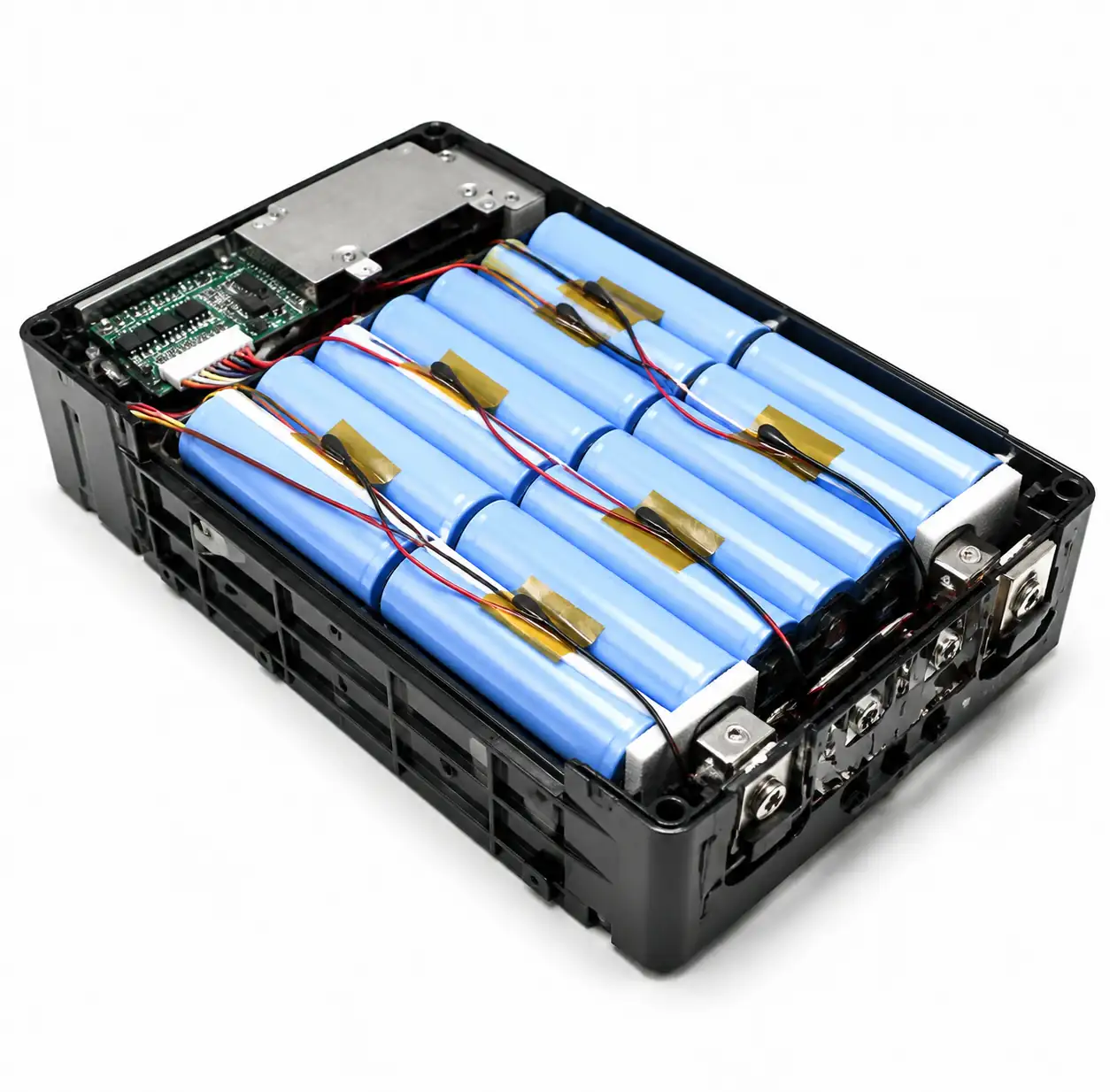 Temperature sensor placement on battery pack for thermal monitoring
UN 38.3 governs lithium battery transport via air, sea, and ground, requiring testing for altitude simulation, thermal cycling, vibration, shock, external short circuit, impact, and overcharge. Products failing UN 38.3 testing cannot be legally shipped through most commercial carriers, severely limiting market reach.
Functional Safety and Redundancy
Safety-critical BMS designs implement redundant protection—dual-level overvoltage comparators, independent charge and discharge disconnect MOSFETs, and fail-safe defaults that open disconnect switches on any fault detection. If the primary microcontroller fails or locks up, hardware comparators continue monitoring and protection without firmware intervention.
7. FAQ
What is the difference between a BMS IC and a complete BMS circuit board?
A BMS IC is the integrated circuit chip that performs voltage monitoring, current sensing, and protection logic. A complete BMS circuit board includes the BMS IC plus external components: MOSFETs for charge/discharge disconnect, sense resistors, balancing resistors, temperature sensors, communication interfaces, and connectors. The IC provides the intelligence and precision measurements, while the board integrates these into a functional system matched to specific battery pack voltage, current, and mechanical requirements.
How does temperature affect BMS IC accuracy and protection thresholds?
Lithium-ion cell voltage varies -2mV/°C to -4mV/°C, meaning a cell at 4.20V at 25°C may read 4.16V at 45°C from temperature coefficient alone. BMS ICs with temperature-compensated voltage references maintain ±5mV accuracy across -40°C to +85°C, but protection thresholds may require adjustment for temperature. Some advanced BMS ICs implement temperature-dependent OVP/UVP thresholds that tighten limits at temperature extremes to prevent accelerated degradation. Current sensor accuracy also degrades with temperature unless calibrated, affecting coulomb counting precision. Always verify BMS specifications at worst-case operating temperatures, not just 25°C lab conditions.
What is the typical quiescent current for BMS ICs in standby mode?
Entry-level BMS ICs consume 10μA to 50μA in standby, draining a 3000mAh cell in roughly 6 to 25 years if no self-discharge occurred. Mid-range ICs with more features draw 50μA to 200μA (1.5 to 6 years). Automotive-grade ICs with CAN communication and continuous monitoring may consume 200μA to 1mA in standby. For applications with long storage periods—seasonal equipment, emergency backup systems—select ICs with <20μA quiescent current and implement shipping mode that reduces consumption to <1μA by disabling all functions except wake-up detection.
How do I select between integrated protection MOSFETs and external discrete MOSFETs?
Integrated protection (BMS IC with internal MOSFETs) suits low-current applications up to 3A to 5A continuous, offering compact size and simplified design. External discrete MOSFETs handle higher currents—10A to 100A or more—and allow selection of specific RDS(on) values to minimize conduction losses. Calculate MOSFET power dissipation as I² × RDS(on): a 20A load through 10mΩ dissipates 4W, requiring adequate heatsinking. For currents above 10A, external MOSFETs are typically necessary. Also consider short-circuit current: ensure MOSFET and BMS IC ratings exceed worst-case fault current, typically 10× to 20× rated load current for lithium cells.
8. Conclusion
Selecting a battery management IC for lithium-ion applications requires balancing protection requirements, cell count, accuracy specifications, and cost constraints. For portable electronics with 1S to 4S packs and moderate currents below 5A, integrated BMS ICs with passive balancing provide sufficient protection at low cost. Industrial and automotive applications demand higher precision voltage monitoring (±3mV to ±5mV), multi-cell support (6S to 16S or modular), and active balancing to maximize pack lifetime and energy utilization.
When specifying BMS ICs, prioritize voltage accuracy for your required SOC precision, select cell count support matching your pack configuration, verify protection thresholds align with your cell chemistry, and confirm communication interfaces integrate with your system architecture. For assistance sourcing BMS ICs from qualified manufacturers, contact our team or explore our product categories for power management solutions.
