


Best Wire Size for 50 Amp Circuits: A Complete Selection Guide
Selecting the correct wire size for 50 amp circuits is critical for electrical safety, code compliance, and system reliability. An undersized wire can lead to overheating, voltage drop, insulation failure, and fire hazards, while oversized wire increases material costs unnecessarily. This guide provides electrical engineers, contractors, and facility managers with the technical data and selection methodology needed to choose the appropriate wire gauge for 50 amp applications across residential, commercial, and industrial installations.
Table of Contents
- Understanding 50 Amp Circuit Requirements
- Wire Gauge Selection by Application and Distance
- Conductor Material Comparison: Copper vs. Aluminum
- Voltage Drop Calculations and Acceptable Limits
- Temperature Rating and Insulation Type Selection
- Installation Considerations and Code Compliance
- Common Design Mistakes and How to Avoid Them
- FAQ
1. Understanding 50 Amp Circuit Requirements
A 50 amp circuit is commonly used for high-power appliances and equipment including electric ranges, welders, EV charging stations, RV connections, heat pumps, and subpanels. The National Electrical Code (NEC) establishes minimum wire sizing requirements based on the continuous load calculation, which assumes equipment may operate at full capacity for three hours or more.
For a 50 amp breaker, the wire must be sized to handle at least 125% of the continuous load, meaning the conductor ampacity must be at least 62.5 amps under standard conditions. However, the wire size selection depends on several additional factors including conductor material, insulation temperature rating, ambient temperature, number of current-carrying conductors in a raceway, and circuit length for voltage drop considerations.
The most common wire sizes for 50 amp circuits are 6 AWG copper and 4 AWG aluminum for standard installations up to 100 feet. These sizes provide adequate ampacity while accounting for the 80% breaker loading rule and typical installation conditions. For longer runs or installations with elevated ambient temperatures, larger conductor sizes may be required to maintain acceptable voltage drop and prevent derating.
2. Wire Gauge Selection by Application and Distance
Wire sizing for 50 amp circuits varies based on the specific application, circuit length, and acceptable voltage drop. The table below provides recommended wire sizes for common 50 amp applications across different circuit lengths.
| Application Type | Circuit Length | Copper Wire Size | Aluminum Wire Size | Voltage Drop @ 50A |
|---|---|---|---|---|
| Electric Range (240V) | Up to 50 ft | 6 AWG | 4 AWG | 1.2% |
| Electric Range (240V) | 51-100 ft | 6 AWG | 4 AWG | 2.4% |
| Electric Range (240V) | 101-150 ft | 4 AWG | 2 AWG | 2.8% |
| EV Charger (240V, continuous) | Up to 50 ft | 6 AWG | 4 AWG | 1.2% |
| EV Charger (240V, continuous) | 51-100 ft | 4 AWG | 2 AWG | 1.8% |
| Welder (240V, intermittent) | Up to 75 ft | 6 AWG | 4 AWG | 1.8% |
| RV Receptacle (120/240V) | Up to 50 ft | 6 AWG | 4 AWG | 1.2% |
| Heat Pump (240V, continuous) | Up to 50 ft | 6 AWG | 4 AWG | 1.2% |
| Heat Pump (240V, continuous) | 51-100 ft | 4 AWG | 2 AWG | 1.8% |
The key selection driver is whether the load is continuous or intermittent. Continuous loads such as EV chargers and heat pumps require more conservative wire sizing because the conductor temperature rises during sustained operation. For circuits exceeding 100 feet, always calculate actual voltage drop rather than relying on general guidelines, as excessive voltage drop can cause equipment malfunction and reduced efficiency.
For subpanel feeders rated at 50 amps, the wire must be sized for the full 50 amp load plus an additional safety margin. In practice, 6 AWG copper or 4 AWG aluminum is the minimum for subpanel feeders up to 75 feet, assuming four-wire configuration with separate ground. For distances beyond 75 feet, increase to 4 AWG copper or 2 AWG aluminum to maintain voltage drop below 3%.
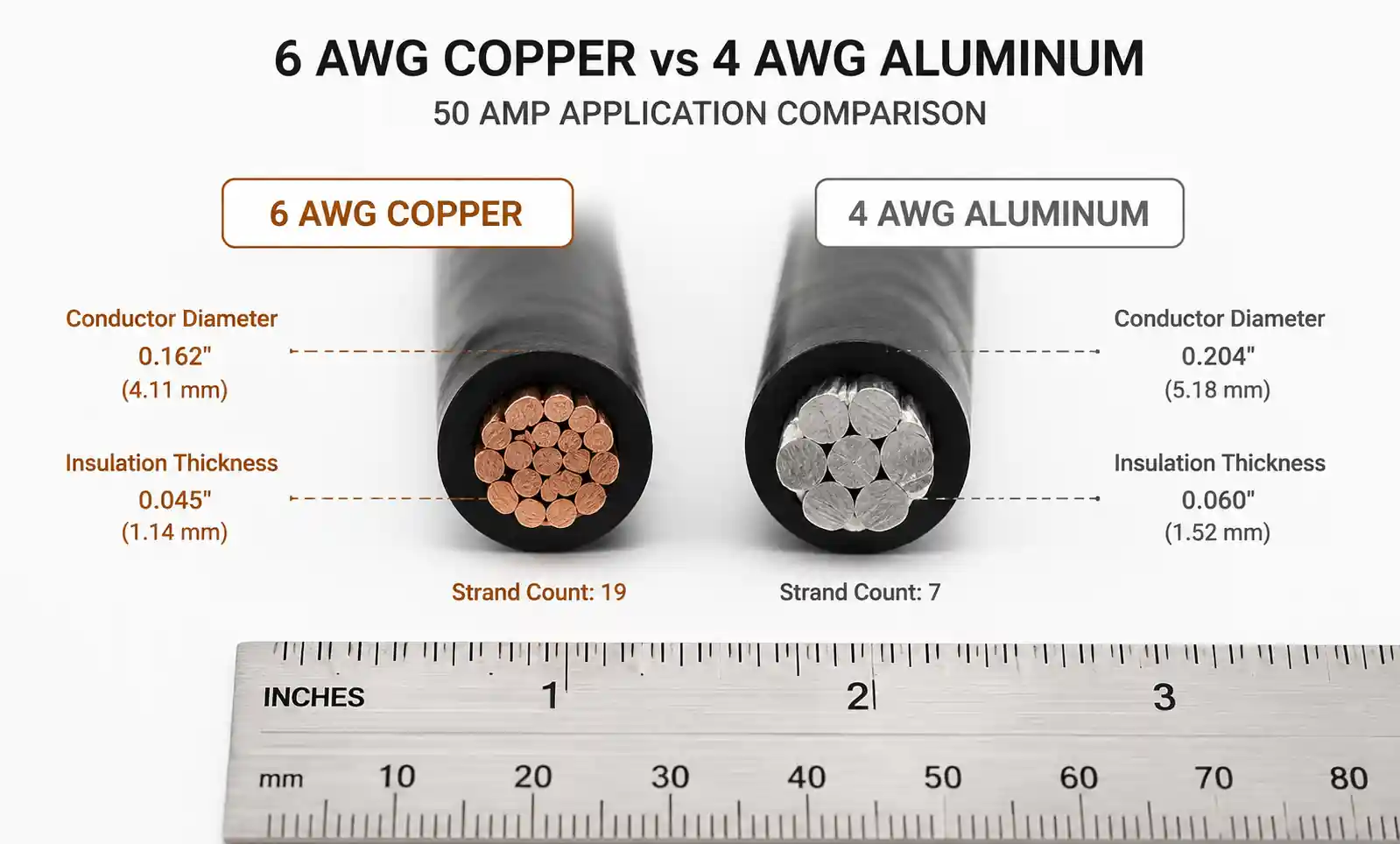
3. Conductor Material Comparison: Copper vs. Aluminum
Copper and aluminum are the two conductor materials approved for 50 amp circuits. Each material has distinct electrical and mechanical properties that influence selection decisions.
| Parameter | Copper | Aluminum | Impact on Selection |
|---|---|---|---|
| Resistivity (Ω·cm at 20°C) | 1.68 × 10⁻⁶ | 2.65 × 10⁻⁶ | Aluminum requires larger gauge for equivalent ampacity |
| Ampacity (6 AWG, 75°C THHN) | 65A | N/A | Copper 6 AWG meets 50A requirement |
| Ampacity (4 AWG, 75°C THHN) | 85A | 65A | Aluminum 4 AWG meets 50A requirement |
| Weight per foot (6 AWG) | 0.131 lb | N/A | Copper is significantly heavier |
| Weight per foot (4 AWG) | 0.207 lb | 0.098 lb | Aluminum reduces conduit fill and support requirements |
| Termination requirement | Standard lugs | Antioxidant compound + AL-rated lugs | Aluminum requires special termination procedures |
| Thermal expansion coefficient | Lower | Higher | Aluminum connections require periodic inspection |
| Cost per foot (relative) | Higher initial cost | Lower initial cost | Aluminum reduces material cost by 30-40% |
| Oxidation behavior | Forms conductive oxide | Forms insulating oxide | Aluminum requires proper termination to prevent high-resistance connections |
Copper is preferred for most residential and light commercial 50 amp circuits due to its superior conductivity, ease of termination, and long-term reliability. The standard choice is 6 AWG copper with THHN or THWN-2 insulation, which provides 65 amp ampacity at 75°C rating—adequate for a 50 amp breaker with the 80% continuous load factor.
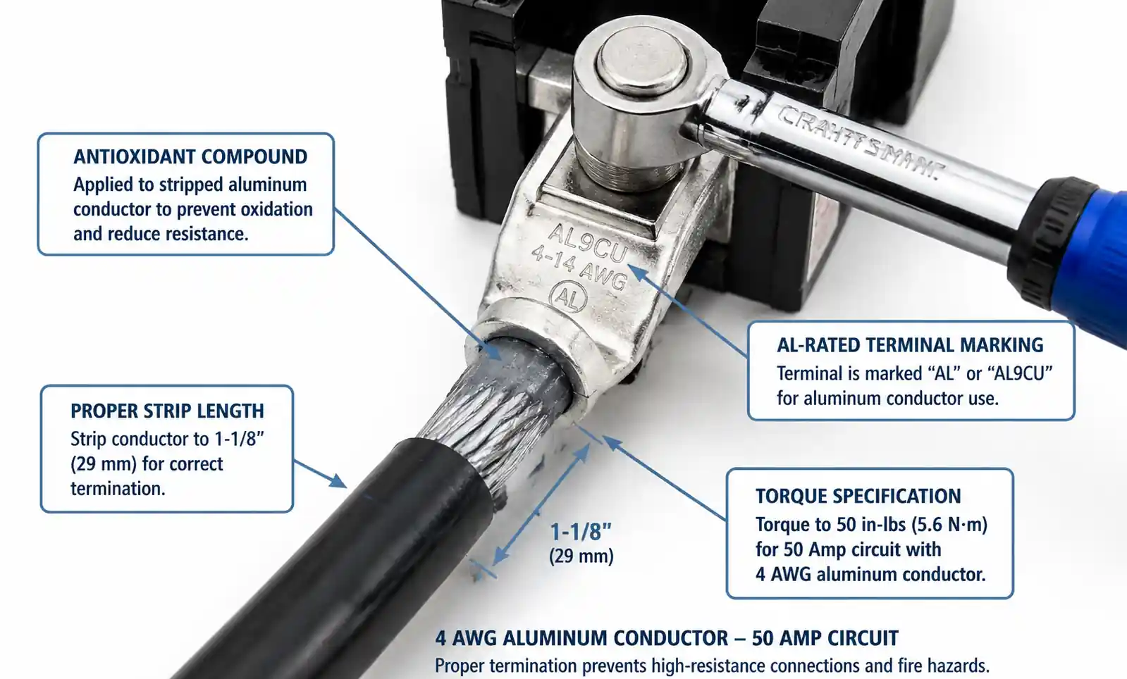
Aluminum wire is commonly specified for service entrance conductors, long feeder runs, and large commercial installations where material cost savings justify the larger gauge and special termination requirements. For 50 amp circuits, 4 AWG aluminum is the minimum size, providing 65 amp ampacity. All aluminum terminations must use antioxidant compound and connectors rated for aluminum (marked "AL" or "CO/ALR"). Failure to follow proper aluminum termination procedures is a leading cause of connection failures and fire hazards.
A common mistake is using aluminum wire with standard copper-rated devices. Always verify that circuit breakers, receptacles, and terminal blocks are rated for aluminum conductors before installation. Additionally, aluminum wire should never be used in conduit bends tighter than specified by NEC requirements, as the material is more prone to work hardening and strand breakage.
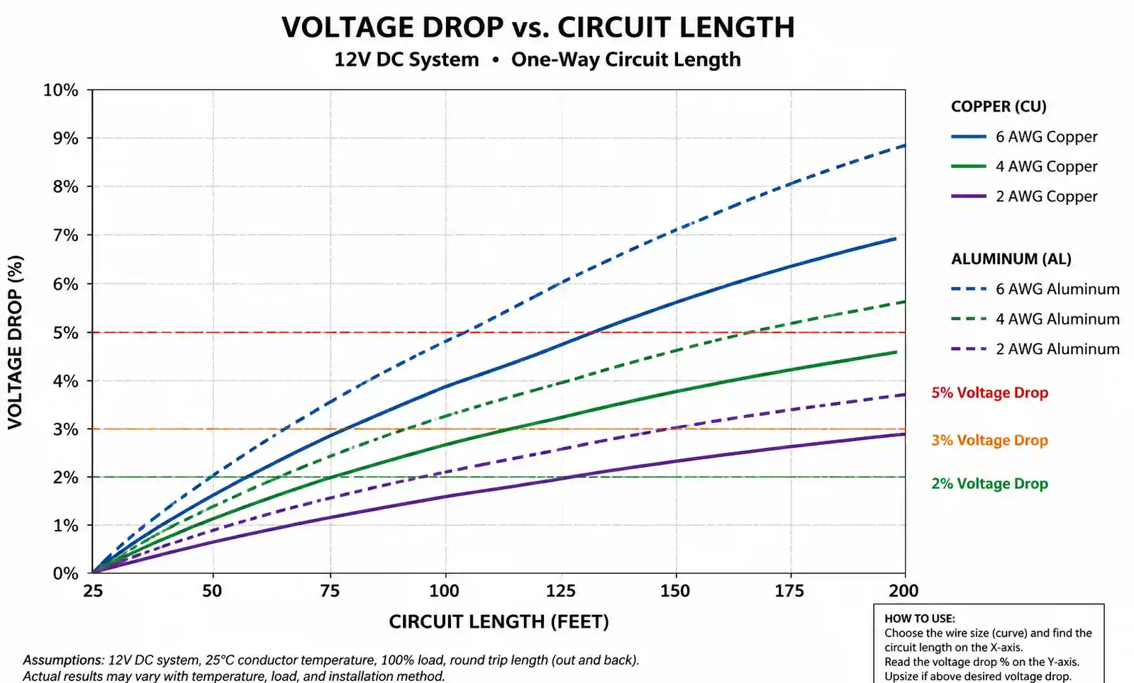
4. Voltage Drop Calculations and Acceptable Limits
Voltage drop is the reduction in voltage along a conductor due to wire resistance. Excessive voltage drop causes equipment to operate inefficiently, motors to overheat, and lighting to dim. The NEC recommends limiting voltage drop to 3% for feeder circuits and 5% total for combined feeder and branch circuits.
For a 50 amp circuit at 240V, a 3% voltage drop equals 7.2V, which is the maximum acceptable loss for proper equipment operation. The voltage drop formula for single-phase circuits is:
V_drop = (2 × K × I × L) / CM
Where:
- V_drop = voltage drop in volts
- K = resistance constant (12.9 for copper, 21.2 for aluminum)
- I = current in amperes
- L = one-way circuit length in feet
- CM = circular mil area of the conductor
The table below shows calculated voltage drop for 50 amp loads across different wire gauges and distances:
| Wire Size | Material | CM Area | 50 ft Run | 100 ft Run | 150 ft Run | Acceptable? |
|---|---|---|---|---|---|---|
| 8 AWG | Copper | 16,510 | 3.9V (1.6%) | 7.8V (3.2%) | 11.7V (4.9%) | No for >75 ft |
| 6 AWG | Copper | 26,240 | 2.5V (1.0%) | 4.9V (2.0%) | 7.4V (3.1%) | Yes up to 150 ft |
| 4 AWG | Copper | 41,740 | 1.5V (0.6%) | 3.1V (1.3%) | 4.6V (1.9%) | Yes, low drop |
| 6 AWG | Aluminum | 26,240 | 4.0V (1.7%) | 8.1V (3.4%) | 12.1V (5.0%) | No for >75 ft |
| 4 AWG | Aluminum | 41,740 | 2.5V (1.1%) | 5.1V (2.1%) | 7.6V (3.2%) | Marginal at 150 ft |
| 2 AWG | Aluminum | 66,360 | 1.6V (0.7%) | 3.2V (1.3%) | 4.8V (2.0%) | Yes, low drop |
Based on this analysis, 6 AWG copper is acceptable for runs up to 150 feet for most 50 amp applications. However, for critical loads such as medical equipment or precision machinery, voltage drop should be limited to 2% or less, which may require upsizing to 4 AWG copper for runs exceeding 75 feet.
For aluminum conductors, 4 AWG is the minimum practical size, but voltage drop at 150 feet approaches the acceptable limit. If the circuit length exceeds 125 feet, specify 2 AWG aluminum to maintain adequate voltage regulation. Always calculate voltage drop based on the actual continuous current, not the breaker rating, as many 50 amp circuits operate at reduced load levels.
5. Temperature Rating and Insulation Type Selection
Conductor ampacity is directly tied to insulation temperature rating. The three standard ratings are 60°C, 75°C, and 90°C, with higher ratings allowing greater current capacity. However, termination temperature limits often dictate the effective ampacity regardless of insulation rating.
Most circuit breakers and devices are rated for 75°C terminations, meaning that even if you install 90°C rated wire (such as THHN), you must use the 75°C ampacity column from NEC Table 310.16 when sizing the conductor. This is a frequent source of confusion in wire selection.
For 6 AWG copper:
- 60°C ampacity: 55A (insufficient for 50A breaker with continuous load)
- 75°C ampacity: 65A (acceptable for 50A breaker)
- 90°C ampacity: 75A (cannot be used unless terminations are rated 90°C)
For 4 AWG aluminum:
- 60°C ampacity: 60A (marginal)
- 75°C ampacity: 65A (acceptable for 50A breaker)
- 90°C ampacity: 75A (cannot be used unless terminations are rated 90°C)
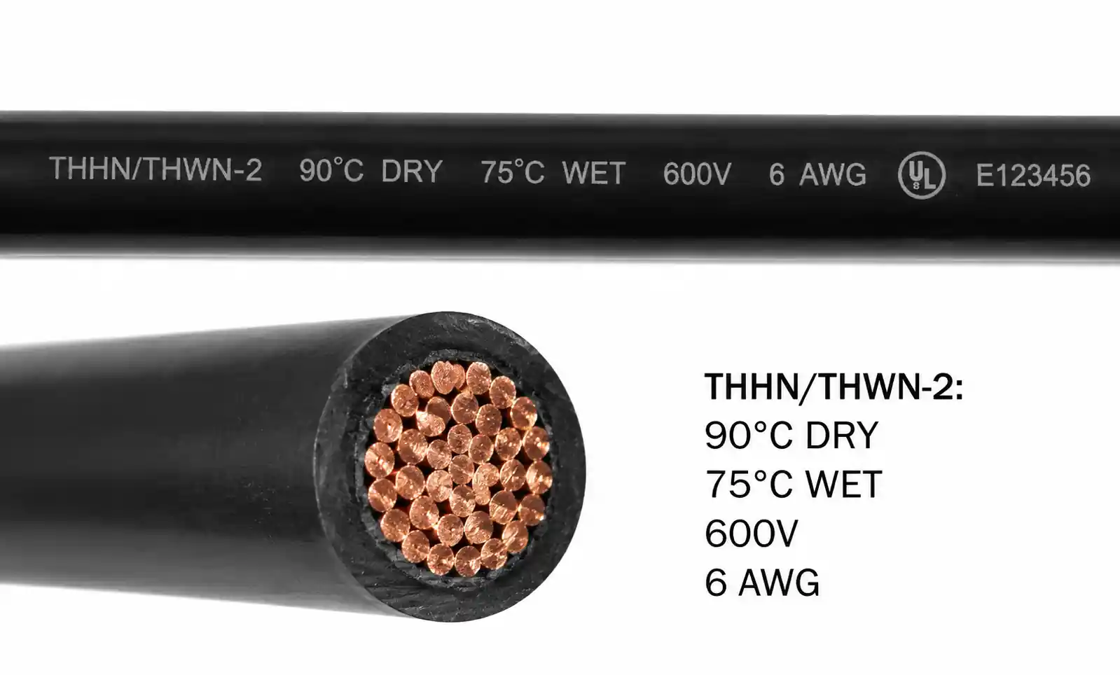
The most common insulation types for 50 amp circuits are THHN/THWN-2, which provide 90°C dry rating and 75°C wet rating. Despite the 90°C insulation rating, you must apply the 75°C ampacity for standard terminations. The benefit of 90°C insulation is improved derating performance in high ambient temperatures or when multiple conductors share a raceway.
When ambient temperature exceeds 30°C (86°F), or when more than three current-carrying conductors are installed in a conduit, apply NEC derating factors. For example, if six current-carrying conductors are in a conduit (two circuits), apply an 80% derating factor. A 6 AWG copper conductor with 75A base ampacity (90°C column) derated by 0.8 yields 60A effective ampacity—still adequate for a 50A circuit, but now using the 75°C termination rating of 65A would not provide enough margin.
6. Installation Considerations and Code Compliance
Proper installation is essential for long-term reliability and code compliance. The NEC Article 210 and 310 govern branch circuit and conductor installation requirements for 50 amp circuits.
Key installation requirements include:
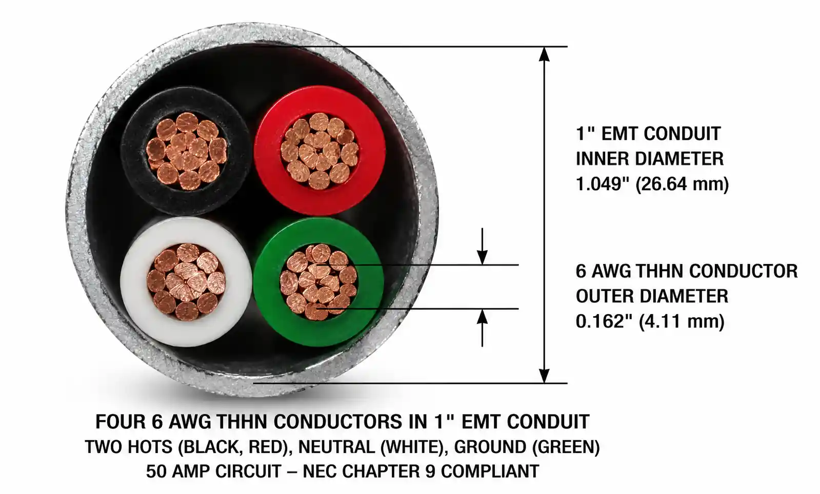
Conduit Fill: When installing conductors in conduit, you must comply with NEC Chapter 9 Table 4 conduit fill requirements. For three 6 AWG THHN conductors (hot, hot, neutral), the minimum conduit size is 1-inch EMT or 3/4-inch PVC Schedule 40. If you include a ground wire (four conductors total), 1-inch conduit is required for all raceway types.
Conductor Support: NEC requires conductor support at intervals not exceeding specific distances based on the raceway type. For example, rigid metal conduit must be supported within 3 feet of each box or enclosure and at intervals not exceeding 10 feet. Improper support can lead to conductor damage and connection stress.
Grounding: A 50 amp circuit requires an equipment grounding conductor sized per NEC Table 250.122. For a 50 amp circuit, the minimum ground wire size is 10 AWG copper or 8 AWG aluminum. Many installations use the same size ground as the phase conductors for simplicity, though this exceeds the minimum requirement.
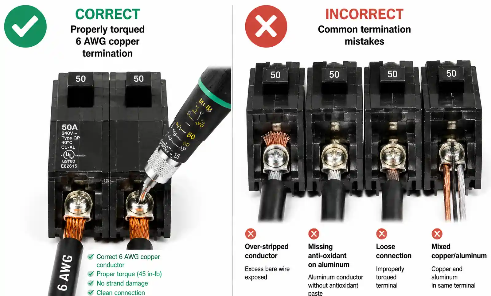
Termination Torque: All conductor terminations must be tightened to the manufacturer's specified torque values. For 6 AWG copper on typical 50 amp breakers, the torque specification is usually 35-45 lb-in. Under-torquing leads to high-resistance connections and overheating; over-torquing can damage the conductor or terminal. Always use a calibrated torque screwdriver or torque wrench for terminations.
Wet Locations: If the circuit is installed in a wet or damp location (outdoor installations, unfinished basements, etc.), use conductors with a "W" rating such as THWN-2. Standard THHN is not rated for wet locations and will fail prematurely if exposed to moisture.
Derating for Ambient Temperature: If the installation location has an ambient temperature above 30°C (86°F), you must apply temperature correction factors from NEC Table 310.15(B)(1). For locations with sustained temperatures of 40°C (104°F), such as attics or near heat sources, the correction factor for 75°C insulation is 0.88, reducing 6 AWG copper ampacity from 65A to 57A—no longer adequate for a 50A breaker. In such cases, upsize to 4 AWG copper.
7. Common Design Mistakes and How to Avoid Them
Based on field experience and code violation reports, the following design and installation errors are frequently observed in 50 amp circuit installations:
Mistake 1: Using 8 AWG copper for short runs Some installers assume that 8 AWG copper (rated 50A at 75°C) is sufficient for a 50 amp breaker. However, NEC requires conductors to be sized at 125% of continuous load, meaning a 50 amp breaker needs wire rated for at least 62.5A. The minimum acceptable size is 6 AWG copper (65A) or 4 AWG aluminum (65A). Using 8 AWG creates a code violation and safety hazard.
Mistake 2: Ignoring voltage drop on long runs Many designs specify 6 AWG copper for all 50 amp circuits without calculating voltage drop. For circuits exceeding 100 feet, voltage drop may exceed acceptable limits, causing equipment malfunction. Always calculate actual voltage drop for the specific installation and upsize conductors if needed. For EV chargers and other continuous loads, aim for 2% voltage drop or less.
Mistake 3: Using copper-rated terminations with aluminum wire Aluminum wire must only be terminated on devices and breakers specifically rated for aluminum (marked "AL" or "CO/ALR"). Standard copper-only terminations create high-resistance connections with aluminum, leading to overheating and fire risk. Additionally, aluminum terminations require antioxidant compound to prevent oxidation at the connection interface.
Mistake 4: Failing to apply derating factors When multiple circuits share a conduit, or when ambient temperature exceeds 30°C, conductors must be derated per NEC requirements. A common error is specifying 6 AWG copper based on the 75°C ampacity of 65A without considering that four circuits in a conduit require 80% derating, reducing ampacity to 52A—insufficient for a 50A breaker when considering the 125% continuous load rule.
Mistake 5: Mixing wire sizes within a circuit All ungrounded and grounded conductors (hot and neutral) in a 50 amp circuit must be the same size and material. Some installers mistakenly use a smaller neutral wire, assuming reduced current in the neutral conductor. This violates NEC requirements and creates a serious safety hazard. The equipment ground conductor can be smaller (per NEC Table 250.122), but all current-carrying conductors must be identically sized.
Mistake 6: Improper conductor bundling in attics or hot environments Installing multiple conductors in a bundle or conduit within a high-temperature environment (such as an attic) requires applying both temperature derating and conductor bundling derating factors. The combined effect can significantly reduce ampacity. For example, six current-carrying conductors in a 50°C attic would require derating to approximately 56% of base ampacity (0.88 temperature × 0.8 bundling × 0.8 for more than 3 conductors), making 6 AWG copper inadequate.
8. FAQ
What is the minimum wire size for a 50 amp breaker?
The minimum wire size for a 50 amp breaker is 6 AWG copper or 4 AWG aluminum, assuming 75°C rated insulation (THHN/THWN-2) and standard installation conditions. This provides 65 amp ampacity, meeting the NEC requirement to size conductors at 125% of continuous load (50A × 1.25 = 62.5A required ampacity).
Can I use 8 AWG copper for a 50 amp circuit?
No. Although 8 AWG copper has a 50 amp rating at 75°C, NEC Article 210.19(A)(1) requires branch circuit conductors to have ampacity not less than 125% of the continuous load. For a 50 amp breaker, this means the conductor must be rated for at least 62.5 amps, which requires 6 AWG copper (65A) or larger.
How do I calculate voltage drop for a 50 amp circuit?
Use the formula: V_drop = (2 × K × I × L) / CM, where K is 12.9 for copper or 21.2 for aluminum, I is current in amps, L is one-way length in feet, and CM is the circular mil area of the conductor. For a 100-foot run with 6 AWG copper (26,240 CM) at 50 amps: V_drop = (2 × 12.9 × 50 × 100) / 26,240 = 4.9V, or 2.0% at 240V.
When should I use 4 AWG instead of 6 AWG copper?
Upsize to 4 AWG copper when: (1) circuit length exceeds 100 feet and you need to limit voltage drop below 2%, (2) ambient temperature exceeds 40°C and derating reduces 6 AWG ampacity below 62.5A, (3) more than three current-carrying conductors share a raceway requiring significant derating, or (4) the application involves continuous loads where voltage regulation is critical, such as medical equipment or precision machinery.
Is aluminum wire acceptable for 50 amp circuits?
Yes, aluminum wire is code-compliant and commonly used for 50 amp circuits, particularly for longer runs or service entrance applications where cost savings are significant. Use 4 AWG aluminum minimum, which provides 65A ampacity at 75°C. All terminations must use antioxidant compound and be rated for aluminum (marked "AL" or "CO/ALR"). Periodic inspection of aluminum connections is recommended to detect any signs of oxidation or loosening.
What size ground wire is required for a 50 amp circuit?
NEC Table 250.122 requires a minimum 10 AWG copper or 8 AWG aluminum equipment grounding conductor for a 50 amp circuit. Many installations use the same size ground as the phase conductors (6 AWG copper or 4 AWG aluminum) for installation convenience and additional safety margin, though this exceeds the minimum code requirement.
How does conduit fill affect 50 amp wire sizing?
Conduit fill does not change the minimum wire size, but it does affect ampacity when more than three current-carrying conductors are installed in a raceway. NEC Table 310.15(B)(3)(a) requires applying derating factors: 80% for 4-6 conductors, 70% for 7-9 conductors. If six current-carrying conductors (three circuits) share a conduit, 6 AWG copper with 90°C insulation has an adjusted ampacity of 60A (75A × 0.8), which still meets the 62.5A requirement when using the 75°C termination rating of 65A.
Can I run a 50 amp circuit in PVC conduit?
Yes, PVC conduit is acceptable for 50 amp circuits if properly sized. For three 6 AWG THHN conductors, the minimum PVC Schedule 40 conduit size is 3/4 inch. If you include a separate ground wire (four conductors total), increase to 1-inch PVC. Ensure the PVC is rated for the installation environment—Schedule 40 for general use, Schedule 80 for areas requiring additional mechanical protection. For outdoor or underground installations, use conductors rated for wet locations (THWN-2).
Conclusion
Selecting the best wire size for 50 amp circuits requires careful consideration of conductor material, circuit length, voltage drop, ambient temperature, and installation method. For most residential and commercial applications, 6 AWG copper with THHN/THWN-2 insulation provides the optimal balance of ampacity, cost, and installation ease for circuits up to 100 feet.
For longer runs, continuous loads, or elevated ambient temperatures, upsize to 4 AWG copper or specify 2 AWG aluminum to maintain acceptable voltage drop and ensure long-term reliability. Always apply NEC derating factors when multiple conductors share a raceway or when ambient temperature exceeds 30°C.
Before finalizing your wire selection, verify that your design meets NEC requirements, calculate actual voltage drop for the specific installation distance, and confirm that all terminations and devices are rated for the conductor material and temperature class. When in doubt, consult the latest edition of the NEC or work with a licensed electrical engineer to validate your design.
For additional technical support, refer to the NEC Handbook, manufacturer application notes for specific equipment, and conductor ampacity tables. If you need assistance selecting wire for a complex installation or have questions about specific code requirements, contact a qualified electrical contractor or consulting engineer for project-specific guidance.