HRC Fuse Selection Guide: Technical Parameters, Applications, and Design Considerations
High Rupturing Capacity (HRC) fuses are critical protection devices in industrial, commercial, and power distribution systems where high fault currents demand reliable interruption. This guide helps electrical engineers, facility managers, and procurement teams select the right HRC fuse for their applications by examining key technical parameters, performance trade-offs, and common design pitfalls.
Table of Contents
- What is an HRC Fuse and Why It Matters
- Key Technical Parameters Explained
- How to Choose the Right HRC Fuse for Your Application
- Performance Comparison: HRC Fuse vs. MCB vs. MCCB
- Design Considerations and Common Pitfalls
- Supply Chain and Sourcing Considerations
- FAQ
- Conclusion and Recommended Next Steps
1. What is an HRC Fuse and Why It Matters
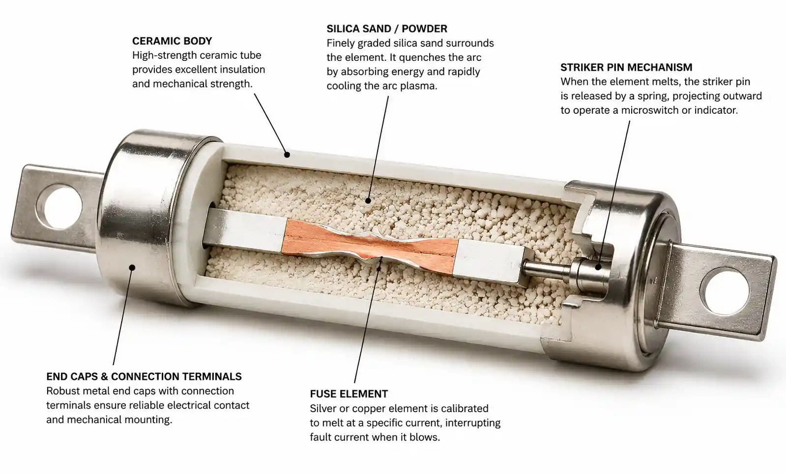
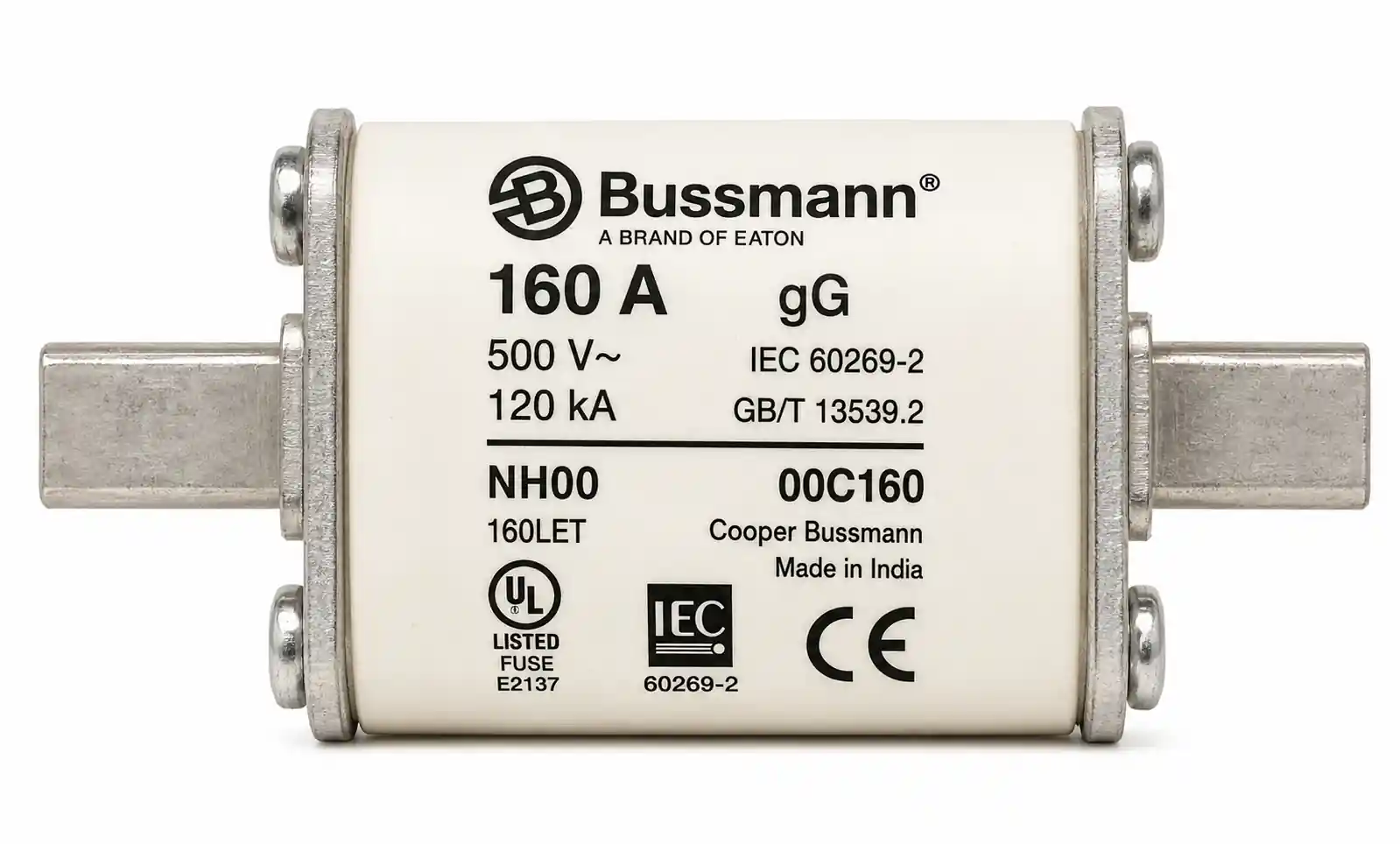
An HRC fuse is a current-limiting protective device designed to safely interrupt high-magnitude fault currents—often exceeding 80 kA—within milliseconds. Unlike standard fuses, HRC fuses use a silver or copper element surrounded by silica sand or ceramic powder filler material, which absorbs arc energy and prevents explosive rupture during overcurrent events.
The term "high rupturing capacity" refers to the fuse's ability to break extremely high short-circuit currents without causing damage to surrounding equipment or creating safety hazards. This capability is essential in industrial motor control centers, power distribution systems, transformer protection circuits, and renewable energy installations where fault currents can reach tens of thousands of amperes.
HRC fuses provide several advantages over other protection devices: faster response time than circuit breakers under high fault conditions, no maintenance requirements, consistent trip characteristics that don't degrade over time, and lower initial cost for high-current applications. However, they are single-use devices that require replacement after operation, making proper selection critical to minimize downtime and maintenance costs.
The selection of HRC fuses directly impacts system reliability, safety compliance, equipment protection, and total cost of ownership. Undersized fuses lead to nuisance tripping and production losses, while oversized fuses fail to provide adequate protection and may violate electrical codes.
2. Key Technical Parameters Explained
Understanding HRC fuse datasheets requires familiarity with several critical parameters that determine protection performance and compatibility.
Breaking Capacity (Rupturing Capacity)
Breaking capacity, measured in kA (kiloamperes), represents the maximum fault current the fuse can safely interrupt. HRC fuses typically offer breaking capacities from 50 kA to 200 kA. This parameter must exceed the maximum prospective short-circuit current at the installation point, which is calculated based on transformer rating, impedance, and upstream protection.
In industrial facilities with large transformers or multiple parallel sources, prospective fault currents can easily exceed 100 kA. Selecting an HRC fuse with inadequate breaking capacity can result in violent failure, equipment damage, and safety hazards. Always include a safety margin of at least 20% above the calculated fault current.
Rated Current (In)
The rated current is the continuous current the fuse can carry indefinitely without deterioration. HRC fuses are available in ratings from 2A to 1250A for different voltage classes. The rated current must be selected based on the normal load current, ambient temperature, and any derating factors.
A common mistake is selecting rated current too close to the normal operating current. HRC fuses should typically be rated at 125-150% of the maximum continuous load current to account for harmonic content, starting currents, and ambient temperature variations. In motor protection applications, fuses rated at 150-200% of motor full-load current are typical to accommodate inrush currents.
Voltage Rating
HRC fuses are categorized by voltage class: low voltage (up to 1000V AC), medium voltage (1kV to 36kV), and high voltage (above 36kV). The voltage rating must meet or exceed the system voltage. Using a fuse with insufficient voltage rating can lead to arc extinction failure and continued fault current flow.
International standards define voltage ratings differently—IEC 60269 uses utilization categories (gG, gM, aM) while UL/CSA standards specify AC/DC voltage ratings. Always verify that the fuse voltage rating matches both the system voltage and the applicable standard for your region.
Time-Current Characteristics (I²t)
The I²t value, measured in A²s, represents the thermal energy the fuse allows to pass before clearing. This parameter is critical for coordination with upstream and downstream protection devices and for protecting sensitive equipment like semiconductors.
Low I²t fuses provide faster clearing and better component protection but may be prone to nuisance tripping from transient overloads. High I²t fuses tolerate transient currents better but provide less protection for semiconductor devices. In variable frequency drive (VFD) applications, semiconductor-grade HRC fuses with very low I²t values are essential to prevent expensive inverter damage.
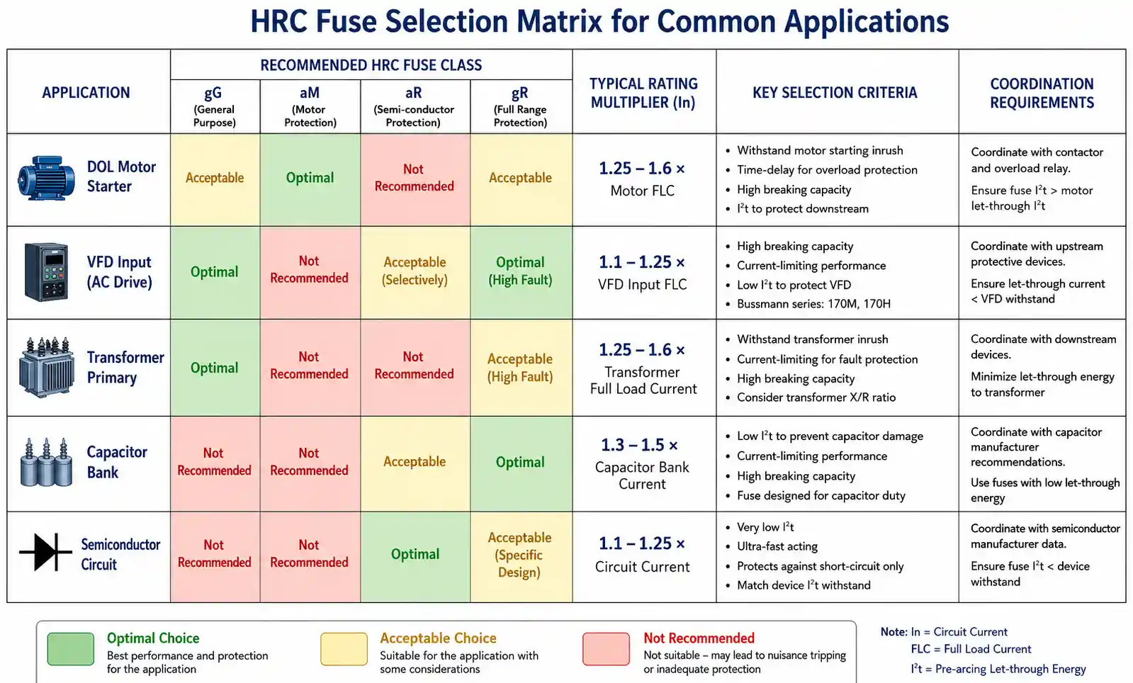
Fuse Class and Operating Characteristics
HRC fuses are classified by their time-current characteristics:
- gG (General Purpose): Full-range breaking, suitable for cable and general equipment protection
- gM (Motor Protection): Designed to withstand motor starting currents while providing short-circuit protection
- aM (Motor Backup): Provides short-circuit protection only, must be used with overload relay
- Semiconductor (Ultra-Fast): Extremely fast-acting for protecting thyristors, IGBTs, and diodes
Selecting the wrong class is a frequent error in motor control applications. Using gG fuses for direct-on-line motor starters often results in nuisance tripping during startup, while using aM fuses without proper overload protection violates electrical codes.
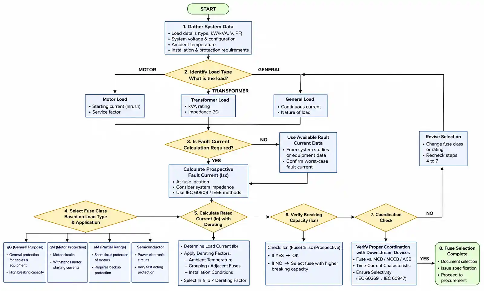
3. How to Choose the Right HRC Fuse for Your Application
HRC fuse selection follows a systematic methodology that considers load characteristics, fault current levels, coordination requirements, and environmental conditions.
Step 1: Calculate Maximum Prospective Fault Current
Determine the available short-circuit current at the point of installation using the formula:
Isc = (V × 1000) / (√3 × Z)
Where V is the system voltage, and Z is the total impedance from source to fault point. For transformer-fed systems, use transformer impedance percentage and rating:
Isc = (Transformer kVA × 100) / (√3 × V × Z%)
Always verify calculations with utility data or conduct short-circuit studies for complex installations. The selected HRC fuse breaking capacity must exceed this value with appropriate safety margin.
Step 2: Determine Load Current and Type
Identify the normal operating current and load characteristics. For resistive loads, select rated current at 125-135% of maximum load current. For inductive loads like motors, account for starting current using:
- DOL (Direct-On-Line) motors: 150-200% of full-load current
- Star-delta starters: 125-150% of full-load current
- VFD-controlled motors: 110-125% of full-load current
For capacitive loads like power factor correction capacitors, account for inrush currents that can reach 100-200 times steady-state current. Time-delay or gG-class fuses are typically required.
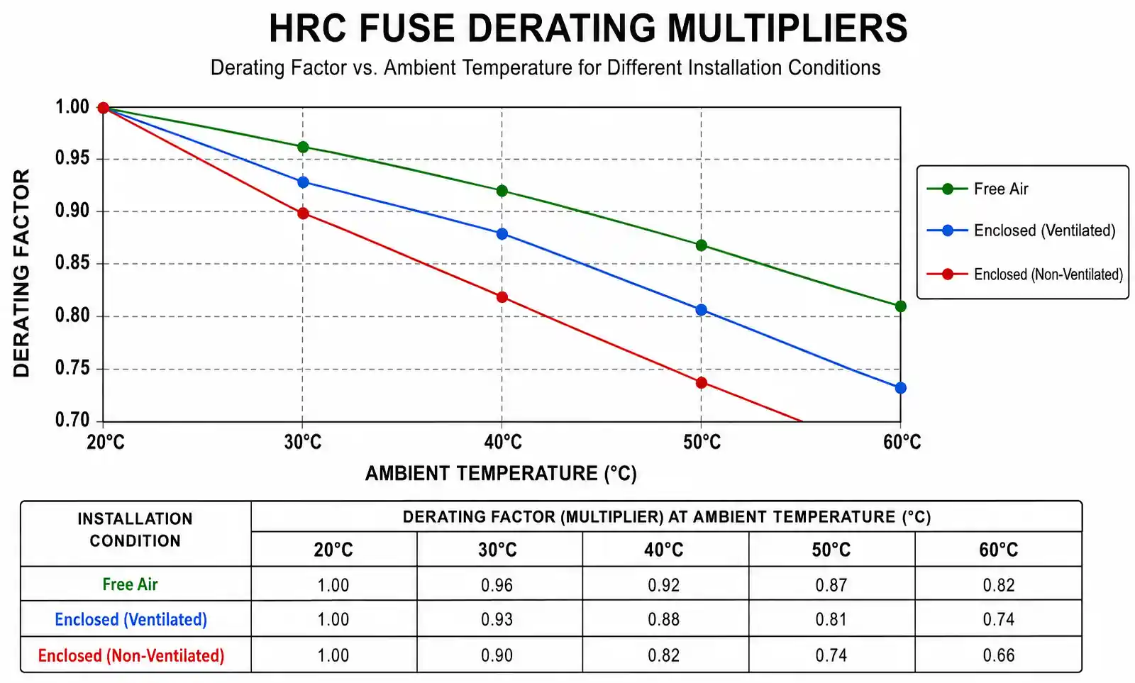
Step 3: Apply Derating Factors
HRC fuse ratings are based on specific test conditions (typically 20°C ambient in free air). Apply correction factors for:
- Ambient temperature above 25°C: typically 0.9-0.95 derating per 10°C
- Enclosed installations: 0.8-0.9 factor depending on enclosure ventilation
- High altitude (above 1000m): 0.95-0.98 per 1000m elevation
- Harmonic content: 1.1-1.25 factor for nonlinear loads
Step 4: Verify Coordination
Check time-current coordination with upstream and downstream devices. The fuse must clear faster than upstream protection to provide selective coordination, but slower than downstream devices to avoid nuisance tripping.
For motor protection, HRC fuses must coordinate with overload relays—the relay should trip for sustained overloads while the fuse provides short-circuit protection only. For semiconductor protection, verify that fuse I²t is less than device withstand I²t at all current levels.
Step 5: Confirm Standards Compliance
Verify the selected fuse meets applicable standards:
- IEC 60269 (International)
- UL 248 (North America)
- BS 88 (UK/Commonwealth)
- GB/T 13539 (China)
Different standards have incompatible dimensions, ratings, and test requirements. A fuse certified to one standard may not be code-compliant or physically interchangeable in systems designed for another standard.
4. Performance Comparison: HRC Fuse vs. MCB vs. MCCB
Selecting between HRC fuses, Miniature Circuit Breakers (MCBs), and Molded Case Circuit Breakers (MCCBs) requires understanding their relative strengths in different application scenarios.
| Parameter | HRC Fuse | MCB | MCCB |
|---|---|---|---|
| Breaking capacity | 50-200 kA | 6-25 kA | 25-200 kA |
| Current rating range | 2-1250 A | 0.5-125 A | 15-2500 A |
| Response time @ 10× In | 0.01-0.1 s | 0.02-0.2 s | 0.02-0.15 s |
| Let-through energy (I²t) | Very low | Moderate | Moderate to high |
| Maintenance requirement | None (replace after operation) | Periodic testing recommended | Annual testing required |
| Service life | Single operation | 10,000-20,000 operations | 5,000-10,000 operations |
| Initial cost (100A, 50kA) | $15-40 | $25-60 | $150-400 |
| Replacement cost per trip | $15-40 | $0 | $0 |
| Selective coordination | Excellent (with proper sizing) | Good | Excellent (with electronic trip) |
| Arc flash incident energy | Low | Moderate | Moderate to high |
This comparison reveals that HRC fuses excel in high-fault-current applications where fast clearing and low let-through energy are critical. In semiconductor protection, motor starter panels, and transformer primary protection, HRC fuses provide superior performance at lower cost than equivalent-rated MCCBs.
However, circuit breakers offer advantages for frequent overload conditions, remote monitoring requirements, or applications where manual reset is preferred over fuse replacement. In commercial lighting panels, HVAC systems, and building distribution boards, MCBs and MCCBs typically provide better total cost of ownership.
Application-Specific Recommendations
| Application | Recommended Device | Key Considerations |
|---|---|---|
| Motor starter (DOL) | HRC fuse + overload relay | High inrush tolerance, low cost, excellent short-circuit protection |
| VFD input protection | HRC semiconductor fuse | Fast clearing protects expensive inverter components |
| Transformer primary | HRC fuse (gG class) | High breaking capacity, low maintenance, cost-effective |
| Building distribution | MCCB or MCB | Resettable, better for frequent overloads, easier troubleshooting |
| PV combiner box | HRC fuse (gPV class) | DC rating, reverse current protection, outdoor rated |
| Capacitor bank | HRC fuse (gG or aR class) | Handles high inrush, prevents capacitor rupture |
The choice often comes down to total cost analysis over the equipment lifetime. For equipment with low trip frequency (transformers, main distribution), HRC fuses provide lowest total cost. For equipment with frequent trips or requiring remote monitoring, circuit breakers justify their higher initial cost.
5. Design Considerations and Common Pitfalls
Proper HRC fuse application requires attention to several design details that are often overlooked in initial installations.
Coordination with Downstream Protection
A frequent error in motor control circuits is failing to coordinate HRC fuses with motor overload relays. The fuse must provide short-circuit protection only, while the overload relay handles sustained overload conditions. If the fuse I²t is too low, it may clear during motor starting before the overload relay can respond, causing nuisance tripping.
Use manufacturer coordination tables or perform time-current curve analysis to verify proper selectivity. The fuse minimum melting time at any current level should be at least 1.5-2 times longer than the overload relay clearing time at the same current.
Voltage Drop and Conductor Sizing
HRC fuses introduce resistance into the circuit, typically 0.1-0.5 milliohms depending on rating and construction. In high-current applications, this resistance can cause measurable voltage drop and power dissipation. For a 400A HRC fuse with 0.3 mΩ resistance, power dissipation reaches approximately 48W under full load.
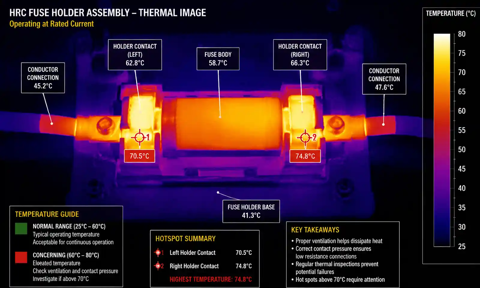
Ensure adequate ventilation around fuse holders and account for fuse voltage drop in conductor sizing calculations. In sensitive equipment applications, measure voltage at load terminals under full current to verify compliance with equipment tolerance specifications.
Ambient Temperature Effects
HRC fuse performance degrades significantly at elevated ambient temperatures. A fuse rated for 400A at 25°C may need to be derated to 360A at 50°C ambient—a 10% reduction. In enclosed switchgear or outdoor installations in hot climates, failure to account for temperature can lead to premature fuse operation.
Some manufacturers provide temperature correction curves in their technical documentation. If operating above 40°C ambient or in enclosed spaces with limited airflow, consult manufacturer application notes for proper derating factors.
Mechanical Stress and Vibration
In industrial environments with heavy machinery or seismic activity, mechanical vibration can fatigue fuse elements or loosen connections. This is particularly critical for blade-type fuse holders, which rely on spring pressure for electrical contact.
Specify vibration-resistant fuse holders for motor control centers, crane systems, and outdoor substations. Periodic inspection of fuse holder contacts and retorquing of bolted connections should be part of preventive maintenance programs, typically annually or after any significant vibration event.
Series vs. Parallel Fuse Application
Never parallel HRC fuses to achieve higher current ratings. Manufacturing tolerances mean one fuse will always carry slightly more current and will clear first, immediately overloading the remaining fuses and causing cascade failure. If required current rating exceeds available fuse ratings, use multiple circuits or upgrade to higher-rated fuses and conductors.
Series fuses (backup fuses) can be used in specific applications like transformer protection, where a high-voltage fuse provides primary protection and a low-voltage fuse provides backup. However, coordination analysis is essential to ensure the intended fuse operates under all fault scenarios.
Arc Flash Hazard Reduction
One often-overlooked advantage of HRC fuses is their contribution to arc flash hazard reduction. The current-limiting action of HRC fuses significantly reduces incident energy compared to non-current-limiting devices. In some installations, specifying HRC fuses instead of MCCBs can reduce arc flash PPE category from 3 to 1, improving worker safety and reducing compliance costs.
Calculate arc flash incident energy with fuses in place using IEEE 1584 or NFPA 70E methods. Document the reduced hazard level on equipment labels and in safety procedures.
6. Supply Chain and Sourcing Considerations
HRC fuse procurement requires attention to availability, standardization, and lifecycle management to minimize downtime and inventory costs.
Standardization and Interchangeability
A common procurement mistake is mixing fuse standards within a facility. IEC and UL fuses are not mechanically or electrically interchangeable, despite similar ratings. An IEC 60269 fuse will not fit a UL 248 fuse holder, and attempting to force-fit can create safety hazards.
Standardize on one fuse system (IEC or UL) throughout your facility. Document the standard in specifications and maintenance procedures. Train maintenance personnel to identify correct replacement fuses using dimensional drawings and catalog numbers, not just current ratings.
Lead Time and Inventory Planning
Common HRC fuse ratings (63A, 100A, 200A, 400A) from major manufacturers typically have 1-4 week lead times from authorized distributors. Specialized ratings, high-voltage fuses, or less common standards may require 6-12 weeks, especially for European or Asian manufacturers.
Maintain critical spares inventory for:
- Fuses protecting production-critical equipment
- Specialty fuses with long lead times (>4 weeks)
- Fuses in high-trip-frequency applications
For a typical industrial facility, stocking 2-3 spare fuses per rating for critical circuits provides good balance between inventory cost and downtime risk. Use inventory management systems to track fuse usage patterns and adjust stock levels accordingly.
Obsolescence and Long-Term Availability
Fuse manufacturers occasionally discontinue product lines or change catalog numbering systems. For equipment with 20-30 year service life, fuse availability can become a long-term maintenance concern. When specifying equipment, verify:
- Manufacturer commitment to long-term product availability
- Availability of cross-reference data for alternative suppliers
- Physical interchangeability with competing products
Major manufacturers like Mersen, Eaton/Bussmann, Littelfuse, and Ferraz Shawmut maintain stable product lines and provide obsolescence notifications with recommended replacements. Building specifications should include a clause requiring use of manufacturers with established long-term product support.
Counterfeit Detection
Counterfeit fuses are a significant problem in some markets, particularly for popular ratings and brands. Counterfeit fuses may lack proper arc-quenching fill material, use substandard element materials, or have incorrect breaking capacity ratings—all creating serious safety hazards.
Purchase HRC fuses only from authorized distributors with verifiable supply chain documentation. Be suspicious of unusually low prices or suppliers unable to provide manufacturer authorization. Inspect fuses for:
- Proper marking and certification marks (UL, CSA, IEC, CE)
- Correct manufacturer logo and typography
- Quality of printing and label adhesion
- Consistency of physical dimensions and weight
For critical applications, consider requesting manufacturer certification or test reports, particularly for large procurement quantities.
7. FAQ
What is the difference between HRC fuse and rewirable fuse?
HRC fuses use a precisely-engineered silver or copper element surrounded by arc-quenching material, providing consistent performance, high breaking capacity (50-200 kA), and current-limiting action. Rewirable fuses use a simple wire element in air, offering only 1-3 kA breaking capacity with unpredictable performance. HRC fuses are mandatory in modern industrial and commercial installations where fault currents exceed rewirable fuse capabilities.
Can I use an HRC fuse with higher current rating if exact rating is unavailable?
No. Oversizing defeats the protection purpose and may violate electrical codes. The fuse must be selected based on conductor ampacity and protected equipment ratings. If the correct rating is unavailable, source from an alternative supplier or temporarily reduce load until proper fuses arrive. Never compromise on protection ratings.
How do I calculate required breaking capacity for my installation?
Calculate prospective short-circuit current using transformer rating and impedance, or obtain from utility fault current data. For transformer-fed systems: Isc (kA) = (Transformer kVA × 100) / (√3 × Voltage × Z%). Select fuse breaking capacity at least 25% higher than calculated fault current. For complex systems, perform short-circuit study using software like ETAP or SKM PowerTools.
What causes nuisance fuse blowing in motor circuits?
Common causes include: undersized fuse rating (should be 150-200% of motor FLA for DOL starting), incorrect fuse class (use gM or aM for motor applications, not gG), excessive ambient temperature without derating, mechanical problems causing locked rotor or excessive starting time, or voltage sags during starting. Review motor starting current and duration, verify fuse selection matches manufacturer motor fuse tables.
Are HRC fuses suitable for DC applications?
Standard AC-rated HRC fuses cannot be used for DC circuits above 50V. DC interruption is more difficult than AC because there is no natural current zero crossing to extinguish the arc. DC-rated fuses use different element design and additional arc-quenching material. Always specify fuses with explicit DC voltage and current ratings for solar PV, battery systems, EV charging, or DC industrial equipment. Using AC fuses in DC circuits creates serious fire and explosion hazards.
How often should HRC fuses be replaced preventively?
HRC fuses do not have a defined service life and do not require preventive replacement unless they have operated (cleared a fault). However, periodic inspection should verify: no visible damage or discoloration, proper contact pressure in fuse holders, no signs of overheating (discolored terminals), secure mounting. In high-vibration or high-temperature environments, annual inspection is recommended. Replace any fuse showing physical damage or signs of overheating regardless of whether it has tripped.
What documentation should I maintain for HRC fuse installations?
Maintain: fuse schedule showing location, rating, class, and catalog number for each fuse; manufacturer datasheets with time-current curves; coordination study results; spare parts inventory list; replacement history log; arc flash analysis showing fuse contribution to incident energy reduction. This documentation supports troubleshooting, ensures correct replacement parts, and demonstrates code compliance during inspections.
Can HRC fuses protect against ground faults?
Standard HRC fuses provide phase-to-phase and phase-to-neutral fault protection but offer limited ground fault protection. Ground fault currents may be too low to operate fuses quickly, allowing dangerous conditions to persist. For comprehensive protection, combine HRC fuses with ground fault relays or residual current devices (RCDs) in accordance with electrical codes. In IT or high-resistance grounded systems, specialized ground fault detection equipment is required.
8. Conclusion and Recommended Next Steps
HRC fuse selection is a critical design decision that impacts system safety, reliability, and total cost of ownership. The key selection parameters—breaking capacity, rated current, voltage class, I²t value, and fuse class—must be matched to your specific application considering load characteristics, fault current levels, coordination requirements, and environmental conditions.
For motor protection applications, specify gM or aM class fuses rated at 150-200% of motor full-load current, and verify coordination with overload relays. For semiconductor protection in VFDs or power converters, use ultra-fast semiconductor-grade fuses with I²t ratings below device withstand ratings. For general power distribution and transformer protection, gG-class fuses provide reliable, cost-effective protection.
Before finalizing your selection, complete these verification steps: calculate maximum prospective fault current at installation point and confirm fuse breaking capacity exceeds this value with adequate margin; apply temperature and enclosure derating factors to rated current; verify time-current coordination with upstream and downstream protective devices; confirm compliance with applicable electrical codes and standards for your region; source from authorized distributors with verifiable supply chain documentation.
If you need assistance with short-circuit calculations, coordination studies, or arc flash analysis for your specific installation, consult with electrical engineers experienced in industrial power systems. Most major fuse manufacturers provide application engineering support and selection software tools to help specify appropriate fuses for complex applications.
For detailed technical specifications, download manufacturer datasheets and application notes for your selected fuse ratings. When installing new equipment or retrofitting existing systems, work with authorized distributors who can provide technical support, cross-reference data, and long-term product availability commitments.