




Buck Converter Design Guide: Selection, Performance, and Application
When designing power management for embedded systems, automotive electronics, or industrial equipment, the buck converter is one of the most widely deployed DC-DC topologies. It efficiently steps down higher input voltages to lower outputs for powering microcontrollers, sensors, and communication modules. Selecting the right one requires understanding key parameters, efficiency-cost trade-offs, and design pitfalls that can kill reliability.
Table of Contents
- What Is a Buck Converter and How Does It Work?
- Key Parameters for Buck Converter Selection
- Buck Converter vs. Linear Regulator: When to Use Each
- Design Considerations for High-Efficiency Apps
- Common Design Mistakes and How to Avoid Them
- FAQ
- Conclusion
What Is a Buck Converter and How Does It Work?
A buck converter steps down voltage with 85-95% efficiency. Unlike linear regulators that burn excess voltage as heat, buck converters use a switching element (MOSFET), inductor, diode (or sync rectifier), and output caps to transfer energy efficiently.
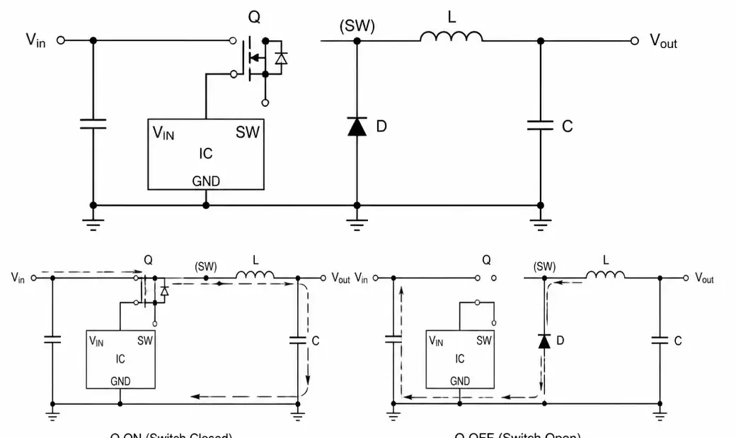
Buck converter basic circuit topology with MOSFET switch inductor and output capacitor
The switch turns on and off at a fixed frequency (300 kHz to 2 MHz). When on, current flows through the inductor to the load, storing energy. When off, the inductor's collapsing field maintains current through the freewheeling diode. Duty cycle sets output voltage: Vout = Vin × D.
Synchronous buck converters replace the diode with a second MOSFET, reducing conduction losses and improving efficiency – preferred for battery-powered apps where every efficiency point extends runtime.
Key Parameters for Buck Converter Selection
Focus on parameters that impact performance, thermal management, and cost.
| Parameter | Typical Range | Design Impact | Priority |
|---|---|---|---|
| Input voltage range | 4.5V – 60V | Must handle worst-case transients | High – verify supply tolerance |
| Output voltage | 0.8V – 36V | Match load requirements | High – compatibility with load |
| Output current | 0.5A – 30A+ | Determines power stage sizing | High – peak and continuous loads |
| Switching frequency | 300 kHz – 2 MHz | Higher freq = smaller passives, more loss | Medium – size vs. efficiency |
| Efficiency | 85% – 96% | Impacts thermal and battery life | High – check at your operating point |
| Quiescent current | 10 µA – 5 mA | Critical for battery sleep modes | High for battery, medium for mains |
| Load regulation | ±1% – ±5% | Output stability under load variation | Medium – tighten for analog |
| Line regulation | ±0.5% – ±2% | Stability with input variation | Medium – critical for automotive |
For automotive with 12V battery (9V-16V range), pick a device rated for at least 18V. For IoT sensor nodes from coin cells, quiescent current dominates over peak efficiency.
Switching frequency matters: higher (1-2 MHz) shrinks inductors and caps but increases switching loss and EMI. Lower (300-500 kHz) improves efficiency but needs larger passives. For noise-sensitive apps like audio or precision analog, pick frequencies outside the signal band or use spread-spectrum.
Buck Converter vs. Linear Regulator: When to Use Each
The choice depends on voltage differential, load current, efficiency needs, and noise sensitivity.
| Factor | Buck Converter | Linear Regulator | Best Use |
|---|---|---|---|
| Efficiency | 85% – 96% | (Vout/Vin) × 100% | Buck: high current or large Vin-Vout drop |
| Power dissipation | Low (5-15% loss) | High: (Vin-Vout) × Iout | Linear: low current, small drop |
| Output noise | 20-100 mVpp ripple | <10 µVrms | Linear: precision analog, RF |
| Transient response | Moderate (µs-ms) | Fast (<1 µs) | Linear: fast loads |
| Component count | 6-10 parts | 2-3 parts | Linear: space-constrained |
| Cost | $0.50-$5.00+ | $0.10-$1.00 | Linear: cost-sensitive low power |
| EMI | Moderate-high | Negligible | Linear: EMI-sensitive |
| Load current | 0.5A-30A+ | 0.1A-5A typical | Buck: high-current apps |
Many designs use both: a buck for the primary rail (e.g., 12V to 3.3V at 3A) followed by linear regs for noise-sensitive circuits like ADC references or RF sections.
For a battery-powered sensor pulling 500 mA at 3.3V from 3.7V Li-ion, a linear reg runs at 89% efficiency, dissipating 200 mW. When battery drops to 3.0V, it can't regulate. A buck maintains >90% efficiency down to 3.0V, extracting more usable battery life.
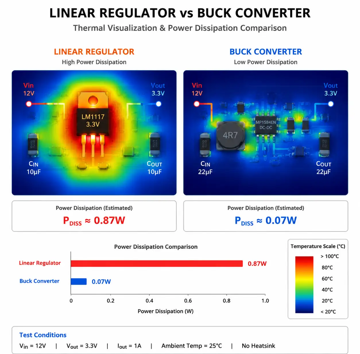
Thermal comparison between buck converter and linear regulator power dissipation
Design Considerations for High-Efficiency Apps
Datasheet efficiency in production requires careful component selection, PCB layout, and operating point optimization.
Inductor Selection: The inductor is the heart. Value sets ripple current: ΔIL = (Vin - Vout) × D / (L × fsw). Target 20-40% of max output current for best efficiency. Watch DC resistance and core losses at your frequency. Shielded types reduce EMI but have higher DCR. Saturation current must exceed peak inductor current (Iout + ΔIL/2) with 20% margin.
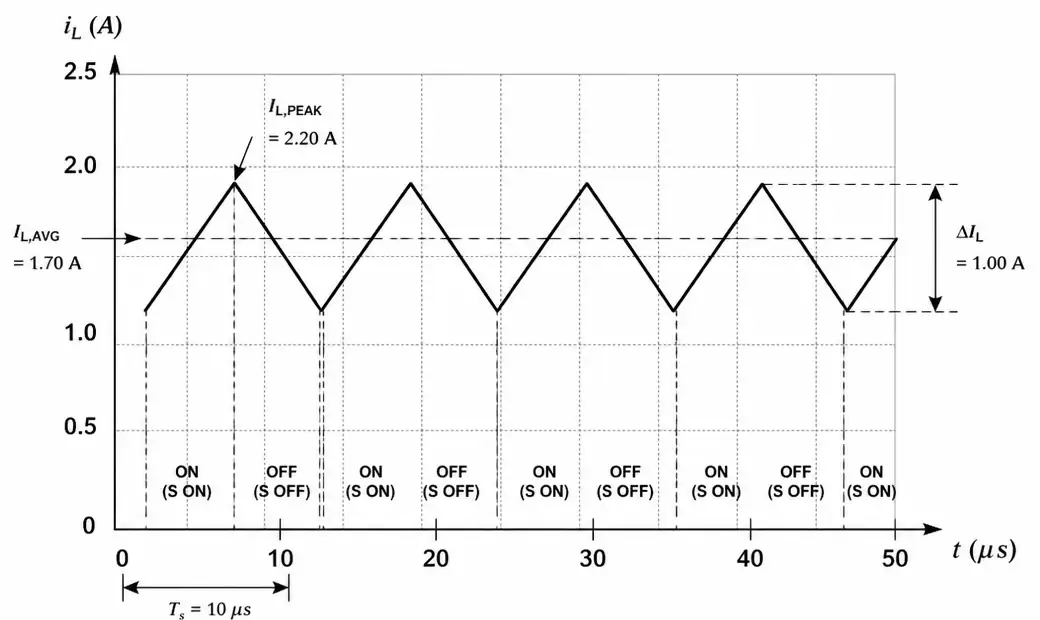
Buck converter inductor current waveform showing ripple current and DC component
Capacitor Selection: Input caps must handle high ripple current – use low-ESR ceramics (X7R/X5R). RMS input current: Icin(rms) = Iout × √(D × (1-D)). Output caps set ripple and transient response. Ripple has capacitive (ΔVc = ΔIL / (8 × fsw × Cout)) and ESR (ΔVesr = ΔIL × ESR) components. With ceramics, ESR is negligible.
PCB Layout: The high-current switching loop – input cap through switch node to inductor and back through ground – must be minimized. Keep loop area under 1 cm². Route feedback trace away from switching node to prevent coupling noise. Use continuous ground planes with separate high-current and low-current return paths joining at one point near the input cap.
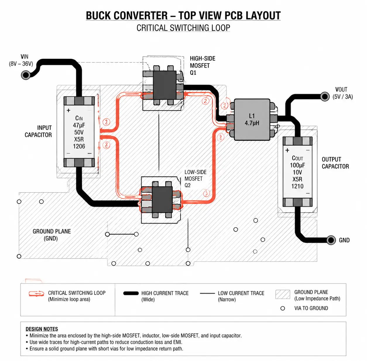
Buck converter PCB layout showing critical high-current switching loop
Common Design Mistakes and How to Avoid Them
| Error | Symptom | Root Cause | Fix |
|---|---|---|---|
| Excessive ripple | >200 mV ripple, audible noise | Insufficient Cout or poor layout | More Cout, shrink switching loop, add ceramics |
| Unstable output | Oscillation, ringing on load steps | Wrong compensation or feedback noise | Recalculate compensation, shield feedback trace |
| Poor light-load efficiency | High quiescent losses | Controller not entering pulse-skip | Pick converter with auto PFM/PWM transition |
| Thermal shutdown | Overheating in operation | Underestimated power dissipation | Verify efficiency at operating point, add thermal vias |
| Subharmonic oscillation | Ripple at fsw/2 | Insufficient slope comp with D>50% | Enable slope comp or reduce duty cycle |
| Start-up failure | Output fails to regulate | Insufficient input capacitance | Increase Cin, adjust soft-start |
A common trap: minimum on-time limits. With Vin much higher than Vout (e.g., 24V to 3.3V), duty cycle is small (3.3/24 = 13.75%). If min on-time is 150 ns at 1 MHz, min duty is 15% – causing pulse-skipping and high ripple. Fix: lower switching frequency, pick a controller with shorter min on-time, or use two-stage conversion.
Another frequent issue: inductor saturation during load steps. A sudden 0A to 5A step can push peak current past saturation, collapsing inductance and causing voltage droop. Always scope transient response under worst-case load steps.
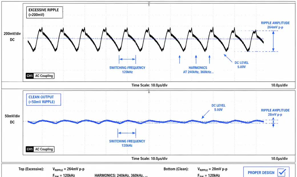
Output voltage ripple waveform showing excessive ripple due to design error
FAQ
What's the difference between synchronous and non-synchronous buck converters?
Non-synchronous uses a Schottky diode as the freewheeling element; synchronous replaces it with a MOSFET. Sync converters offer 3-10% higher efficiency at high output currents because MOSFET on-resistance beats diode forward drop. They cost more and need dead-time control to prevent shoot-through. Pick sync for battery-powered apps where efficiency is critical; non-sync for cost-sensitive, low-current designs.
How do I calculate inductor value for my buck converter?
Start with desired ripple current (20-40% of max Iout). Formula: L = (Vin - Vout) × Vout / (Vin × ΔIL × fsw). Example: Vin=12V, Vout=5V, Iout=2A, fsw=500kHz, 30% ripple (ΔIL=0.6A): L = (12-5) × 5 / (12 × 0.6 × 500k) = 9.7 µH. Pick nearest standard (10 µH) with saturation current ≥ (2A + 0.3A) × 1.2 = 2.8A.
Can I use buck converters in automotive apps?
Yes – but automotive brings wide input ranges (6V-40V for 12V systems), load-dump transients (up to 100V), and strict EMC (CISPR 25). Pick AEC-Q100 parts with Vin ≥ 45V and integrated transient protection. Use shielded inductors, input filtering, and follow automotive layout guidelines. Consider spread-spectrum modulation to cut EMI.
What causes audible noise in buck converters?
Audible noise (1-20 kHz) usually comes from ceramic capacitor piezoelectric effects or inductor magnetostriction. When switching frequency or subharmonics fall in the audio band, output ripple makes caps physically vibrate. Fixes: switch to >25 kHz, use polymer caps instead of ceramics, mount caps with flexible adhesive, pick inductors with bonded cores, or use spread-spectrum to spread acoustic energy.
What datasheet specs should I check first?
Priority list: abs max input voltage (must exceed worst-case transients with margin), output current at your operating temp (check derating curves), efficiency at your Vin/Vout/Iout point (not just peak), quiescent current in your operating mode, min on-time and max duty cycle (verify compatibility with your Vin/Vout ratio), and switching frequency options. Confirm control topology (voltage mode, current mode, or COT) fits your transient response and stability needs.
Conclusion
Selecting the right buck converter means balancing efficiency, cost, board space, and EMI while ensuring reliable operation across your input voltage range and load conditions. For high Vin/Vout ratios and loads above 500 mA, synchronous bucks beat linear regs on efficiency. Verify inductor saturation current exceeds peak current with 20% margin, caps meet RMS current with derating, min on-time supports your worst-case ratio, and layout minimizes the switching loop. For automotive or industrial, ensure AEC-Q100 and transient protection. Next steps: download datasheets and compare efficiency at your operating point, grab eval modules for top candidates, use manufacturer selection tools, and engage FAE early for mission-critical designs.
