


Common Mode Choke Selection Guide: How to Choose the Right Component for EMI Suppression
Table of Contents
- What is a Common Mode Choke and Why It Matters
- Key Technical Parameters Explained
- How to Select the Right Common Mode Choke for Your Application
- Performance Comparison by Application
- Design Considerations and Common Pitfalls
- Supply Chain and Sourcing Considerations
- FAQ
- Conclusion and Next Steps
1. What is a Common Mode Choke and Why It Matters
A common mode choke is a passive electromagnetic interference (EMI) filter component designed to suppress common mode noise while allowing differential mode signals to pass through with minimal attenuation. In practical terms, it prevents high-frequency noise currents that flow in the same direction on both signal lines from radiating or coupling into sensitive circuits.
Common mode chokes are essential in modern electronic designs because regulatory standards like FCC Part 15, CISPR 32, and EN 55032 require strict limits on conducted and radiated emissions. Without proper common mode filtering, products can fail EMC testing, delaying market entry and increasing compliance costs. In high-speed digital interfaces such as USB, HDMI, Ethernet, and CAN bus, common mode chokes protect signal integrity while ensuring that the system meets electromagnetic compatibility requirements.
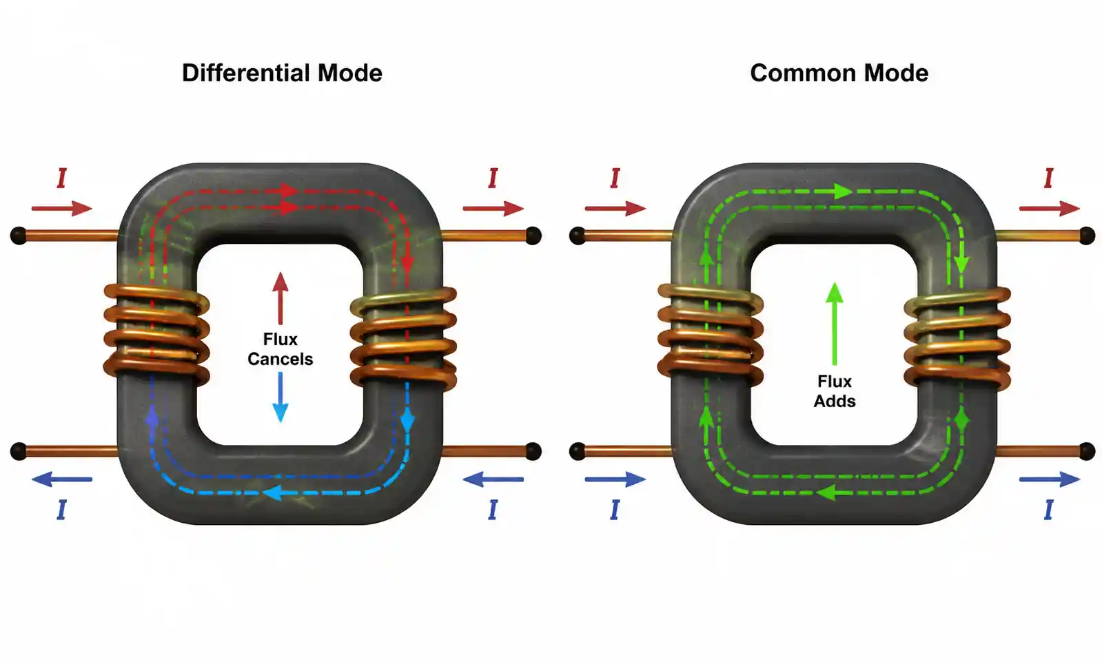
The core design of a common mode choke consists of two or more windings wound on a common magnetic core, typically ferrite or powdered iron. When differential mode signals pass through the component, the magnetic fields cancel out, resulting in low impedance and minimal signal degradation. However, when common mode currents flow, the magnetic fields add constructively, creating high impedance that blocks unwanted noise. This behavior makes common mode chokes fundamentally different from differential mode inductors, where both windings contribute to signal filtering.
In practical applications, engineers must balance several competing requirements: adequate common mode impedance across the frequency range of interest, low differential mode insertion loss to preserve signal quality, sufficient current handling capability, compact footprint for dense PCB layouts, and cost-effectiveness for high-volume production. Understanding these trade-offs is essential for successful component selection.
2. Key Technical Parameters Explained
Selecting the right common mode choke requires understanding the critical parameters that appear in datasheets. Each specification has direct implications for circuit performance, and misinterpreting these values is a common source of design errors.
Common Mode Impedance (Zcm)
Common mode impedance is the primary performance metric for a common mode choke. It represents the opposition to common mode currents at a specific frequency, typically measured at 25 MHz or 100 MHz. Higher impedance provides better noise suppression, but the impedance curve varies significantly with frequency due to parasitic capacitance and core material characteristics. When evaluating datasheets, always check the impedance value at the frequency where your EMI issue occurs, not just the headline specification.
Rated Current (Idc)
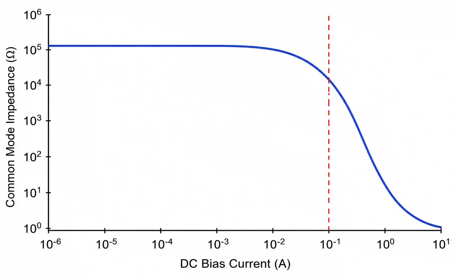
The DC current rating indicates the maximum continuous current the choke can handle before saturation reduces its effectiveness. Exceeding this rating causes the magnetic core to saturate, dramatically reducing common mode impedance. In power delivery applications like USB charging or PoE, engineers often mistakenly select chokes based only on impedance, only to discover that the component saturates under normal operating current. Always verify that the rated current exceeds the maximum expected load current with adequate margin.
[IMG_2]
Differential Mode Insertion Loss
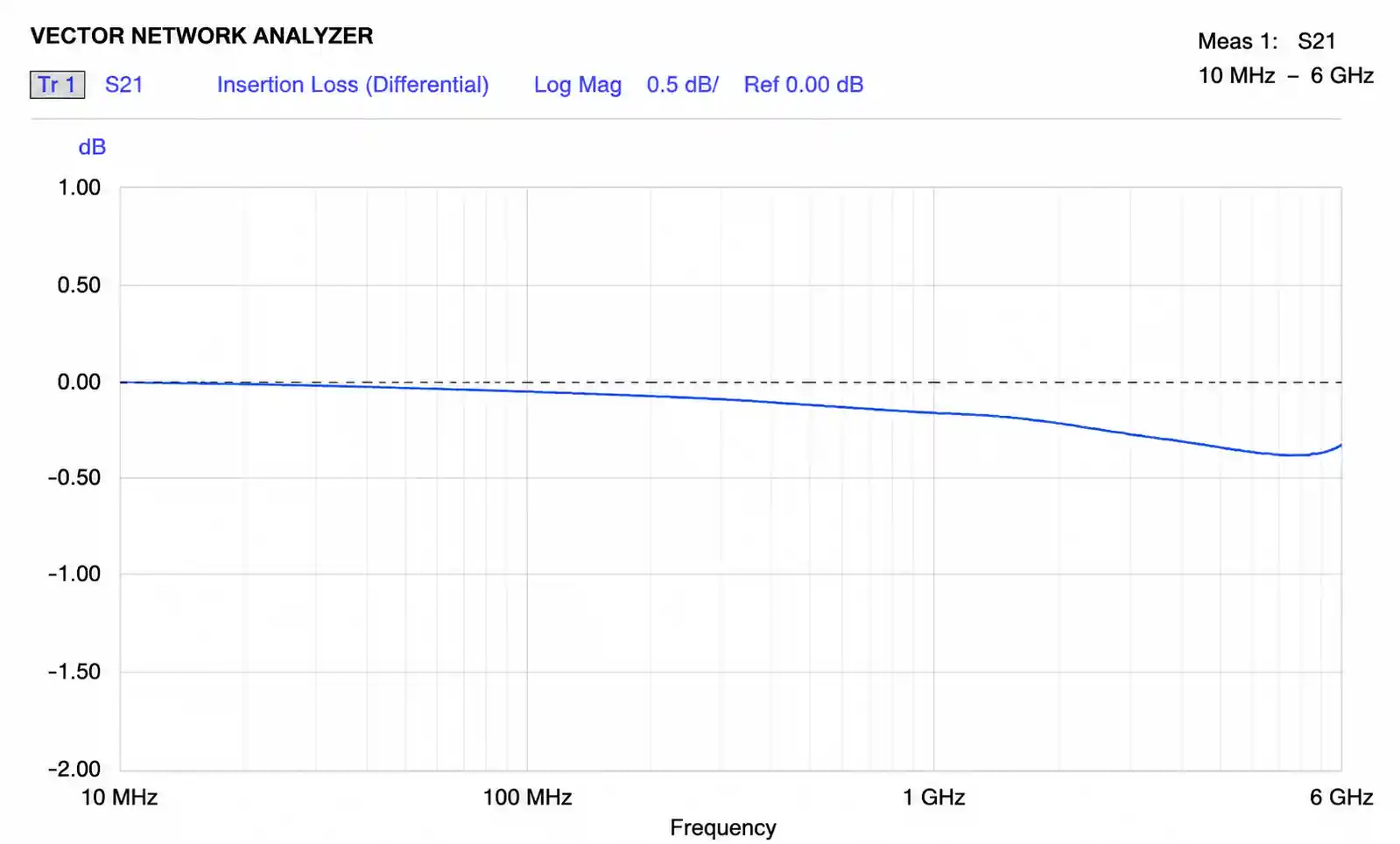
While common mode chokes are designed to block common mode noise, they inevitably introduce some insertion loss to differential signals. For high-speed data interfaces, excessive differential mode loss can cause signal integrity issues, leading to bit errors or link failures. The key design challenge is achieving sufficient common mode impedance without degrading the differential signal. In USB 3.0 and Ethernet applications, differential mode insertion loss should typically remain below 0.5 dB at the signal frequency to maintain acceptable performance.
Parasitic Capacitance
Inter-winding capacitance and winding-to-core capacitance create unwanted low-impedance paths at high frequencies. This parasitic capacitance limits the effective frequency range of the choke, causing impedance to roll off above a certain frequency. In designs targeting suppression above 500 MHz, such as HDMI 2.1 or USB4, low parasitic capacitance becomes critical. Datasheets often specify interwinding capacitance, which should be minimized for high-frequency applications.
Leakage Inductance
Leakage inductance represents the portion of inductance that does not couple magnetically between windings. While common mode chokes are designed for tight coupling, some leakage is unavoidable. Excessive leakage inductance can cause differential mode signal distortion, particularly in high-speed digital interfaces. For gigabit Ethernet and USB applications, leakage inductance should typically be below 1 µH to avoid signal quality degradation.
3. How to Select the Right Common Mode Choke for Your Application
Selecting a common mode choke involves a systematic methodology that considers both EMI performance requirements and signal integrity constraints. The following approach has been validated across automotive, industrial, and consumer electronics applications.
Step 1: Identify the Frequency Range of Interest
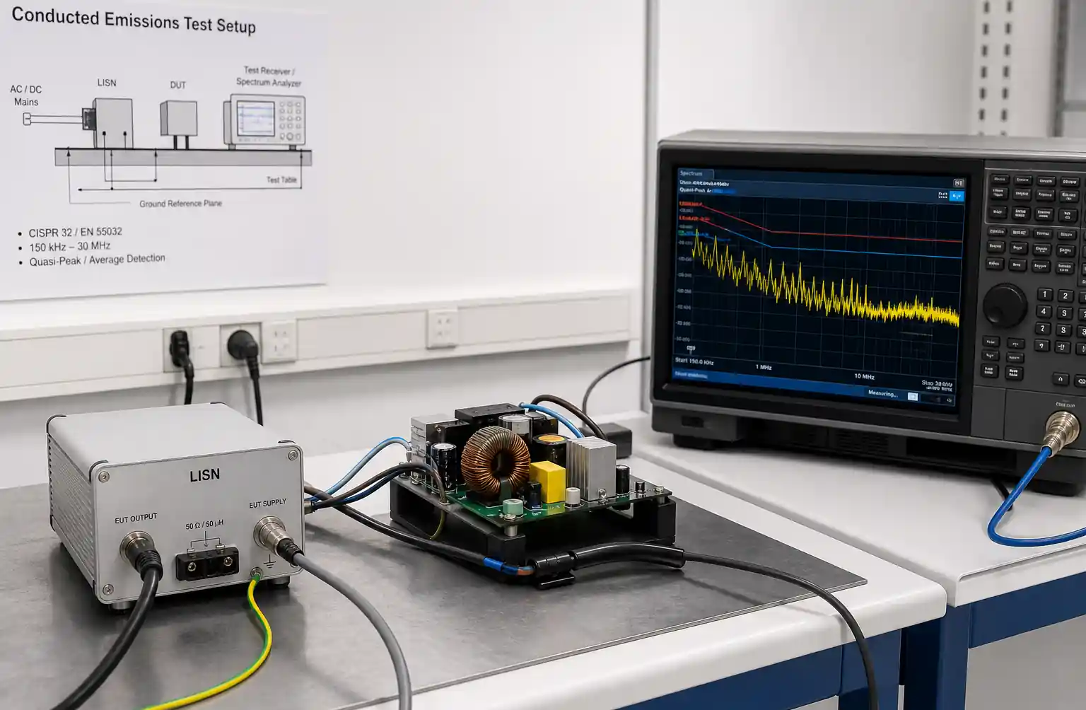
Begin by determining where your EMI issue occurs. Conducted emissions typically span 150 kHz to 30 MHz, while radiated emissions extend from 30 MHz to several GHz. Use pre-compliance testing or simulation to identify the frequency bands where noise exceeds regulatory limits. The common mode choke must provide adequate impedance across this entire range, not just at a single test frequency.
Step 2: Calculate Required Common Mode Impedance
The required impedance depends on the noise current magnitude and the acceptable attenuation level. A general guideline is that each doubling of impedance provides approximately 6 dB of additional suppression. For example, if your noise margin is -15 dB and you need to achieve a +5 dB margin, you require approximately 20 dB of attenuation, corresponding to a 10× impedance increase. This calculation should be performed at the frequency where the worst-case EMI occurs.
Step 3: Verify Current Rating and Saturation Characteristics
Measure or calculate the maximum DC current flowing through the choke under all operating conditions, including transient events. Select a component with a rated current at least 20% higher than this maximum to prevent saturation. For applications with large current swings, such as USB power delivery, review the inductance versus DC current curve in the datasheet to ensure that common mode impedance remains adequate even under peak load conditions.
Step 4: Evaluate Differential Mode Performance
For signal interfaces, verify that differential mode insertion loss remains acceptable across the signal bandwidth. Request S-parameter data from the manufacturer if available, or perform measurements using a vector network analyzer. Pay particular attention to return loss, which indicates impedance matching. Poor return loss can cause reflections that degrade signal quality even if insertion loss appears acceptable.
Step 5: Consider PCB Layout and Package Constraints
Package size, mounting style, and pin configuration affect both electrical performance and manufacturability. Surface mount components simplify automated assembly but may have higher parasitic capacitance than through-hole alternatives. In space-constrained designs, compact packages are attractive, but smaller components often have lower current ratings and reduced impedance. Always verify that the selected footprint is compatible with your PCB stackup and assembly process.
| Selection Criteria | Priority for High-Speed Data | Priority for Power Lines | Priority for Automotive CAN |
|---|---|---|---|
| Common mode impedance at 100 MHz | High | Medium | High |
| Differential mode insertion loss | Critical | Low | High |
| Current rating | Medium | Critical | Medium |
| Operating temperature range | Medium | High | Critical |
| ESD protection | High | Medium | Critical |
| Package size | Medium | Low | Medium |
This table illustrates how parameter priorities shift depending on the application. High-speed data interfaces demand minimal differential mode loss, power line filtering prioritizes current handling, and automotive applications require extended temperature range and robust ESD protection. Blindly selecting a choke based solely on common mode impedance without considering these application-specific factors is a common design mistake.
4. Performance Comparison by Application
Different applications impose distinct requirements on common mode chokes. The following comparison helps engineers match component characteristics to their specific use case.
| Application | Frequency Range | Typical Impedance | Rated Current | Key Challenge | Recommended Core Material | |---|---|---|---|---| | USB 2.0 / 3.0 | 10 MHz - 1 GHz | 100 - 600 Ω @ 100 MHz | 0.5 - 3 A | Maintaining signal integrity | Ni-Zn ferrite | | Gigabit Ethernet | 1 MHz - 500 MHz | 200 - 1000 Ω @ 100 MHz | 0.35 - 1 A | Low differential mode loss | Mn-Zn ferrite | | HDMI 2.0 / 2.1 | 100 MHz - 6 GHz | 50 - 300 Ω @ 1 GHz | 0.25 - 0.5 A | Ultra-low capacitance | Ni-Zn ferrite | | Power supply AC input | 150 kHz - 30 MHz | 1000 - 5000 Ω @ 1 MHz | 3 - 20 A | High current, no saturation | Mn-Zn or nanocrystalline | | CAN bus (automotive) | 1 MHz - 100 MHz | 200 - 800 Ω @ 100 MHz | 0.5 - 2 A | Temperature stability, ESD | Ni-Zn ferrite | | Industrial RS-485 | 1 MHz - 50 MHz | 300 - 1000 Ω @ 10 MHz | 0.25 - 1 A | Robust against transients | Mn-Zn ferrite |
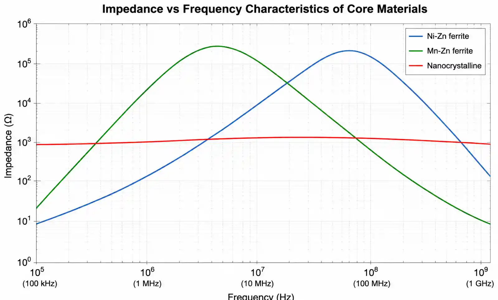
The choice of core material significantly impacts frequency response and temperature stability. Ni-Zn ferrite materials offer high impedance at frequencies above 50 MHz and low parasitic capacitance, making them ideal for high-speed digital interfaces. However, they have limited current handling capability due to lower saturation flux density. Mn-Zn ferrite provides better performance at lower frequencies (1-50 MHz) and higher current ratings, but exhibits higher core losses above 100 MHz. For power line filtering where high current is essential, nanocrystalline cores offer excellent saturation characteristics but at significantly higher cost.
In USB 3.0 applications, a typical design might use a common mode choke with 300 Ω at 100 MHz and 1 A current rating. This provides adequate EMI suppression while maintaining differential mode insertion loss below 0.3 dB up to 5 GHz, ensuring reliable SuperSpeed data transmission. Contrast this with an Ethernet application, where 500 Ω at 100 MHz is often required to meet CISPR 32 Class B limits, but the lower data rate allows slightly higher insertion loss tolerance.
5. Design Considerations and Common Pitfalls
Even experienced engineers make mistakes when integrating common mode chokes. The following issues represent the most frequent problems encountered during EMC testing and production.
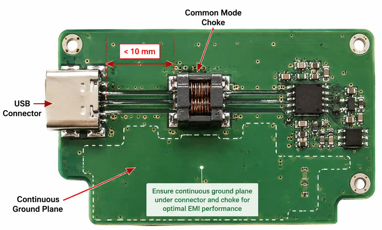
PCB Layout Errors
Placing the common mode choke too far from the connector or cable attachment point significantly reduces its effectiveness. Common mode currents can radiate from PCB traces before reaching the filter component. Best practice is to position the choke within 10 mm of the connector, with no ground plane discontinuities between them. Additionally, avoid routing high-frequency signals near the choke, as capacitive coupling can create new EMI paths that bypass the filter.
Ignoring Saturation Effects
Many designs fail EMC testing under high current conditions because engineers select chokes based only on the nominal operating current. Transient events, inrush currents, and fault conditions can temporarily drive the component into saturation. When the core saturates, common mode impedance drops dramatically, sometimes by 10-20 dB, eliminating the intended filtering effect. Always verify performance under worst-case current conditions, not just typical load.
Mismatched Impedance
In high-speed differential interfaces, the common mode choke must not disrupt the characteristic impedance of the transmission line. Discontinuities cause reflections that degrade signal quality and reduce the effective data rate. The differential mode impedance of the choke should match the line impedance (typically 90 Ω for USB, 100 Ω for Ethernet). This requires careful selection of leakage inductance and mounting geometry to maintain impedance continuity.
Inadequate Frequency Coverage
A common mistake is selecting a choke with excellent impedance at the test frequency (e.g., 100 MHz) but poor performance at the actual problem frequency. EMI emissions rarely occur at a single frequency; they typically appear as broadband noise or harmonics spanning a wide range. Always review the impedance versus frequency curve to ensure adequate suppression across the entire band where your noise exceeds limits. A component with 600 Ω at 100 MHz but only 50 Ω at 30 MHz may not solve a conducted emissions issue at the lower frequency.
Neglecting Temperature Effects
Core permeability and thus common mode impedance vary with temperature. Ni-Zn ferrite materials typically exhibit 20-30% impedance reduction at 85°C compared to 25°C. In automotive or industrial environments where operating temperatures reach 105°C or higher, this degradation must be factored into the design margin. Some engineers discover during thermal testing that their EMC margin disappears at elevated temperatures, requiring costly redesign.
| Common Mistake | Consequence | How to Avoid |
|---|---|---|
| Choke placed >20 mm from connector | Reduced EMI suppression | Position within 10 mm of connector |
| Selected based only on @25°C impedance | Fails EMC at high temperature | Verify impedance at max operating temp |
| Insufficient current rating margin | Saturation under peak load | Use 20-30% current margin minimum |
| Ignored differential mode loss | Signal integrity issues, BER increase | Check S21 parameters across signal BW |
| Single-frequency impedance check | Narrow-band filtering, EMI persists | Review full impedance curve 1-1000 MHz |
6. Supply Chain and Sourcing Considerations
Beyond technical specifications, practical considerations around availability, cost, and second-sourcing impact component selection, especially in high-volume production.
Lead Time and Availability
Common mode chokes, particularly those with specialized core materials or high current ratings, often have lead times of 12-16 weeks or longer. During periods of component shortages, lead times can extend to 26+ weeks. Engineers should identify multiple qualified sources during the design phase rather than waiting until production ramp-up. Check distributor stock levels for the specific part number, not just the product family, as availability varies significantly even within a single manufacturer's lineup.
Cost Versus Performance Trade-offs
Premium common mode chokes with nanocrystalline cores or ultra-low capacitance construction can cost 3-5× more than standard ferrite designs. In cost-sensitive consumer electronics, the component cost must be justified by either reduced board area, elimination of additional filter stages, or improved EMC margin that reduces compliance risk. Performing a total cost analysis that includes PCB real estate, assembly labor, and EMC testing iterations often reveals that a more expensive component delivers lower overall program cost.
Qualification and Reliability
For automotive, medical, and industrial applications, component qualification extends beyond electrical specifications to include mechanical stress testing, humidity resistance, thermal cycling, and long-term reliability validation. AEC-Q200 qualification for automotive components typically adds 6-8 weeks to initial sampling schedules and increases component cost by 20-40%. However, this qualification significantly reduces field failure risk and is often mandated by tier-1 automotive customers.
Second-Source Strategies
Relying on a single manufacturer for common mode chokes creates supply chain risk. Ideally, qualify at least two component sources with similar electrical characteristics. Pay attention to footprint compatibility, as different manufacturers may use slightly different pin spacing even for nominally equivalent components. When evaluating alternatives, compare not just the headline specifications but also the full impedance curve, temperature coefficients, and saturation characteristics to ensure true equivalence.
7. FAQ
What is the difference between common mode and differential mode chokes?
Common mode chokes suppress noise currents flowing in the same direction on both conductors, while differential mode chokes filter currents flowing in opposite directions. Structurally, common mode chokes have tightly coupled windings wound on a shared core, causing differential signals to cancel magnetically while common mode currents add. In contrast, differential mode inductors use separate cores or loosely coupled windings to block both signal polarities equally.
How do I calculate the required common mode impedance for my application?
Start by measuring the noise current magnitude at the frequency where EMI limits are exceeded. The required impedance equals the voltage drop needed to attenuate this current to acceptable levels. As a rule of thumb, each 10× increase in impedance provides approximately 20 dB of suppression. For example, if your margin is -10 dB at 100 MHz, adding a choke with 500 Ω impedance typically provides 15-20 dB improvement, assuming 25-50 Ω source impedance.
Can I use a common mode choke in automotive applications (AEC-Q200)?
Yes, but you must select components specifically qualified to AEC-Q200 standards. These parts undergo additional testing including high-temperature operating life (HTOL), temperature cycling, mechanical shock, and humidity resistance. Not all common mode chokes carry automotive qualification, so verify the datasheet explicitly states AEC-Q200 compliance. Additionally, automotive applications often require extended temperature ranges (-40°C to +125°C) and higher ESD robustness (IEC 61000-4-2 Level 4).
What causes common mode choke saturation and how can I prevent it?
Saturation occurs when the magnetic core's flux density reaches its maximum limit, typically caused by excessive DC current. Once saturated, the core permeability drops dramatically, reducing common mode impedance by 80-90%. Prevent saturation by selecting a choke with rated current 20-30% above your maximum operating current, including transients. Some designs use cores with an air gap to increase saturation resistance, though this reduces initial impedance.
How do I handle long lead times for specialized common mode chokes?
For critical designs with extended lead times, consider these strategies: forecast demand and place advance orders based on projected volumes; qualify multiple suppliers during design phase to enable quick pivots; design with more readily available components even if slightly over-specified; maintain buffer stock for production ramp-up; engage distributors early for allocation commitments. In some cases, redesigning the filter network to use more common component values reduces supply risk.
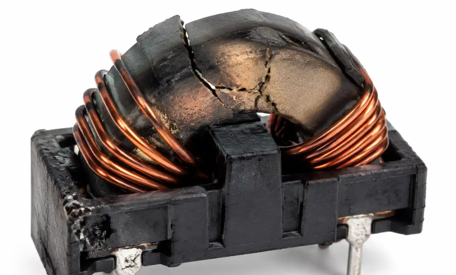
What are common failure modes for common mode chokes?
The most frequent failure modes include thermal damage from overcurrent (visible as discolored or cracked ferrite), mechanical fracture from PCB flexure or shock (automotive environments), and winding opens from solder joint fatigue. Proper derating (current, temperature) and mechanical strain relief minimize these risks. Additionally, ESD events can cause inter-winding shorts, so designs with high ESD exposure should include upstream protection diodes.
Is there a pin-compatible alternative if my chosen part becomes obsolete?
Pin compatibility depends on package standardization. Many manufacturers follow industry-standard footprints for common packages (0805, 1206, etc.), enabling drop-in replacement. However, electrical parameters vary significantly even among physically compatible parts. When a component approaches end-of-life, immediately cross-reference impedance curves, current ratings, and temperature performance with alternatives. Perform EMC regression testing with the replacement part before committing to production use, as subtle differences can affect margins.
8. Conclusion and Next Steps
Selecting the right common mode choke requires balancing EMI suppression requirements, signal integrity constraints, current handling capability, and supply chain considerations. The most critical factors are ensuring adequate common mode impedance across the entire problem frequency range, preventing saturation under worst-case current conditions, and maintaining acceptable differential mode performance for signal interfaces.
If your application involves high-speed data transmission (USB 3.0+, Gigabit Ethernet, HDMI), prioritize low differential mode insertion loss and minimal parasitic capacitance. For power line filtering, focus on high current ratings and wide frequency coverage from 150 kHz to 30 MHz. Automotive and industrial designs require extended temperature qualification and robust ESD protection.
Before finalizing your component selection, verify the following: impedance curve meets requirements at operating temperature, current rating exceeds peak load with adequate margin, differential mode insertion loss is acceptable across signal bandwidth, footprint is compatible with your PCB layout and assembly process, and at least one qualified second source is available.
For detailed technical specifications and application notes, download the full datasheet from the manufacturer. If you need assistance with EMC compliance testing or custom filter design, contact a field application engineer who can provide reference designs and simulation models specific to your use case. Many distributors also offer online selection tools that filter components based on your electrical requirements, simplifying the initial screening process.