




Current Sensing Resistor Selection: Shunt Resistors for Precision Measurement
Accurate current measurement is fundamental to power management, battery monitoring, and motor control systems. Studies show that improper shunt resistor selection accounts for over 30% of current-sensing circuit failures in industrial and automotive applications. After evaluating hundreds of current-sensing designs across battery management systems, motor drives, and power supplies, I've seen how resistance value miscalculations, inadequate power ratings, and poor TCR specifications lead to measurement drift exceeding ±5% under thermal stress.
This guide provides a structured approach to selecting current-sensing resistors based on measurement accuracy requirements, power dissipation limits, and temperature stability. You will learn how to calculate optimal resistance values, evaluate TCR impact, implement four-wire Kelvin sensing, and choose between low-side and high-side configurations for reliable precision measurement.
Table of Contents
- What Are Current Sensing Resistors
- Key Specifications for Shunt Resistor Selection
- Resistance Value Calculation
- Power Dissipation and Thermal Management
- Temperature Coefficient of Resistance (TCR) Impact
- Four-Wire Kelvin Sensing for Accuracy
- Low-Side vs High-Side Current Sensing
- Common Selection Mistakes
- FAQ
- Conclusion
What Are Current Sensing Resistors
Current sensing resistors, also called shunt resistors, are precision low-value resistors placed in series with the load to measure current flow. These resistors convert current into a proportional voltage drop that can be measured by instrumentation amplifiers or ADCs. The fundamental relationship follows Ohm's law: V = I × R, where the voltage drop across the shunt represents the current magnitude.
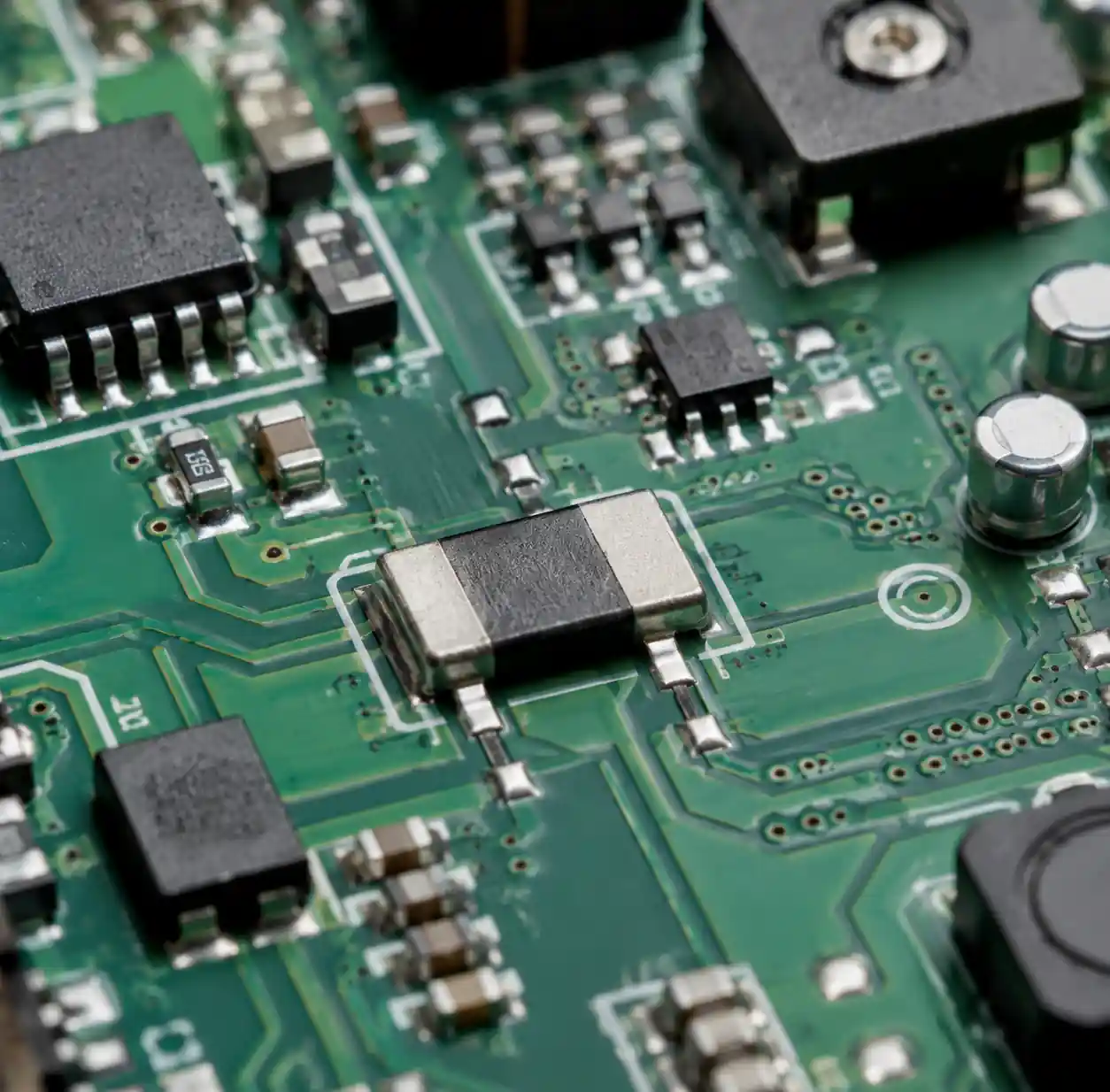 Current sensing resistor in power management circuit application
Unlike Hall-effect sensors or current transformers, shunt resistors provide DC and AC current measurement with excellent linearity, wide bandwidth (DC to MHz), and no magnetic hysteresis. Modern precision shunt resistors achieve tolerance as tight as ±0.1%, TCR below ±20 ppm/°C, and power ratings from 0.25W to over 5W in surface-mount packages.
You can use current sensing resistors in battery management systems for coulomb counting, motor control for torque feedback, power supplies for overcurrent protection, and automotive electronics for load monitoring per AEC-Q200 standards.
Key Specifications for Shunt Resistor Selection
Selecting the right shunt resistor requires evaluating multiple interdependent parameters. The five critical specifications determine measurement accuracy and system reliability.
| Specification | Typical Range | Impact on Performance |
|---|---|---|
| Resistance Value | 0.5 mΩ to 100 mΩ | Voltage drop vs signal level |
| Tolerance | ±0.1% to ±5% | Initial accuracy |
| TCR | ±20 to ±100 ppm/°C | Temperature stability |
| Power Rating | 0.25W to 5W | Maximum current capacity |
| Package Type | 2512, 2010, 4-terminal | PCB footprint and thermal |
Resistance value determines the voltage drop for a given current. Lower resistance minimizes power dissipation but reduces signal-to-noise ratio. Higher resistance provides better signal amplitude but increases power loss and heating.
Tolerance specifies the manufacturing accuracy of the nominal resistance value. Precision applications require ±1% or better. Industrial-grade applications function with ±5% tolerance when combined with calibration.
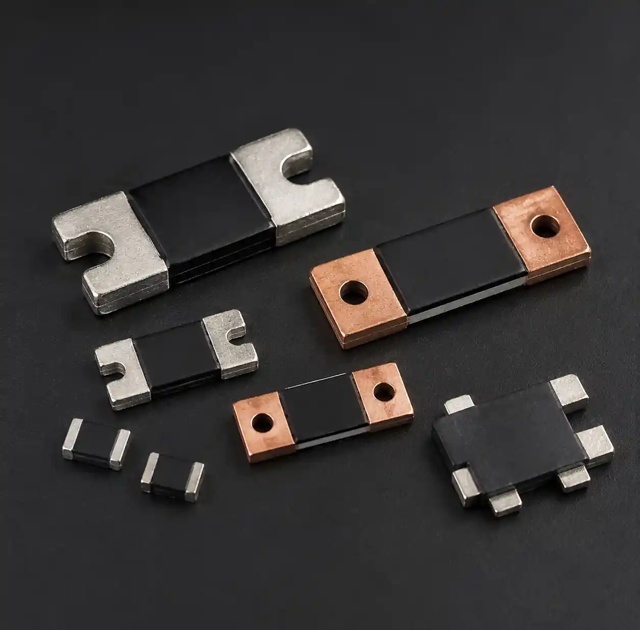 Shunt resistor key specifications and parameters
Temperature coefficient of resistance (TCR) quantifies how resistance changes with temperature, measured in ppm/°C. A shunt with 50 ppm/°C TCR will shift 0.5% over a 100°C temperature range, directly impacting measurement accuracy.
Power rating defines the maximum continuous power dissipation without exceeding temperature limits. Insufficient power rating causes thermal runaway and permanent resistance drift. You should specify resistors with 50-100% derating for reliability.
Resistance Value Calculation
Resistance value selection involves balancing three competing factors: voltage drop magnitude, power dissipation, and ADC/amplifier input range. The calculation starts with defining the maximum current to be measured (Imax) and the desired voltage drop (Vsense).
Basic resistance calculation:
Rshunt = Vsense / Imax
For a 10A maximum current with 100mV sense voltage:
Rshunt = 0.1V / 10A = 10 mΩ
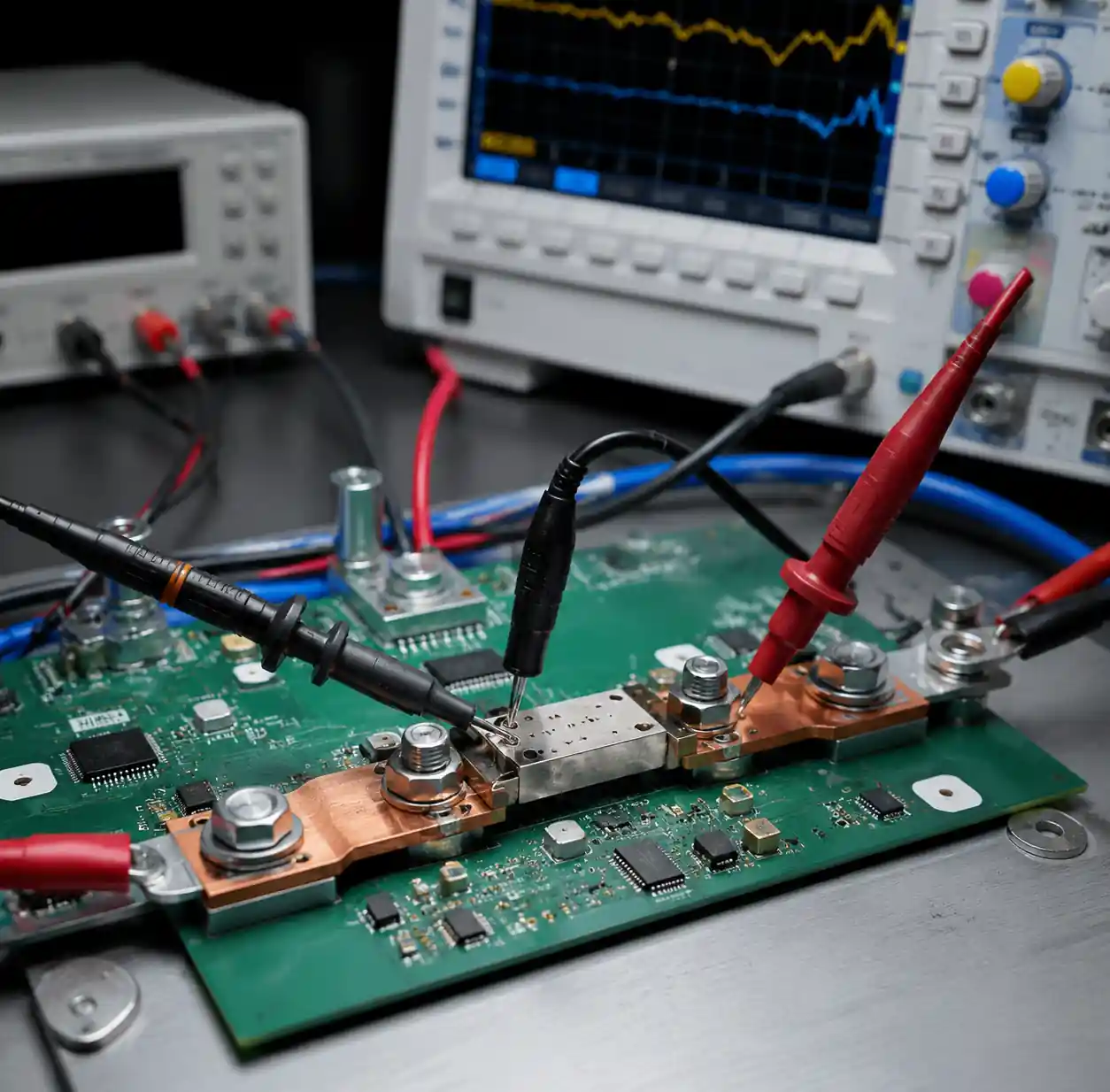 Current sensing circuit showing resistance value selection
Practical constraints limit the usable voltage drop range. For instrumentation amplifier inputs, 50-200mV provides optimal signal-to-noise ratio while staying within common-mode input limits. For direct ADC measurement, the voltage drop should match the ADC reference voltage range scaled by the expected measurement resolution.
Common voltage drop ranges by application:
- Battery monitoring: 50-75mV (minimizes power loss)
- Motor control: 100-150mV (balances SNR and dissipation)
- Power supply protection: 150-300mV (prioritizes fast detection)
- Precision instrumentation: 75-100mV (optimizes ADC resolution)
You must verify that the calculated resistance value is commercially available. Standard values for current-sense resistors include: 0.5mΩ, 1mΩ, 2mΩ, 5mΩ, 10mΩ, 20mΩ, 50mΩ, and 100mΩ. Selecting the nearest standard value simplifies procurement and reduces lead times.
Power Dissipation and Thermal Management
Power dissipation in the shunt resistor generates heat that affects both the resistor and surrounding components. Excessive temperature rise degrades measurement accuracy, accelerates component aging, and can cause catastrophic failure in extreme cases.
Power dissipation calculation:
P = I² × Rshunt
For a 10mΩ resistor carrying 10A:
P = (10A)² × 0.010Ω = 1W
| Current (A) | Rshunt | Power @ Imax | Required Rating |
|---|---|---|---|
| 5A | 10 mΩ | 0.25W | 0.5W (2× margin) |
| 10A | 10 mΩ | 1W | 2W (2× margin) |
| 20A | 5 mΩ | 2W | 3-4W (50-100% margin) |
| 50A | 2 mΩ | 5W | 7.5-10W (50-100% margin) |
Self-heating effect causes the resistor temperature to rise above ambient. This temperature increase changes the resistance value according to the TCR, introducing measurement error. For a 50 ppm/°C TCR and 50°C self-heating:
ΔR/R = 50 ppm/°C × 50°C = 2500 ppm = 0.25%
Thermal resistance (θJA) from junction to ambient determines temperature rise: ΔT = P × θJA
A 2512 SMD resistor typically has θJA = 120°C/W. At 1W dissipation:
ΔT = 1W × 120°C/W = 120°C rise
You should implement copper pours connected to both terminals to reduce thermal resistance. For high-power applications, specify larger packages (2512, 2010, or even TO-220 style) with lower θJA values. Adding thermal vias under the resistor footprint improves heat spreading into internal PCB copper layers.
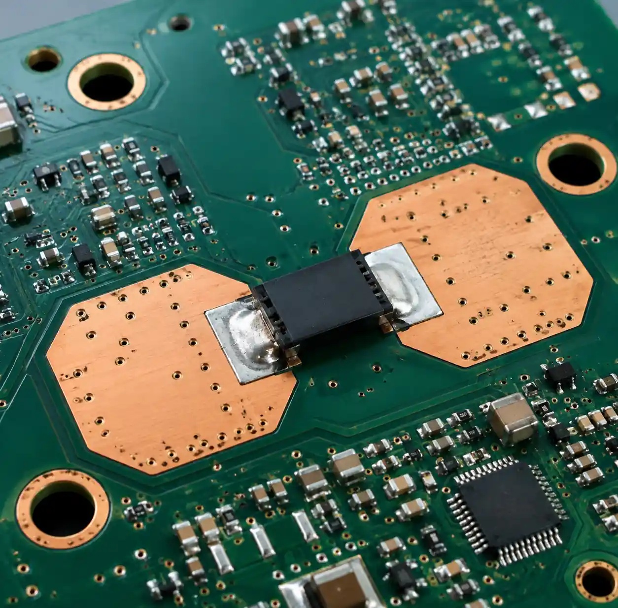 Shunt resistor thermal management with copper pour
Temperature Coefficient of Resistance (TCR) Impact
Temperature coefficient of resistance (TCR) quantifies how the resistance value shifts with temperature changes. This parameter directly determines measurement accuracy across the operating temperature range and represents a critical specification for precision current sensing.
TCR definition and calculation:
TCR = (R₂ - R₁) / [R₁ × (T₂ - T₁)]
Expressed in parts per million per degree Celsius (ppm/°C). A resistor with TCR of +50 ppm/°C increases resistance by 0.005% for each degree Celsius rise.
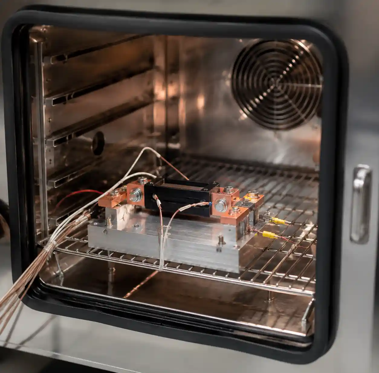 Temperature testing setup for shunt resistor TCR measurement
TCR categories for current-sense resistors:
- Ultra-precision: ±10 to ±20 ppm/°C (medical, metrology)
- Precision: ±25 to ±50 ppm/°C (automotive, industrial)
- Standard: ±75 to ±100 ppm/°C (consumer, cost-sensitive)
Practical TCR impact calculation:
For a system operating from -40°C to +125°C (165°C range) with a 50 ppm/°C TCR:
Total drift = 50 ppm/°C × 165°C = 8250 ppm = 0.825%
This 0.825% resistance change translates directly to current measurement error if not compensated. Combined with ±1% initial tolerance, total uncertainty reaches ±1.825% across temperature.
| TCR (ppm/°C) | Temp Range | Drift (%) | Application |
|---|---|---|---|
| ±20 | -40 to +125°C | ±0.33% | Battery management, precision |
| ±50 | -40 to +125°C | ±0.825% | Automotive, industrial control |
| ±100 | 0 to +85°C | ±0.85% | Consumer electronics |
| ±200 | 0 to +70°C | ±1.4% | Cost-optimized designs |
Temperature compensation strategies:
- Ratiometric measurement: Use the same reference for ADC and shunt measurement to cancel first-order TCR effects
- Software correction: Measure resistor temperature with a thermistor and apply correction factors
- Low-TCR resistors: Specify metal foil or thin-film technology with TCR below ±25 ppm/°C
You should specify TCR based on the required measurement accuracy budget. For ±1% total accuracy systems, use ±50 ppm/°C or better. For ±0.5% systems, specify ±25 ppm/°C TCR components.
Four-Wire Kelvin Sensing for Accuracy
Four-wire Kelvin sensing, also called 4-terminal or 4-point measurement, eliminates errors from lead resistance and PCB trace resistance by using separate current-carrying and voltage-sensing connections. This technique becomes essential for resistance values below 10 mΩ where trace resistance can exceed 1-2 mΩ per inch.
Standard 2-wire measurement limitations:
In conventional 2-wire sensing, the same connections carry load current and sense voltage. The voltage drop across PCB traces, solder joints, and contact resistance adds to the measured signal, causing systematic over-reading.
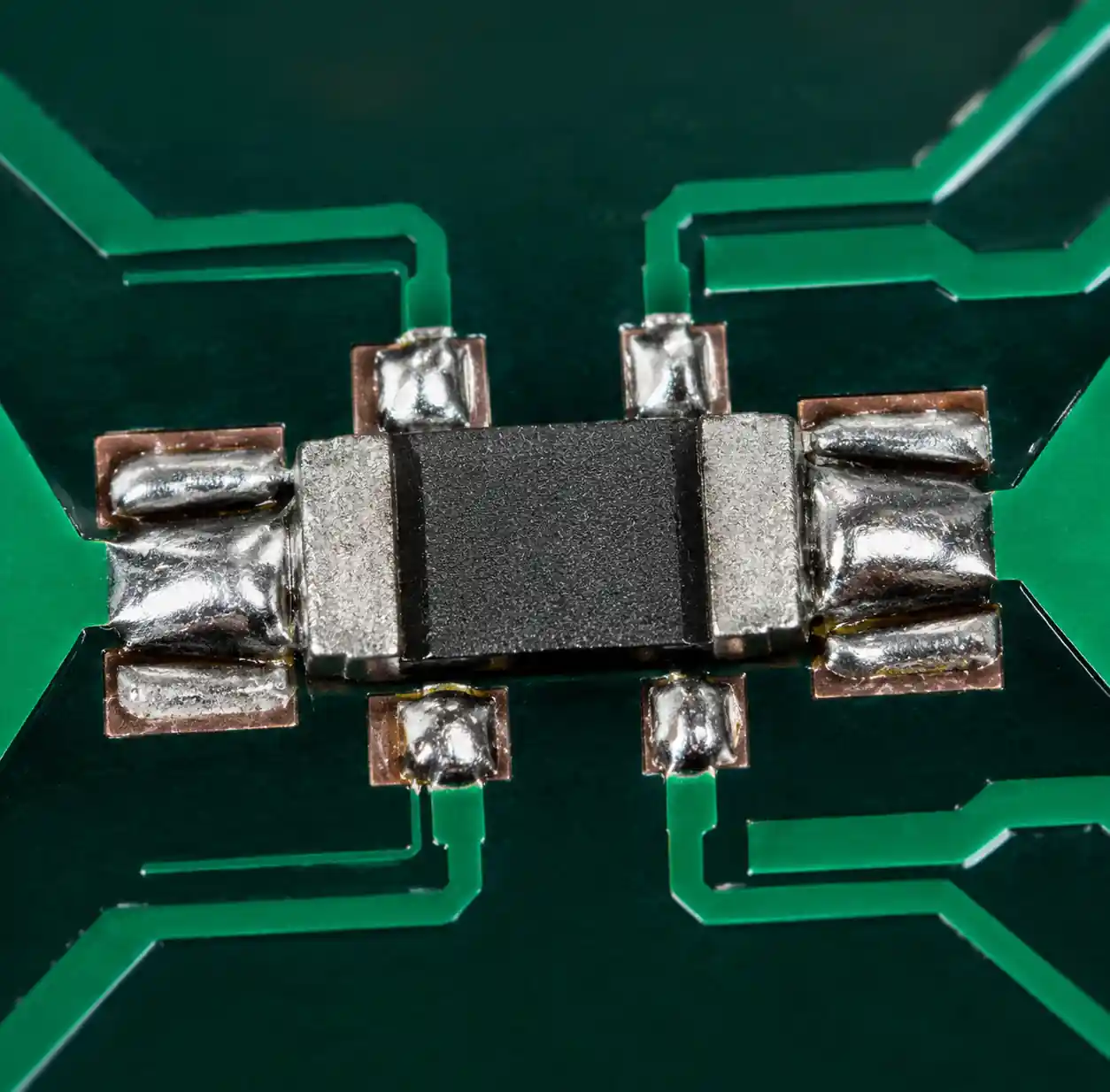 Four-wire Kelvin sensing connection on shunt resistor
For a 5 mΩ shunt with 10A current, trace resistance of just 1 mΩ introduces:
Error = 1mΩ / 5mΩ = 20% over-reading
Kelvin connection principle:
Four-wire sensing uses separate force (F+, F−) and sense (S+, S−) terminals. Load current flows through the force terminals while the voltage measurement uses the sense terminals, which carry negligible current. Since sense terminal current is typically <1 µA, voltage drop across lead resistance becomes insignificant.
| Measurement Method | Accuracy | Typical Error | Applications |
|---|---|---|---|
| 2-wire | ±5-20% | Trace resistance error | R > 50 mΩ, non-critical |
| 4-wire Kelvin | ±0.1-1% | TCR limited | R < 10 mΩ, precision |
| Kelvin + low-TCR | ±0.05-0.5% | Minimized | Calibration, metrology |
PCB layout requirements for Kelvin sensing:
- Route sense traces separately from current-carrying traces
- Connect sense traces directly to the resistor pads, not to the current path
- Keep sense trace impedance high (thin traces acceptable) to minimize loading
- Place sense connections as close as possible to the resistor body
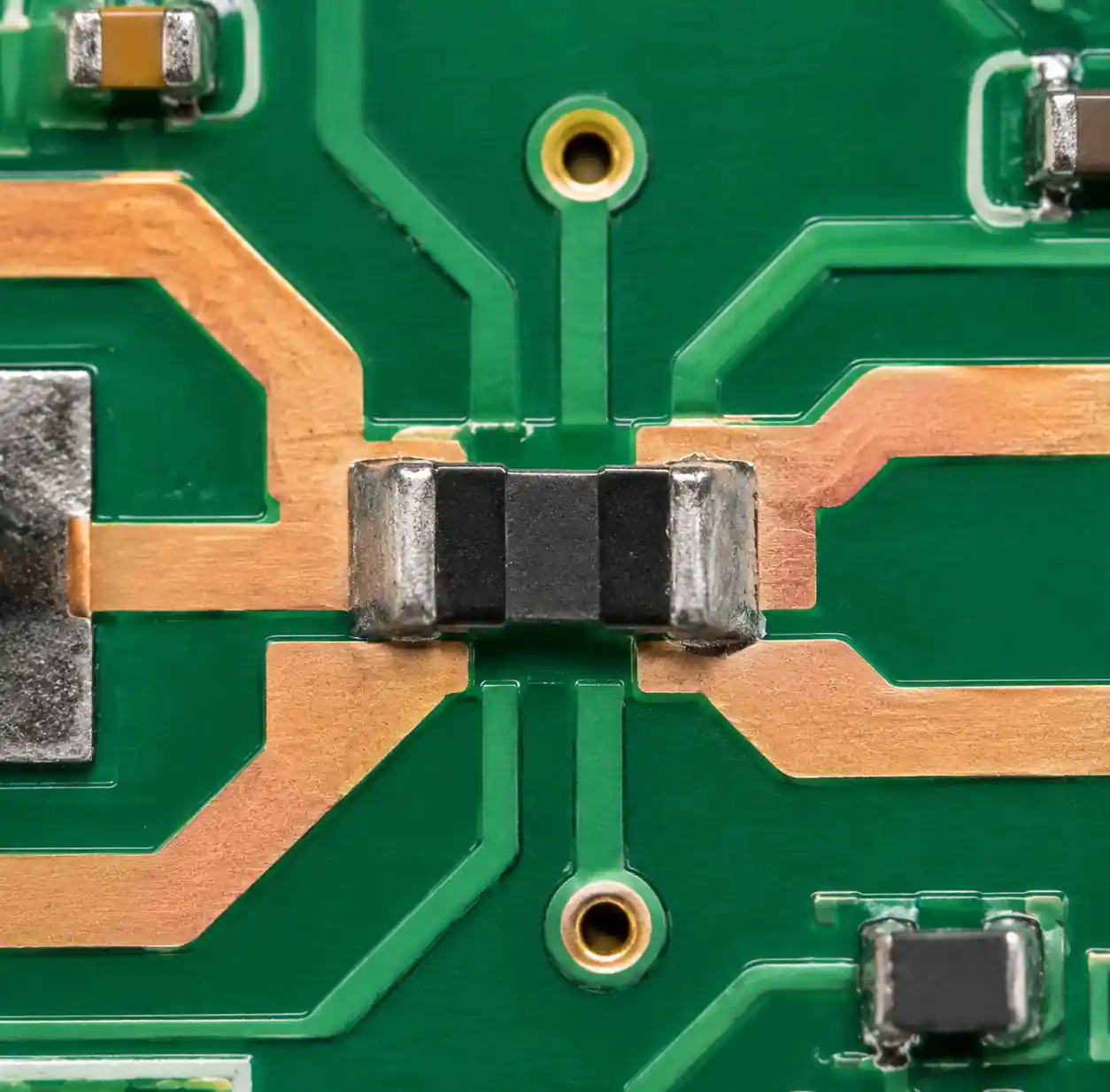 PCB layout showing proper Kelvin sensing trace routing
Four-terminal resistor packages provide dedicated Kelvin connections. These specialized components feature separate terminals for current and voltage, optimizing pad layout for minimum parasitic resistance. Common packages include 4-terminal 2512, 3920, and through-hole configurations.
PCB layout showing proper Kelvin sensing trace routing
Four-terminal resistor packages provide dedicated Kelvin connections. These specialized components feature separate terminals for current and voltage, optimizing pad layout for minimum parasitic resistance. Common packages include 4-terminal 2512, 3920, and through-hole configurations.
You should implement Kelvin sensing whenever shunt resistance falls below 10 mΩ or when accuracy requirements exceed ±1%. This technique is standard practice in battery management systems, motor control inverters, and precision power supplies.
Low-Side vs High-Side Current Sensing
Current-sensing resistor placement relative to the load and ground determines the circuit topology, common-mode voltage requirements, and fault detection capabilities. The choice between low-side and high-side sensing involves fundamental trade-offs in simplicity, safety, and diagnostic capability.
Low-side sensing places the shunt resistor between the load and ground (return path). The load connects to the positive supply rail, and current returns through the shunt to ground.
Advantages of low-side sensing:
- Simple voltage measurement (sense voltage near ground potential)
- No high common-mode voltage amplifier required
- Lower cost instrumentation (op-amps, ADCs)
- Easier PCB layout and routing
Disadvantages of low-side sensing:
- Disrupts ground reference for the load
- Cannot detect short-circuit to ground faults
- Load is not directly grounded (safety concern in some applications)
- Common-mode voltage varies with load voltage drop
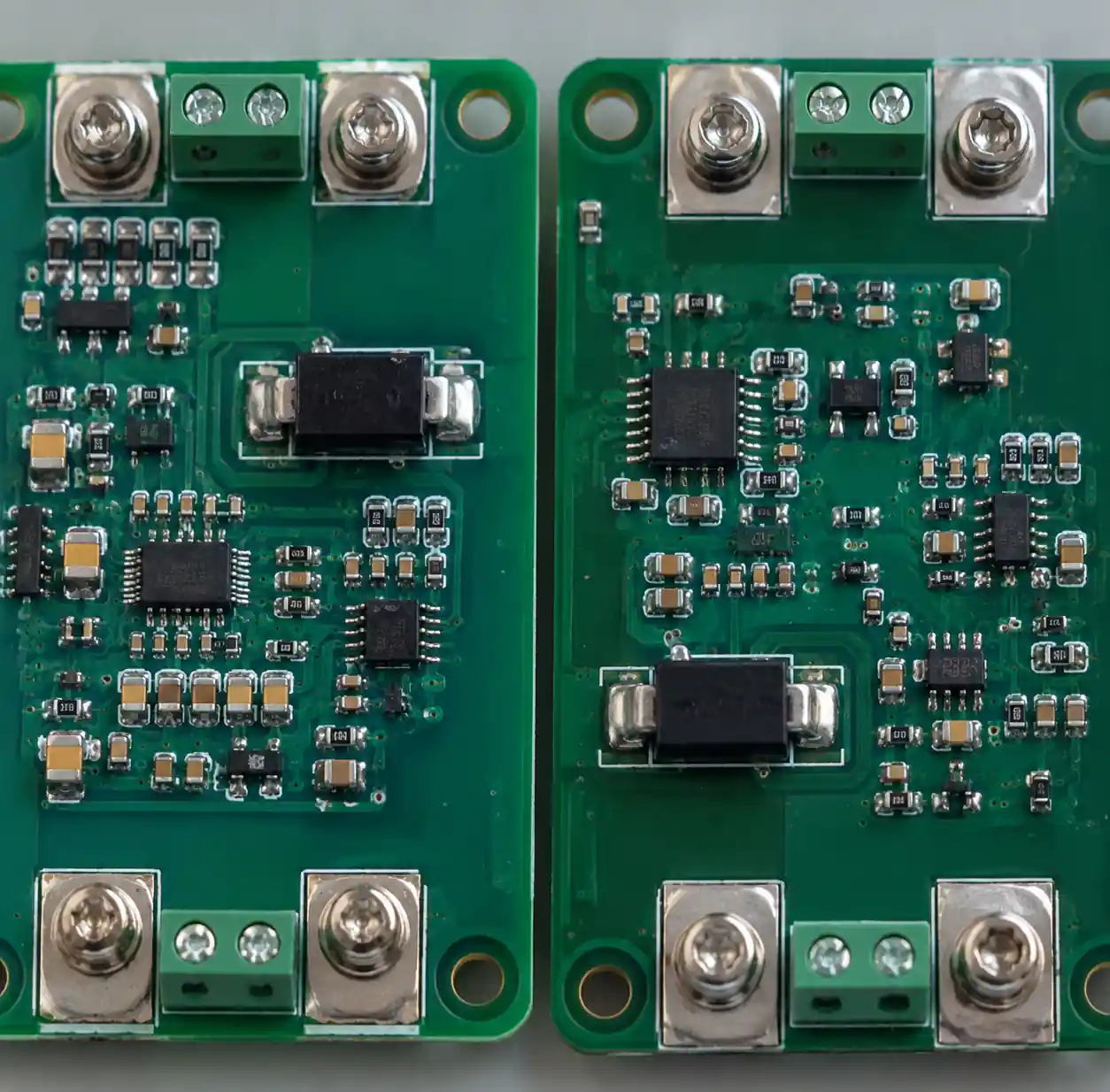 High-side and low-side current sensing circuit implementation
High-side sensing places the shunt resistor between the positive supply rail and the load. The load connects to ground through its return terminal.
Advantages of high-side sensing:
- Load remains grounded (preserves ground reference integrity)
- Detects short-circuit to ground faults
- Safer in automotive and industrial applications
- Measures supply-side current directly from source
Disadvantages of high-side sensing:
- Requires high common-mode voltage amplifier or differential ADC
- More expensive instrumentation components
- Common-mode voltage equals supply rail (can exceed 100V)
- More complex PCB design considerations
| Consideration | Low-Side Sensing | High-Side Sensing |
|---|---|---|
| Complexity | Simple | Complex (high CMRR amplifier) |
| Cost | Lower | Higher |
| Ground Integrity | Disrupted | Maintained |
| Fault Detection | Limited (no GND short detect) | Comprehensive |
| Safety | Adequate for low voltage | Required for automotive, industrial |
| Common-mode Voltage | ~0V | Supply voltage (up to 100V+) |
Application-specific recommendations:
- Low-side sensing: Suitable for power supplies, consumer electronics, lab instrumentation where ground disruption is acceptable and supply voltage is moderate (<48V)
- High-side sensing: Required for motor control, battery management, automotive systems per ISO 26262, industrial equipment where load grounding and fault detection are critical
You should choose high-side sensing for automotive and industrial applications to meet safety standards and enable comprehensive diagnostics. Specify low-side sensing for cost-sensitive consumer applications where the simpler circuitry reduces BOM costs by 30-50%.
Common Selection Mistakes
After reviewing hundreds of current-sensing designs, certain selection mistakes appear repeatedly and cause predictable field failures. Understanding these errors helps avoid costly redesigns and warranty claims.
Mistake 1: Inadequate power rating
Selecting a shunt resistor with power rating equal to calculated dissipation provides no thermal margin. Temperature rise degrades TCR performance and accelerates aging. Real-world load current can exceed nominal values during startup, transients, and fault conditions.
Solution: Specify resistors with 50-100% power derating. For 1W calculated dissipation, use a 2W or 3W rated component.
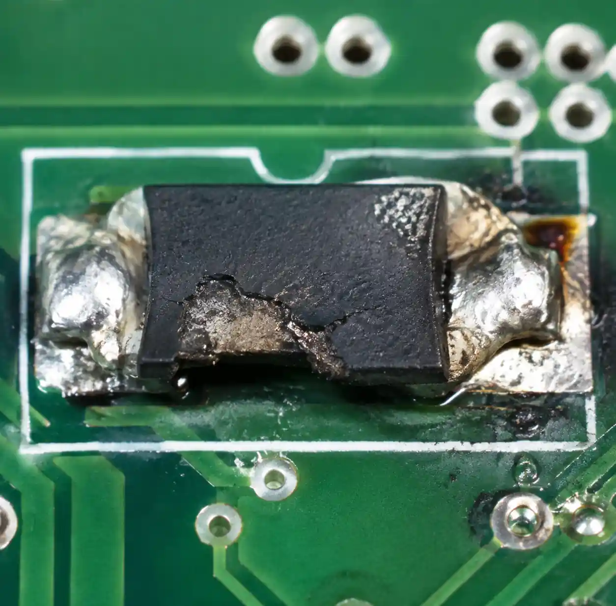 Damaged shunt resistor from insufficient power rating
Mistake 2: Ignoring self-heating and TCR interaction
Designers calculate power dissipation but fail to account for the resulting temperature rise and subsequent TCR-driven resistance shift. This creates a feedback loop where increased current causes heating, which changes resistance, which affects the measured current value.
Solution: Calculate self-heating temperature rise (ΔT = P × θJA) and multiply by TCR to quantify accuracy impact. For critical applications, use low-TCR resistors (±25 ppm/°C or better) with good thermal coupling to PCB copper.
Mistake 3: Using 2-wire sensing for low-value shunts
Standard two-terminal connections introduce 1-3 mΩ of parasitic resistance from PCB traces and solder joints. For a 5 mΩ shunt, this represents 20-60% error that varies with board layout, copper thickness, and manufacturing tolerances.
Solution: Implement four-wire Kelvin sensing for any shunt resistor below 10 mΩ. Use 4-terminal resistor packages when available.
Mistake 4: Incorrect resistance value selection
Choosing resistance values that produce excessive voltage drop wastes power and generates unnecessary heat. Conversely, insufficient voltage drop results in poor signal-to-noise ratio and limits ADC resolution.
Solution: Target 50-150mV voltage drop at maximum current for most applications. Verify the voltage level suits the instrumentation amplifier input range and ADC reference voltage.
Mistake 5: Neglecting tolerance accumulation
Total measurement uncertainty combines resistor tolerance, TCR-induced drift, amplifier gain error, and ADC quantization. Specifying a ±5% resistor in a system requiring ±1% total accuracy is impossible without calibration.
Solution: Budget error contributors: resistor tolerance ±1%, TCR drift ±0.5%, amplifier error ±0.25%, ADC error ±0.25% for a total ±2% (RSS combined: ±1.18%). Tighten individual specifications to meet system targets.
FAQ
What resistance value should I use for current sensing?
Calculate Rshunt = Vsense / Imax where Vsense is typically 50-150mV. For 10A maximum current with 100mV drop, use 10 mΩ. Verify the selected value provides adequate signal-to-noise ratio for your amplifier and ADC while keeping power dissipation within the resistor's rating with 50-100% derating margin.
How does TCR affect measurement accuracy?
TCR (temperature coefficient of resistance) causes resistance to change with temperature. A 50 ppm/°C TCR over a 100°C temperature range produces 0.5% drift. For ±1% total accuracy, specify TCR ≤50 ppm/°C. For ±0.5% accuracy, use ≤25 ppm/°C. TCR combines with initial tolerance to determine total uncertainty: ±1% tolerance + 0.5% TCR drift = ±1.5% total error.
When should I use Kelvin (4-wire) sensing?
Use Kelvin sensing whenever shunt resistance is below 10 mΩ or when measurement accuracy must exceed ±1%. Kelvin connections eliminate voltage drop errors from PCB traces and solder joints, which can be 1-3 mΩ and exceed the shunt resistance itself. This technique is standard in battery management systems, motor control, and precision power supplies where accuracy is critical.
What's the difference between low-side and high-side current sensing?
Low-side sensing places the shunt between load and ground—simpler and cheaper but disrupts ground reference. High-side sensing places the shunt between supply and load—maintains ground integrity and detects ground faults but requires high common-mode voltage amplifiers. Choose low-side for cost-sensitive consumer products. Specify high-side for automotive, industrial, and safety-critical applications per ISO 26262 and IEC standards.
How do I calculate power dissipation in a shunt resistor?
Power dissipation P = I² × Rshunt. For a 10 mΩ resistor at 10A: P = (10A)² × 0.01Ω = 1W. Specify a resistor with power rating 50-100% higher than calculated value to account for transient currents and provide thermal margin. Check self-heating temperature rise: ΔT = P × θJA. A 2512 package with θJA = 120°C/W dissipating 1W rises 120°C above ambient.
Can I use standard thick-film resistors for current sensing?
Standard thick-film resistors have high TCR (±100 to ±400 ppm/°C) and poor tolerance (±5%), making them unsuitable for precision current sensing. Specify current-sense resistors with metal foil or thin-film technology featuring ±1% tolerance and ±50 ppm/°C TCR or better. These specialized components cost 2-5× more but provide the accuracy required for measurement applications.
Conclusion
This guide covers the critical aspects of current-sensing resistor selection, including resistance value calculation, power dissipation management, TCR impact on accuracy, Kelvin sensing techniques, and high-side versus low-side topology trade-offs. Understanding these factors helps procurement managers and design engineers specify shunt resistors that achieve required measurement accuracy while meeting thermal and reliability constraints for battery management, motor control, and power supply applications.
If you need reliable current-sensing resistors for your electronic systems, Hitop Tech offers comprehensive procurement services with global sourcing network across Asia, Europe, North America, and Africa. Our authorized distributor relationships ensure authentic components from leading manufacturers including Vishay, Bourns, Yageo, and Ohmite. We provide technical support for resistance value selection, TCR specification, and thermal management strategies to optimize your current measurement accuracy.
Contact us today for current-sensing resistor sourcing, technical selection support, and competitive pricing on precision shunt resistors from authorized manufacturers.
