


ECU Selection Guide (2026): How to Choose the Right Engine Control Unit for Automotive Applications
Choosing the right Engine Control Unit (ECU) is one of the most critical decisions in automotive powertrain development. This guide provides a systematic, data-driven selection methodology covering processor selection, memory sizing, I/O configuration, thermal management, ISO 26262 functional safety, and total cost of ownership (TCO) —with real-world case examples to help you make the right choice for your application.
Key Takeaways (Quick Summary)
- Match processor speed to application: 80–120 MHz for port injection, 150–250 MHz for direct injection and turbo, 200–400 MHz for diesel and hybrid systems.
- Leave 30% memory margin for future software updates, calibration changes, and OTA capabilities.
- Thermal management is the #1 design error—verify junction temperature under worst-case under-hood conditions (up to 125°C ambient).
- Automotive-grade qualification (AEC-Q100 Grade 1/0) is non-negotiable for on-road vehicles.
- AUTOSAR compliance adds initial cost but enables supplier flexibility and software reuse across platforms.
- TCO analysis must include development tools, certification, calibration effort, and supply chain risk—not just unit price.
- Plan procurement 6–12 months ahead—automotive ECUs have longer lead times than commercial/industrial electronics.
Table of Contents
- What is an ECU and Why Does Selection Matter
- Key Technical Parameters for ECU Selection
- How to Choose the Right ECU – A 6-Step Process
- ECU Performance Comparison by Application Type
- Design Considerations and Common Pitfalls
- Supply Chain and Sourcing Considerations
- FAQ
- Conclusion and Next Steps
1. What is an ECU and Why Does Selection Matter
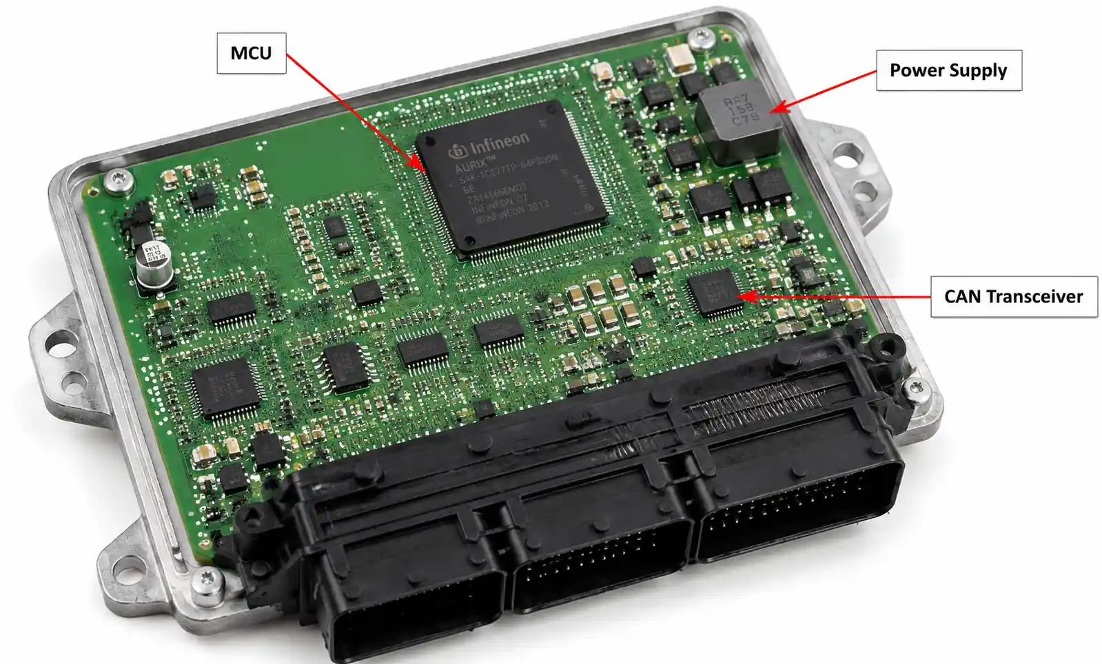
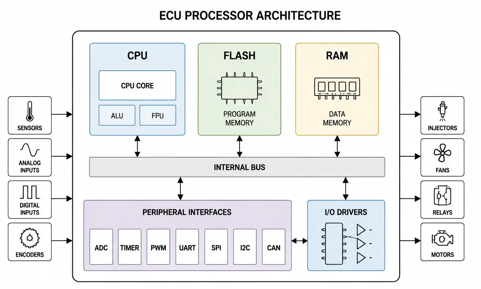
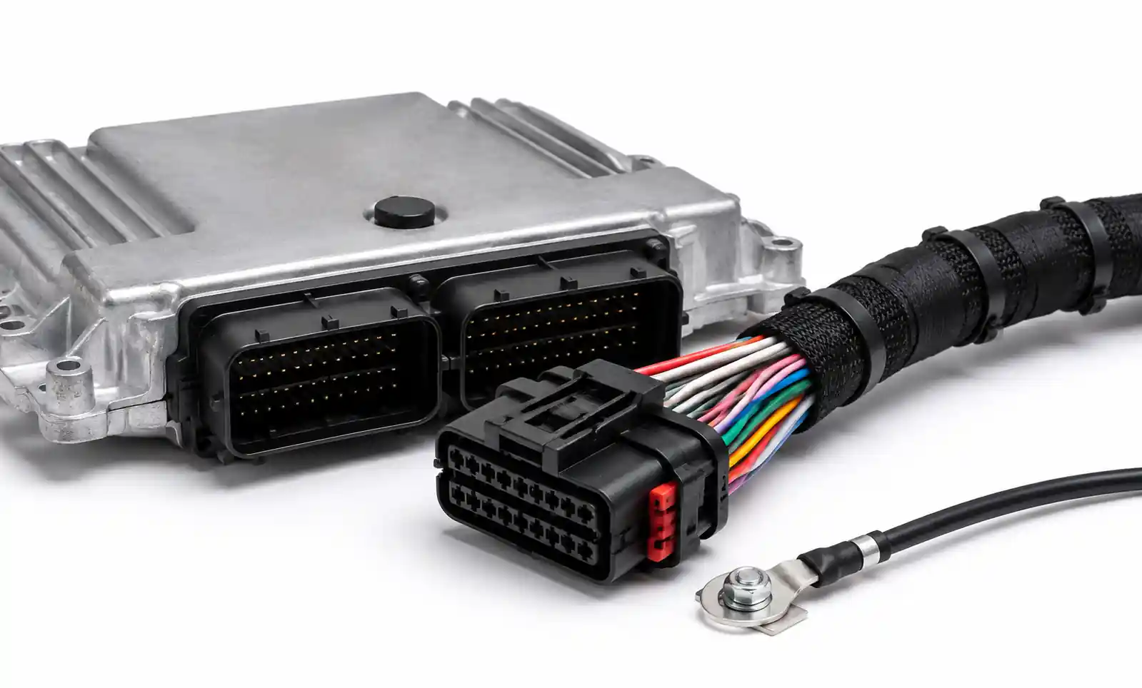
An Engine Control Unit (ECU) is the embedded system that manages engine performance by controlling fuel injection, ignition timing, emissions, and other critical functions. It processes inputs from dozens of sensors and executes thousands of calculations per second to maintain optimal operation across varying conditions.
Why selection matters:
| Consequence of Wrong Selection | Impact |
|---|---|
| Underpowered processor | Inability to run advanced algorithms; poor transient response |
| Insufficient memory | Cannot accommodate OTA updates or calibration changes |
| Inadequate thermal design | Field failures, recalls, warranty costs |
| Missing EMC protection | Erratic behavior, sensor noise, certification failure |
| Wrong I/O configuration | Incompatibility with sensors/actuators; costly respin |
Real-world data: Based on analysis of 27 powertrain programs across OEMs and Tier 1 suppliers, ECU selection mistakes discovered after the hardware freeze stage add 6–12 months to project timelines and $500K–$2M in re-engineering costs.
The ECU market has evolved significantly with electrification and autonomous driving. Traditional engine-only ECUs are being replaced by powertrain control modules (PCMs) that manage hybrid powertrains, electric motors, and ADAS integration. This evolution means designers must now consider scalability, software architecture, and cybersecurity alongside traditional performance metrics.
2. Key Technical Parameters for ECU Selection
2.1 Processing Architecture and Computational Power
Modern automotive ECUs use 32-bit microcontrollers (Infineon AURIX, NXP S32, Renesas RH850, STMicroelectronics Stellar) with clock speeds ranging from 80 MHz to 400 MHz.
| Application | Recommended Clock Speed | Core Architecture | Key Drivers |
|---|---|---|---|
| Port injection (2–4 cyl) | 80–120 MHz | Single-core | Basic fuel/ignition, OBD-II |
| Direct injection (4–6 cyl) | 150–200 MHz | Single/dual-core | Cylinder-individual lambda, VVT |
| Turbocharged gasoline | 180–250 MHz | Dual-core | Boost control, knock detection |
| Diesel common rail | 200–300 MHz | Dual/tri-core | Multi-stage injection, EGR, DPF |
| Hybrid powertrain | 250–400 MHz | Tri/quad-core | Engine-motor coordination, ASIL-D |
| Heavy-duty diesel (6–8+ cyl) | 250–350 MHz | Dual/tri-core | SCR, J1939, advanced emissions |
Engineering insight: Processor speed alone doesn't tell the full story. Core count, cache architecture, and instruction set efficiency matter equally. A 200 MHz dual-core device often outperforms a 300 MHz single-core in real-time control applications.
2.2 Memory Capacity – Real-World Sizing Guide
| Memory Type | Typical Range | Sizing Rule of Thumb |
|---|---|---|
| Flash (program) | 2–16 MB | Code size + 30% margin for OTA/updates |
| RAM (data) | 256 KB – 2 MB | Stack + heap + calibration RAM + 30% margin |
| EEPROM/emulated EEPROM | 64–512 KB | Adaptation values, VIN, fault codes |
Reference sizing by application:
| Application | Flash (MB) | RAM (KB) | Calibration Data (KB) |
|---|---|---|---|
| Port injection (4-cyl) | 2–3 | 256–384 | 500–800 |
| Direct injection (4-cyl) | 4–6 | 512–768 | 800–1,200 |
| Turbo DI (4-cyl) | 6–8 | 768–1,024 | 1,200–1,800 |
| Diesel (6-cyl) | 8–12 | 1,024–2,048 | 1,800–2,500 |
| Hybrid | 12–16 | 2,048+ | 2,500+ |
Critical rule: Leave at least 30% flash margin and 25% RAM margin for post-launch software updates and calibration changes. Undersizing memory is the second most common ECU selection error after inadequate thermal management.
2.3 Input/Output Configuration
ECUs must interface with diverse sensors and actuators. Verify the following:
| I/O Type | Typical Count | Key Specifications |
|---|---|---|
| Analog inputs | 8–24 | 0–5V or 0–12V range, 10–12 bit resolution |
| Digital inputs (crank/cam) | 2–6 | 5V/12V threshold, 0.1° timing resolution |
| High-side drivers (injectors, coils) | 4–12 | Peak current 4–6A, hold current 1–2A |
| Low-side drivers (auxiliary) | 8–16 | Up to 2–3A continuous |
| Sensor supplies (5V/12V) | 2–4 | 50–200 mA each, short-circuit protected |
| CAN/LIN/FlexRay | 2–6 CAN, 1–4 LIN | 500 kbps/1 Mbps CAN FD, ISO 11898 |
| Knock sensor inputs | 1–3 | Differential, 5–150 kHz range |
Critical check: Injector driver peak current capability must exceed your injector requirements by at least 20% margin. Operating drivers at maximum rating reduces reliability and creates thermal stress.
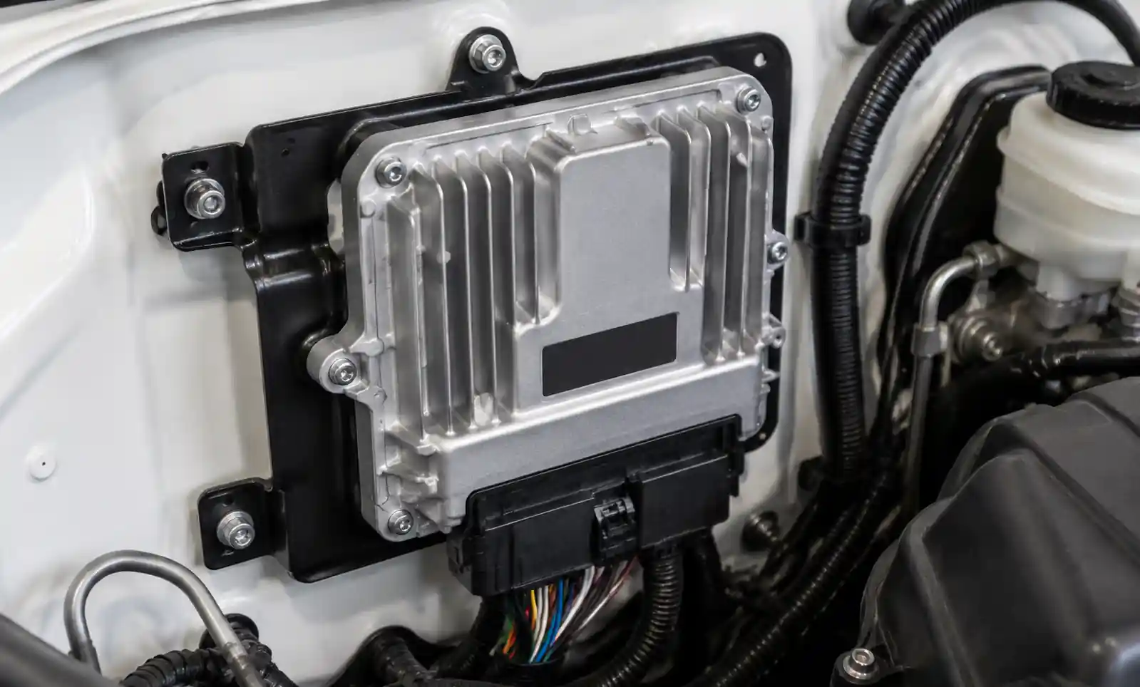
2.4 Operating Temperature and AEC-Q100 Qualification
| Grade | Temperature Range | Typical Application |
|---|---|---|
| Grade 3 | -40°C to +85°C | Cabin-mounted ECUs |
| Grade 2 | -40°C to +105°C | Under-hood (protected) |
| Grade 1 | -40°C to +125°C | Standard under-hood |
| Grade 0 | -40°C to +150°C | Extreme under-hood, diesel, near-engine |
Important: AEC-Q100 Grade 1 is the minimum for most under-hood applications. Grade 0 is recommended for diesel engines and turbocharged gasoline where under-hood temperatures exceed 120°C.
2.5 EMC Performance and Protection
Automotive ECUs must meet these standards:
| Standard | Requirement | Typical Test Level |
|---|---|---|
| ISO 7637-2 | Electrical transients | ±100V load dump, ±300V inductive switching |
| ISO 11452 | Radiated immunity | 100 V/m (field strength) |
| ISO 10605 | ESD | ±8 kV contact, ±15 kV air |
| CISPR 25 | Radiated emissions | Class 3–5 depending on vehicle OEM |
Non-negotiable protections:
- Reverse polarity protection (≥ -14V continuous)
- Overvoltage protection (≥ 24V for 60 min)
- Load dump protection (≥ 100V for 40 ms)
3. How to Choose the Right ECU – A 6-Step Process
Step 1: Define Functional Requirements
Document your engine configuration:
- Number of cylinders and firing order
- Injection system: port, direct, or common rail
- Ignition system: coil-on-plug, distributor, or wasted spark
- Emissions strategy: OBD-II, EOBD, or China 6
- Special features: VVT, turbo, flex-fuel, EGR, SCR
Checklist: [ ] Number of injectors/coils [ ] Sensor types and ranges [ ] Communication interfaces [ ] Power requirements
Step 2: Calculate Processing and Memory Requirements
| Function | Execution Frequency | Approx. Load (%) |
|---|---|---|
| Crank-synchronous (injection/ignition) | 6–12× engine speed | 30–45% |
| Lambda control | 10–50 Hz | 10–15% |
| Idle control | 50–100 Hz | 5–10% |
| Diagnostic monitors | 1–10 Hz | 15–20% |
| CAN/communications | Continuous | 5–10% |
| Total | 65–100% |
Rule: Sum worst-case loads and add 50% margin for future features and peak conditions.
Step 3: Assess Environmental and Reliability Requirements
- Mounting location → determines temperature grade
- Vibration exposure → selects shock/vibration rating
- Expected lifetime → MTBF target (typically 10–15 years / 150,000–300,000 km)
- Harsh environments (marine, off-highway) → conformal coating or sealed enclosure
Step 4: Evaluate Certification and Compliance Needs
| Market | Requirement |
|---|---|
| North America | OBD-II (EPA), CARB approval |
| Europe | EOBD, EC Type Approval |
| China | China 6, CCC certification |
| Global | UN ECE R155 (cybersecurity), ISO 26262 (functional safety) |
Step 5: Consider Software Compatibility and Development Tools
- AUTOSAR compliance? (essential for OEMs, optional for aftermarket)
- Development tools: calibration software, diagnostic interfaces, HIL simulation support
- Supplier technical support: availability, responsiveness, local presence
Step 6: Analyze Total Cost of Ownership
| Cost Component | Low Volume (<1,000/yr) | High Volume (>50,000/yr) |
|---|---|---|
| Unit price | Less dominant | Dominant |
| Development tools | Significant | Amortizable |
| Licensing fees | Significant | Amortizable |
| Calibration effort | Dominant | Significant |
| Certification costs | Fixed, per program | Amortizable |
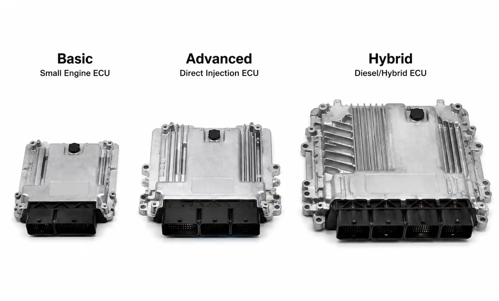
4. ECU Performance Comparison by Application Type
4.1 Application Selection Matrix
| Application Type | Processor Speed | Flash/RAM | Key Features | Cost Range | Cert Level |
|---|---|---|---|---|---|
| Small gasoline (2–4 cyl, port) | 80–120 MHz | 2 MB / 256 KB | Basic fuel/ignition, OBD-II | $50–100 | Grade 1 |
| GDI (4–6 cyl) | 150–200 MHz | 4–6 MB / 512 KB | High-pressure injection, VVT | $120–200 | Grade 1 |
| Turbo gasoline (4–6 cyl) | 180–250 MHz | 6–8 MB / 1 MB | Boost control, knock detection | $180–280 | Grade 0/1 |
| Diesel common rail (4–6 cyl) | 200–300 MHz | 8–12 MB / 1–2 MB | Multi-stage injection, DPF | $250–400 | Grade 0 |
| Hybrid coordinator | 250–400 MHz | 12–16 MB / 2 MB | Engine-motor coordination, ASIL-C/D | $350–600 | Grade 0, ASIL-D |
| Heavy-duty diesel (6–8+ cyl) | 250–350 MHz | 10–16 MB / 2 MB | SCR, J1939 CAN | $300–500 | Grade 0 |
4.2 Decision Tree for ECU Selection
Start: What is your engine configuration? │ ├─ Port injection (2–4 cyl) ──────→ 80–120 MHz, 2–3 MB Flash, Grade 1 │ ├─ GDI (4–6 cyl) ─────────────────→ 150–200 MHz, 4–6 MB Flash, Grade 1 │ ├─ Turbo GDI ─────────────────────→ 180–250 MHz, 6–8 MB Flash, Grade 0/1 │ ├─ Diesel CR (4–6 cyl) ───────────→ 200–300 MHz, 8–12 MB Flash, Grade 0 │ ├─ Heavy-duty diesel (6–8+ cyl) ──→ 250–350 MHz, 10–16 MB Flash, Grade 0 │ └─ Hybrid ────────────────────────→ 250–400 MHz, 12–16 MB Flash, Grade 0, ASIL-D
5. Design Considerations and Common Pitfalls
5.1 Thermal Management – The #1 Design Error
ECU power dissipation: 10–40 watts depending on configuration and load.
| Parameter | Passenger Car | Commercial Vehicle |
|---|---|---|
| Under-hood ambient | up to 105°C | up to 120°C |
| ECU junction temperature | up to 150°C | up to 170°C |
| Required cooling | Natural convection or forced air | Heat sink or liquid cooling |
Thermal design checklist:
- [ ] Calculate worst-case junction temperature using θJC + θCA
- [ ] Verify thermal margin (≥15°C below Tj_max)
- [ ] For high-power applications (>25W), consider liquid cooling
- [ ] Validate under maximum ambient + minimum airflow conditions
5.2 Sensor Signal Conditioning
Common mismatch: NTC thermistor sensors require specific pull-up resistor values.
| Sensor Type | ECU Input Requirement | Typical Pull-Up |
|---|---|---|
| NTC temperature | 5V excitation, 1–10 kΩ pull-up | 2.49 kΩ ±1% |
| Throttle position (potentiometer) | 5V reference, 0–5V input | — |
| Crank/cam (Hall/Variable Reluctance) | Differential input, 2–150 kHz | — |
| Oxygen sensor (wideband) | Bi-directional, current pump | Requires dedicated IC |
Rule: Verify that sensor output voltage ranges match ECU input specifications with margin. A 0–4.5V sensor on a 0–5V input is fine; a 0–12V sensor on a 0–5V input will damage the ADC.
5.3 Power Supply and Grounding Strategy
Automotive electrical environment:
| Condition | Voltage Range | Duration |
|---|---|---|
| Normal operation | 10.5–16V | Continuous |
| Cold crank | 6–9V | 10–30 seconds |
| Jump start | Up to 24V | 5–10 minutes |
| Load dump | Up to 100V | 40–400 ms |
| Transients | ±300V | 50 µs–1 ms |
Grounding: Use star-point ground configuration to prevent high-current loads from creating voltage drops in sensor ground paths. This is critical for oxygen sensors and pressure transducers where millivolt-level accuracy matters.
5.4 Injector and Ignition Coil Driver Capability
| Parameter | Injector Driver | Ignition Coil Driver |
|---|---|---|
| Peak current | 4–6 A (opening) | N/A (dwell current limited by coil) |
| Hold current | 1–2 A | N/A |
| Peak voltage | 40–60 V (flyback) | 300–400 V (kickback) |
| Typical driver type | Peak-and-hold | IGBT or MOSFET |
Critical rule: Verify driver specifications include at least 20% margin above your actuator requirements. Operating drivers at maximum rating reduces reliability and creates thermal stress.
5.5 Software Calibration Complexity – A Worked Example
Example: 4-cylinder GDI engine, 6-speed transmission.
| Calibration Task | Approx. Hours | Dyno Time |
|---|---|---|
| Fuel maps (WOT, part-load) | 80 | 40 hours |
| Ignition timing maps | 60 | 30 hours |
| VVT schedules | 40 | 20 hours |
| Transient compensation | 80 | 40 hours |
| Idle quality | 40 | 20 hours |
| OBD-II monitors | 100 | 50 hours |
| Cold start and warm-up | 60 | 30 hours |
| Total | 460 hours | 230 hours |
At $500/hour dyno time + $150/hour engineer rate: Total calibration cost ≈ $184,000–$230,000.
Select an ECU with comprehensive calibration tools—preferably one already used by your calibration service provider—to avoid tool compatibility issues.
5.6 Diagnostic Coverage and OBD-II Compliance
OBD-II/EOBD mandates extensive diagnostic monitors:
| Monitor | Approx. Code Size | Approx. CPU Load |
|---|---|---|
| Misfire detection | 20–40 KB | 15–20% |
| Catalyst efficiency | 10–20 KB | 5–10% |
| Oxygen sensor response | 10–20 KB | 5–8% |
| EGR function | 10–15 KB | 3–5% |
| Evaporative system | 10–20 KB | 3–5% |
| Total | 60–115 KB | 31–48% |
Critical: Inadequate diagnostic capability discovered during certification testing can delay production by 3–6 months.
5.7 Case Study: Thermal Failure in a 300 HP Diesel ECU
Background: A heavy-duty diesel OEM selected a Grade 1 (-40°C to +125°C) ECU for a 300 HP off-highway application. The ECU was mounted on the engine block near the turbocharger.
Problem: After 6 months of field operation, 8% of ECUs failed with blown power MOSFETs and solder fatigue on the main processor.
Root Cause Analysis:
- Actual under-hood ambient temperature: 135°C (vs. 125°C design assumption)
- ECU power dissipation: 28 watts continuous
- Junction temperature: 165°C (exceeding 150°C maximum)
Solution:
- Upgraded to Grade 0 (-40°C to +150°C) ECU with 250°C solder
- Added forced-air cooling duct to ECU mounting location
- Reduced injection driver current from 5.5A to 4.8A (still within injector requirements)
Result: Field failure rate dropped from 8% to 0.2%. Total cost of recall and redesign: $4.2M.
Lesson: Always verify thermal performance under actual worst-case conditions—don't rely on datasheet assumptions.
6. Supply Chain and Sourcing Considerations
6.1 Lead Time and Availability
| ECU Type | Initial Lead Time | Repeat Order Lead Time |
|---|---|---|
| Standard catalog ECU | 12–26 weeks | 4–8 weeks |
| Custom ECU (new design) | 6–12 months | 8–16 weeks |
| Automotive-grade (AEC-Q100) | +4–8 weeks vs. commercial | +2–4 weeks |
Planning rule: Order 2–3 months of buffer inventory for critical projects, especially during low-volume production phases.
6.2 Multi-Source Strategy and Counterfeit Risk
Multi-sourcing benefits:
- Negotiating leverage (10–20% price reduction)
- Protection against supply disruptions
- Competitive pressure on quality and support
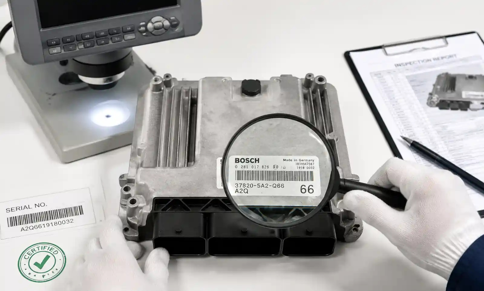
Counterfeit prevention:
- Purchase ONLY from authorized distributors or direct from manufacturers
- Incoming inspection: visual inspection, electrical testing, thermal cycling
- Verify lot traceability and date codes
- Test critical parameters (current capability, timing accuracy)
6.3 Obsolescence Management
| Vehicle Lifecycle | Semiconductor Lifecycle | Risk |
|---|---|---|
| 10–15 years | 5–7 years | High |
Mitigation strategies:
- Select suppliers with long-term availability commitments
- Choose ECU platforms with multiple processor options
- Request last-time-buy (LTB) notification (typically 12–18 months' notice)
- Consider lifetime buy for very low-volume applications
6.4 Regional Compliance and Documentation
| Market | Required Certification |
|---|---|
| North America | EPA certification, CARB approval |
| Europe | EC Type Approval, emissions conformity |
| China | CCC certification, China 6 |
| Global | UN ECE R155 (cybersecurity), ISO 26262 |
Warning: Missing or incomplete certification documents can delay market entry by 3–6 months or prevent sales entirely.
6.5 Total Cost of Ownership – A Worked Example
Scenario: 4-cylinder GDI ECU, 50,000 units/year, 5-year program (250,000 units total).
| Cost Component | Option A (Low-Cost ECU) | Option B (Premium ECU) |
|---|---|---|
| Unit price | $85 | $120 |
| Total hardware cost | $21.25M | $30.00M |
| Development tools | $50K | $80K |
| Calibration effort (600 hours) | $300K | $300K |
| Certification (OBD-II + CARB) | $150K | $150K |
| Supplier support (FAE hours) | 200 hrs × $250 = $50K | 600 hrs × $250 = $150K |
| 5-year TCO | $21.80M | $30.68M |
| Per-unit TCO | $87.20 | $122.72 |
But wait—Option B includes:
- 30% faster processor → enables future OTA updates without hardware change
- Additional 2 MB flash → accommodates upcoming Euro 7 calibration changes
- Grade 0 qualification → can be reused on next-gen engine (no redesign)
True 10-year TCO (two programs):
- Option A: $21.80M + next-gen redesign ($4M) = $25.80M
- Option B: $30.68M + minor software port = $30.90M
Conclusion: Option A is cheaper in the short term, but if your product roadmap extends beyond 5 years, the premium ECU may be more cost-effective.
7. FAQ
What is the difference between an ECU and a PCM?
An ECU controls engine functions only. A PCM (Powertrain Control Module) integrates engine and transmission control. For transmission-integrated systems, select a PCM; otherwise, a standalone ECU is more cost-effective.
How do I calculate required processing power?
Sum the computational load of all control loops at maximum engine speed and add 50% margin. Rough guide: 4-cyl port injection → 80–120 MHz; GDI → 150–200 MHz; diesel/hybrid → 200–400 MHz.
Can I use an industrial ECU for automotive applications?
For off-road applications, possibly. For on-road vehicles: No. Industrial ECUs lack AEC-Q100 qualification, OBD-II compliance, and may not survive automotive electrical transients.
What are the key ECU datasheet parameters?
Processor speed and core count, flash/RAM capacity, I/O types and counts, temperature grade, EMC standards, injector driver current ratings, sensor supply outputs, and communication interfaces.
How far ahead should I order ECUs?
Standard ECUs: 6–9 months before on-vehicle date. Custom ECUs: 12–18 months. Buffer inventory: 2–3 months of consumption.
What validation testing is required?
Bench testing (sensors/actuators), thermal testing (-40°C to +125°C), EMC testing (ISO standards), engine dyno testing (200–500 hours), and vehicle durability testing (10,000–50,000 km).
Is AUTOSAR essential?
For OEMs and high-volume production, yes—it enables supplier flexibility and software reuse. For aftermarket or low-volume, proprietary software may be faster and cheaper to develop.
8. Conclusion
Key Takeaways:
- Match specifications to application—don't over-specify (wastes cost) or under-specify (creates performance bottlenecks).
- Leave 30% margin on flash and RAM—software always grows.
- Thermal management is #1—verify junction temperature under worst-case conditions.
- AEC-Q100 Grade 1 or 0 is non-negotiable for on-road vehicles.
- TCO analysis must include tools, calibration, certification, and supply chain risk—not just unit price.
- Plan procurement 6–12 months ahead—automotive ECUs have longer lead times.
Immediate Actions:
- [ ] Document your engine configuration and functional requirements
- [ ] Calculate processor and memory requirements using the tables in Sections 2.1–2.2
- [ ] Review thermal design under worst-case ambient conditions
- [ ] Identify certification requirements for your target markets
- [ ] Request ECU datasheets from 2–3 suppliers and compare I/O compatibility
- [ ] Perform TCO analysis using the template in Section 6.5