


Gyroscope Sensor Selection Guide: How to Choose the Right MEMS Gyroscope for Your Application
Selecting the right gyroscope sensor requires understanding the trade-offs between measurement range, sensitivity, noise performance, and power consumption. This guide walks you through the key technical parameters, application-specific selection criteria, and design considerations that directly impact system performance in motion sensing applications.
Table of Contents
- Introduction: What This Guide Covers
- Key Technical Parameters Explained
- How to Choose the Right Gyroscope Sensor
- Performance Comparison by Application
- Design Considerations and Common Pitfalls
- Supply Chain and Sourcing Considerations
- FAQ
- Conclusion
1. Introduction: What This Guide Covers
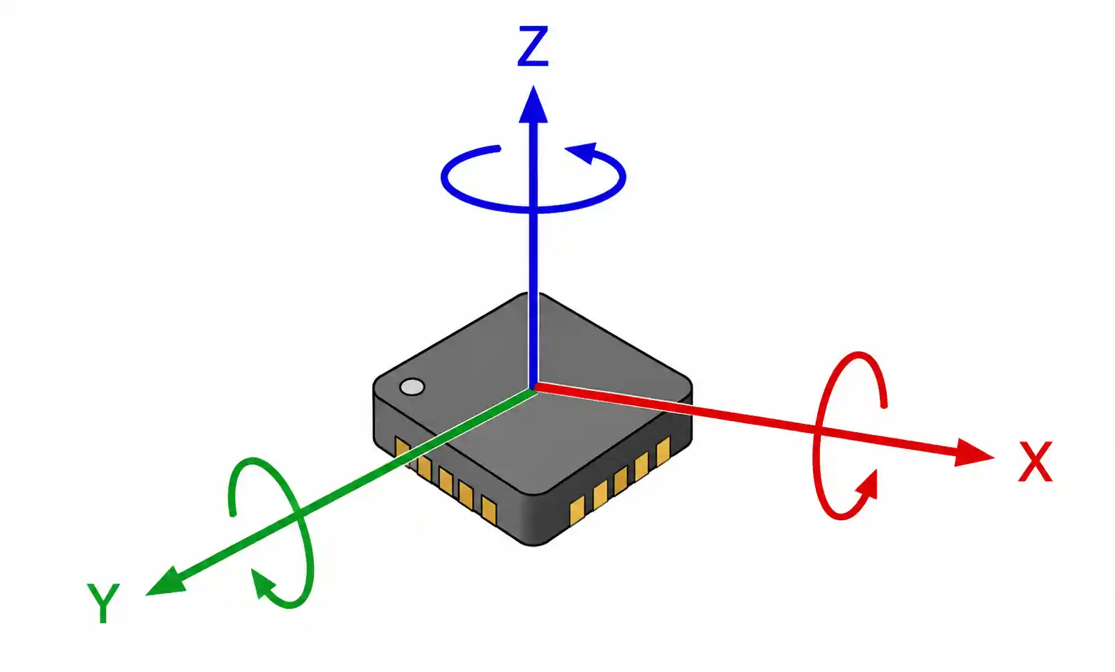
Gyroscope sensors measure angular velocity and are essential components in modern motion-tracking systems. From smartphone screen rotation to automotive stability control and drone flight stabilization, MEMS gyroscopes have become the standard solution due to their compact size, low power consumption, and cost-effectiveness compared to traditional mechanical gyroscopes.
This guide is written for design engineers, R&D teams, and procurement managers who need to select gyroscope sensors for specific applications. Rather than providing a general overview of gyroscope technology, we focus on the selection methodology, parameter trade-offs, and practical design considerations based on real-world engineering requirements.
Whether you are designing an IMU for industrial robotics, adding motion sensing to a wearable device, or implementing stabilization in a camera gimbal, understanding how gyroscope specifications translate to system performance is critical. We cover the parameters that matter most for your application, common selection mistakes, and how to validate your choice through proper testing and design verification.
2. Key Technical Parameters Explained
Understanding gyroscope specifications requires going beyond datasheet values to grasp how each parameter affects your system's performance. Here are the critical parameters that drive selection decisions.
Measurement Range and Full-Scale Range
The measurement range, typically specified in degrees per second (°/s or dps), defines the maximum angular velocity the sensor can measure. Common ranges include ±250, ±500, ±1000, and ±2000 dps. The key is matching the range to your application's expected rotational speeds. A smartphone screen rotation application rarely exceeds 500 dps, while a drone performing aggressive maneuvers may require 2000 dps or higher.
Selecting a range that is too wide for your application reduces effective resolution. Since the ADC bit depth remains constant, spreading it across a wider range means each LSB represents a larger angular velocity increment. For precision applications, use the narrowest range that accommodates your maximum expected angular rate plus a reasonable margin.
Sensitivity and Resolution
Sensitivity is expressed in LSB/dps (least significant bits per degree per second) or mV/dps for analog outputs. Higher sensitivity provides better resolution for detecting small angular movements. However, sensitivity alone does not determine system accuracy—you must also consider noise density and bias stability.
Resolution depends on both the ADC bit depth and the selected measurement range. A 16-bit gyroscope with a ±250 dps range offers approximately 0.0076 dps per LSB, while the same sensor configured for ±2000 dps provides only 0.061 dps per LSB. This eight-fold difference in resolution can be critical for applications requiring precise angular position tracking through integration.
Noise Density and Allan Deviation
Noise density, measured in °/s/√Hz or mdps/√Hz, characterizes the sensor's noise floor across the frequency spectrum. Lower noise density enables detection of smaller angular velocities and improves angle accuracy when integrating gyroscope output over time. For high-precision applications like surveying equipment or antenna pointing systems, noise density below 0.01 °/s/√Hz is typically required.
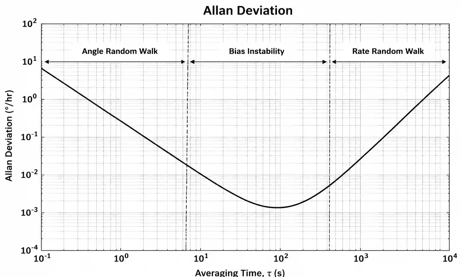
Allan deviation plots provide a comprehensive view of gyroscope noise characteristics across different integration times. The plot reveals angle random walk (short-term noise), bias instability (flicker noise at medium timescales), and rate random walk (long-term drift). Understanding these characteristics is essential for applications involving dead reckoning or long-duration attitude estimation.
Zero-Rate Output and Bias Stability
Zero-rate output (ZRO), also called offset or bias, is the sensor output when no rotation is present. Initial offset at power-on can be calibrated out, but bias instability—how much the offset drifts over time and temperature—directly affects system accuracy. Bias instability is typically specified in °/h (degrees per hour) and represents the minimum achievable drift rate after calibration.
For navigation applications, bias stability is often the limiting factor in position accuracy. A gyroscope with 10 °/h bias instability will accumulate approximately 240 degrees of error over 24 hours if not corrected. Consumer-grade MEMS gyroscopes typically exhibit 5-50 °/h bias instability, while tactical-grade devices achieve 0.1-10 °/h, and navigation-grade sensors reach below 0.01 °/h.
Bandwidth and Output Data Rate
Bandwidth defines the frequency range of angular rate inputs the sensor can accurately measure. For most motion sensing applications, a bandwidth of 50-100 Hz is sufficient to capture human motion or slow robotic movements. High-speed applications like vibration analysis or impact detection require wider bandwidth, often 200 Hz or higher.
Output data rate (ODR) must be at least twice the signal bandwidth according to the Nyquist criterion, but practical systems typically use 4-10x oversampling for effective digital filtering and noise reduction. Common ODRs range from 100 Hz for low-power applications to 8 kHz for high-performance systems. Note that higher ODR increases power consumption and data processing requirements.
3. How to Choose the Right Gyroscope Sensor
Selecting a gyroscope requires mapping application requirements to sensor specifications through a systematic evaluation process. Here is a practical methodology based on design experience across multiple domains.
Step 1: Define Application Requirements
Start by quantifying your system's requirements in engineering terms. What is the maximum angular velocity you need to measure? What angular position accuracy must you maintain, and over what time period? What environmental conditions (temperature range, shock, vibration) must the sensor withstand? What power budget is available?
For example, a smartphone application might require: ±500 dps range, 1° accuracy for screen rotation, -20°C to 60°C operation, less than 1 mA average current consumption. An industrial robot joint sensor might need: ±250 dps range, 0.1° position accuracy over continuous operation, -40°C to 85°C, shock tolerance to 10,000g, and redundant failure detection.
Step 2: Select Measurement Range
Choose the narrowest measurement range that accommodates your maximum expected angular rate with a safety margin of 20-30%. If your application involves 300 dps maximum rotation, select a ±500 dps sensor rather than ±2000 dps. This preserves resolution and signal-to-noise ratio.
For applications with widely varying angular velocities, consider sensors with programmable ranges. Many modern MEMS gyroscopes allow software-configurable range selection, enabling you to optimize resolution dynamically based on operating conditions.
Step 3: Evaluate Noise Performance
Calculate the angle error budget from noise integration. If your application integrates gyroscope output to estimate angle, noise density and bias stability become critical. Use the Allan deviation specification to estimate drift over your required operation time.
A quick approximation: angle random walk (in °/√hr) multiplied by the square root of measurement time (in hours) gives the expected angle drift from noise. For 10-minute operation with 0.1 °/√hr angle random walk, expect approximately 0.04° of drift from this noise source alone.
Step 4: Assess Temperature Stability
Temperature sensitivity affects both offset and scale factor. Review the temperature coefficient specifications: bias vs. temperature (°/s/°C) and sensitivity change over temperature (ppm/°C or %/°C). For outdoor applications or systems with significant self-heating, temperature compensation becomes essential.
Some gyroscopes include internal temperature sensors and provide factory-calibrated compensation coefficients in device registers. Implementing this compensation in your firmware can reduce temperature-induced errors by 5-10x compared to uncompensated operation.
4. Performance Comparison by Application
Different applications prioritize different gyroscope characteristics. This comparison helps you identify which specifications matter most for your use case.
| Application | Measurement Range | Key Performance Metric | Typical Bias Stability | Power Budget | Example Parts |
|---|---|---|---|---|---|
| Smartphone / Tablet | ±500 to ±2000 dps | Power consumption | 5-20 °/h | <1 mA | BMI270, ICM-42605 |
| Drone / UAV | ±2000 to ±4000 dps | Update rate, shock tolerance | 10-30 °/h | 2-5 mA | MPU-6500, BMI088 |
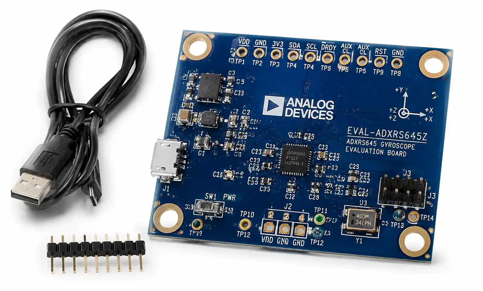
| Industrial Robot | ±250 to ±1000 dps | Bias stability, linearity | 2-10 °/h | Not critical | ADXRS645, L3GD20H |
| Automotive (ADAS/ESC) | ±300 to ±500 dps | Temperature stability, AEC-Q100 | 1-5 °/h | <3 mA | BMI260, LSM6DSO32 |
| Camera Stabilization | ±125 to ±500 dps | Noise density, bandwidth | 5-15 °/h | <2 mA | LSM6DS3TR-C, BMG250 |
| Wearable Fitness | ±500 to ±1000 dps | Ultra-low power | 10-30 °/h | <0.5 mA | BMA456, KX126-1063 |
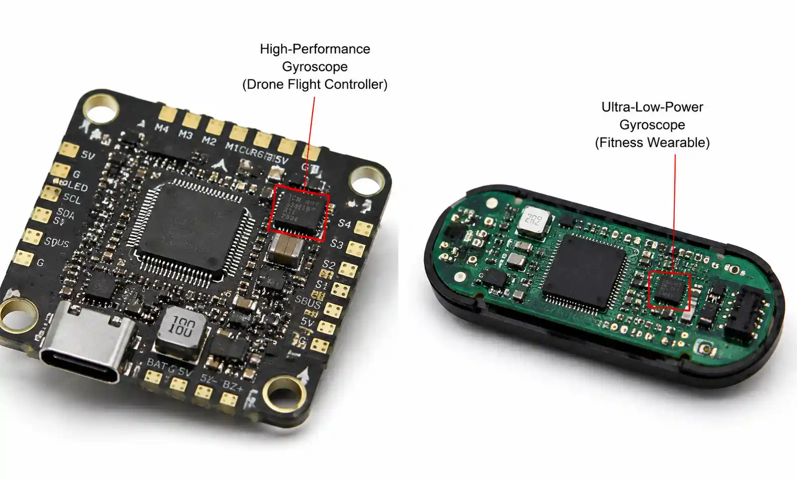
This table highlights the parameter trade-offs across applications. High-speed motion (drones) demands wide measurement range and fast update rates but can tolerate higher noise and power consumption. Precision applications (robotics, surveying) require excellent bias stability and low noise but operate at moderate angular rates. Battery-powered devices (wearables) prioritize power consumption above absolute accuracy.
When evaluating gyroscopes for your application, identify your non-negotiable requirements first. If you must meet AEC-Q100 qualification for automotive use, that immediately narrows your options. If you have a 200 µA power budget for always-on motion detection, that constraint drives sensor selection more than any performance parameter.
| Selection Priority | Primary Applications | Secondary Consideration |
|---|---|---|
| Noise density < 0.01 °/s/√Hz | Navigation, surveying, precision robotics | Bias stability, temperature performance |
| Bias stability < 5 °/h | Dead reckoning, long-duration attitude tracking | Noise density, shock tolerance |
| Power < 500 µA | Wearables, IoT sensors, battery-powered devices | Measurement range, data rate flexibility |
| Shock tolerance > 5000g | Industrial equipment, automotive, handheld tools | Package type, mounting recommendations |
| Operating temp -40 to 125°C | Automotive, industrial, outdoor equipment | Temperature compensation features |
5. Design Considerations and Common Pitfalls
Proper gyroscope integration requires attention to PCB layout, power supply design, calibration procedures, and mechanical mounting. These implementation details often determine whether you achieve datasheet performance in your system.
PCB Layout and Mechanical Mounting
Mount the gyroscope as close as possible to the system's center of rotation. Off-center mounting introduces translational acceleration components that couple into gyroscope readings, especially during combined linear and rotational motion. For a gyroscope mounted 5 cm from the rotation center, a 1g linear acceleration produces an apparent angular velocity error of approximately 2 rad/s (115 dps)—significant for many applications.
Secure mechanical mounting is critical. Any flexibility or play in the mounting allows the sensor to experience local vibrations different from the intended measurement target. Use four-point mounting for larger packages and ensure the PCB itself is rigidly supported. For high-vibration environments, consider vibration isolation mounts, but recognize this may introduce phase lag in dynamic response.
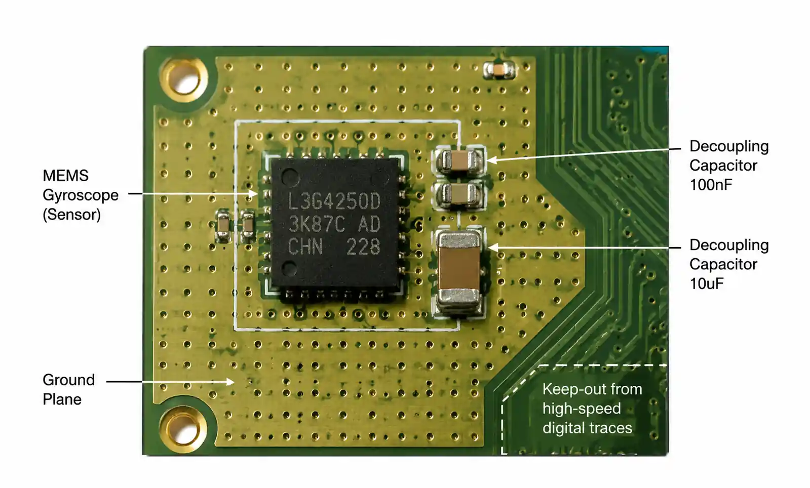
Pay attention to PCB routing near the gyroscope. Keep high-speed digital signals and switching power supplies away from the sensor to minimize electromagnetic interference. Use a solid ground plane beneath the gyroscope and place decoupling capacitors as close as possible to the power pins. Typical recommendations include a 100 nF ceramic capacitor within 2-3 mm of the VDD pin, plus a 10 µF bulk capacitor nearby.
Power Supply Requirements
MEMS gyroscopes are sensitive to power supply noise, which couples directly into the analog sensing circuits. Maintain power supply ripple below 50 mV peak-to-peak, preferably below 10 mV for high-precision applications. Use a low-noise LDO regulator dedicated to the gyroscope rather than sharing a switching regulator output with digital circuits.
The power-up sequence matters for some devices. Review the datasheet for any requirements regarding voltage ramp rate, settling time before first communication, or initialization procedures. Many gyroscopes require 10-100 ms after power-on before valid data is available, as internal circuits stabilize and self-test routines complete.
Calibration and Compensation
Factory calibration provides baseline accuracy, but application-specific calibration significantly improves performance. At minimum, implement a zero-rate calibration routine that measures offset when the system is stationary and subtracts this value from subsequent readings. For best results, perform this calibration after the device reaches thermal equilibrium.
Temperature compensation reduces drift across the operating temperature range. The simplest approach captures offset values at several temperature points during production and stores a compensation lookup table or polynomial coefficients in non-volatile memory. More sophisticated methods also compensate scale factor and axis misalignment changes with temperature.
Cross-axis sensitivity—the sensor's response to angular rates about non-primary axes—typically ranges from 1% to 5% in MEMS gyroscopes. For applications requiring tight coupling between axes or accurate 3D angular velocity measurement, characterize and compensate for cross-axis effects through a rotation matrix transformation.
Common Design Mistakes to Avoid
One frequent error is underestimating the impact of vibration on gyroscope readings. High-frequency vibration can alias into the measurement bandwidth, creating apparent angular rates that do not correspond to actual rotation. Implement anti-aliasing filters before the ADC (for analog output gyroscopes) or use the sensor's built-in digital low-pass filter configured appropriately for your application.
Another mistake is neglecting gyroscope warm-up drift. Offset changes significantly during the first few minutes after power-on as the device self-heats from internal power dissipation. For applications requiring immediate accurate readings after power-up, either maintain the gyroscope in a low-power standby mode or characterize the warm-up profile and compensate accordingly.
Failing to validate gyroscope performance under actual operating conditions is perhaps the most serious oversight. Bench testing at room temperature with gentle manual rotation provides limited confidence. Test your design across the full temperature range, subject it to expected shock and vibration profiles, and verify performance over extended operation periods to catch issues with bias drift and environmental sensitivity.
6. Supply Chain and Sourcing Considerations
Gyroscope availability, lead times, and lifecycle management significantly impact product development timelines and manufacturing scalability. Understanding the supply chain landscape helps mitigate risks.
Major Suppliers and Market Position
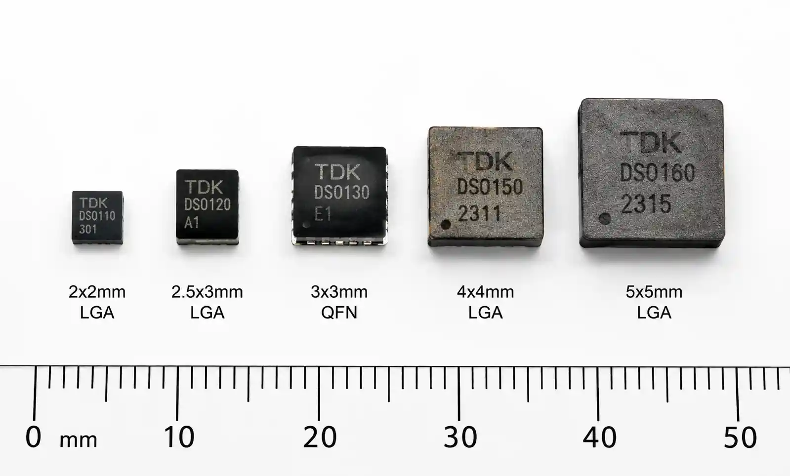
The MEMS gyroscope market is dominated by several key suppliers: Bosch Sensortec, STMicroelectronics, TDK InvenSense (now part of TDK), Analog Devices, and Murata. Each has different strengths—Bosch and ST focus heavily on consumer and automotive markets with high-volume, cost-optimized parts. TDK InvenSense pioneered many consumer MEMS gyroscopes. Analog Devices offers higher-performance options for industrial and precision applications.
For high-volume consumer products, parts from Bosch (BMI series) and ST (LSM series) typically offer the best combination of performance, cost, and availability. For automotive applications requiring AEC-Q100 qualification, ST, Bosch, and TDK all have qualified portfolios. Industrial applications often benefit from Analog Devices' wider temperature ranges and longer lifecycle commitments.
Lead Time and Inventory Management
Standard gyroscope sensors typically have lead times ranging from stock availability to 12-16 weeks, depending on market conditions and demand fluctuations. Automotive-qualified variants often have longer lead times due to additional testing and qualification requirements. Plan for 20-26 week lead times for automotive-grade sensors during tight supply periods.
For prototype and low-volume production, purchasing from distributors like Digi-Key, Mouser, or Arrow provides immediate availability but at higher unit costs. Production volumes above 10,000 units annually often justify direct supplier relationships, which provide better pricing, lead time visibility, and technical support access.
| Supplier | Consumer Focus | Automotive Grade | Industrial Grade | Typical MOQ (Direct) | Lead Time (Stock) |
|---|---|---|---|---|---|
| Bosch Sensortec | High | High | Medium | 3,000-5,000 | Stock - 12 weeks |
| STMicroelectronics | High | High | High | 2,500-5,000 | Stock - 16 weeks |
| TDK InvenSense | High | Medium | Medium | 5,000-10,000 | Stock - 12 weeks |
| Analog Devices | Medium | Medium | High | 1,000-2,500 | Stock - 20 weeks |
| Murata | Medium | High | High | 5,000-10,000 | 12 - 20 weeks |
Obsolescence and Alternative Parts
MEMS gyroscopes have product lifecycles ranging from 5-7 years for consumer-focused parts to 10-15 years for industrial and automotive-qualified devices. Check the manufacturer's product longevity commitments, especially for products expected to remain in production for many years.
Design for pin-compatible alternatives when possible. Many gyroscopes within a supplier's family share pinouts and communication protocols, allowing you to substitute a different performance grade or generation with minimal PCB changes. For critical applications, validate at least one alternative part during the design phase so you have a qualified backup if your primary choice faces supply constraints or end-of-life.
When a gyroscope reaches end-of-life, suppliers typically provide 6-12 months advance notice and offer last-time-buy opportunities. Have a migration plan ready, including firmware changes needed to support the replacement sensor and any recalibration required for your application.
7. FAQ
What is the difference between a gyroscope and an accelerometer?
A gyroscope measures angular velocity (rotation rate) around one or more axes, while an accelerometer measures linear acceleration. Gyroscopes detect how fast something is rotating, whereas accelerometers detect changes in velocity or orientation relative to gravity. Most motion sensing systems combine both sensors in an IMU (Inertial Measurement Unit) to track both linear and rotational motion. Using both sensor types together enables more accurate position and orientation tracking than either sensor alone.
How do I convert gyroscope output to angle?
Gyroscope output is angular velocity, which must be integrated over time to obtain angle. In discrete systems, multiply the angular velocity reading by the time interval between samples and sum these increments. For example, if your gyroscope reads 10 °/s and you sample at 100 Hz, each sample represents 0.1° of rotation. However, integration accumulates all errors including noise and bias drift, causing angle estimates to drift over time. Most practical systems fuse gyroscope data with accelerometer or magnetometer readings to bound this drift.
What does bias stability specification mean for my application?
Bias stability represents how much the zero-rate offset drifts over time, typically specified in °/h. This drift directly limits how long you can integrate gyroscope data before accumulated angle error becomes unacceptable. A gyroscope with 10 °/h bias stability may drift 10 degrees in one hour even when perfectly stationary. For short-duration measurements (seconds to minutes), bias stability has minimal impact. For applications requiring accurate orientation over hours without external reference updates, bias stability becomes the dominant error source and you need tactical-grade or navigation-grade gyroscopes.
Can I use a 3-axis gyroscope in place of three single-axis sensors?
Yes, and this is the standard approach in modern designs. A 3-axis MEMS gyroscope integrates three sensing elements into a single package, measuring angular velocity around X, Y, and Z axes simultaneously. This provides significant advantages: smaller PCB footprint, lower power consumption, reduced component count, and better axis alignment compared to three discrete sensors. The main consideration is that all three axes share common power and communication interfaces, so you cannot independently configure each axis if your application requires different ranges or bandwidths per axis.
How do I handle the initial offset calibration?
Perform zero-rate calibration when the system is stationary, ideally after the gyroscope reaches thermal equilibrium (typically 2-5 minutes after power-on). Collect 50-100 samples at your normal operating data rate, average them to reduce noise, and store this average as the offset correction. Subtract this offset from all subsequent readings. Recalibrate whenever the system starts from a powered-off state or if operating temperature changes significantly. For consumer devices, trigger recalibration when the system detects a stationary period (all sensors show minimal change for several seconds). For industrial applications, implement a formal calibration procedure as part of startup or maintenance routines.
What sampling rate should I use for my gyroscope?
Select a sampling rate at least 4-5x higher than the highest frequency motion you need to measure. For human motion tracking, 100-200 Hz suffices. For high-speed robotics or vibration monitoring, 1-4 kHz may be necessary. Higher sampling rates enable better digital filtering and reduce quantization noise, but increase power consumption and data processing requirements. Many gyroscopes offer configurable output data rates—start with a higher rate during development to capture unexpected high-frequency content, then reduce to the minimum necessary rate for production to optimize power consumption.
Are automotive-grade gyroscopes required for all automotive applications?
For systems safety-critical or directly related to vehicle control (ESC, ADAS, airbag deployment), AEC-Q100 qualified sensors are typically required by automotive manufacturers and are often mandated by functional safety standards like ISO 26262. For non-safety-related applications like infotainment system gesture control or dashcam stabilization, industrial-grade sensors may suffice depending on your customer's requirements. However, even non-critical automotive applications must withstand harsh temperature cycling, long-term reliability, and exposure to automotive electromagnetic environments. Using automotive-qualified parts simplifies qualification and reduces field failure risk, even when not strictly required.
How do I protect the gyroscope from mechanical shock during shipping?
MEMS gyroscopes are generally robust to mechanical shock when unpowered, typically withstanding 10,000g or higher. However, shock during operation (when sensing elements are in motion) poses greater risk. Design your PCB mounting to isolate the sensor from case impacts and drops. Use conformal coating or protective covers if the sensor is exposed. For products shipped with batteries installed (gyroscope potentially powered), ensure adequate packaging cushioning and test your design against IETM packaging standards or equivalent drop test specifications relevant to your product category.
8. Conclusion
Picking a gyroscope is all about trade‑offs: range, noise, bias stability, and power. Consumer stuff? Go cheap and low‑power. Industrial or automotive? You need long‑term stability and wide‑temperature operation. Get the balance right and you won't over‑specify.
For screen rotation, gesture, or activity tracking, consumer MEMS gyros from Bosch or ST in the ±500 to ±2000 dps range usually do the job. For robotics, camera stabilization, or anything needing sub‑degree accuracy over time, look for bias stability under 10 °/h and noise density below 0.015 °/s/√Hz.
Bottom line: start with clear requirements—range, accuracy, temp, power, lifetime. Filter candidates, then test the top picks in real conditions. That systematic approach gets you a gyro that performs, works in production, and stays supportable over your product's life.