


TRIAC Dimmer Selection Guide: Technical Parameters, LED Compatibility, and Design Considerations
When designing lighting control systems or selecting AC power control solutions for modern applications, understanding TRIAC dimmer technology is essential. This guide helps engineers, procurement managers, and design teams navigate the technical parameters, compatibility challenges, and practical design considerations for TRIAC-based dimming circuits.
Table of Contents
- What is a TRIAC Dimmer and How Does It Work
- Key Technical Parameters Explained
- TRIAC Dimmer Types: Leading-Edge vs Trailing-Edge
- LED Compatibility Challenges and Solutions
- Design Considerations and Common Pitfalls
- Application-Specific Selection Criteria
- FAQ
- Conclusion
1. What is a TRIAC Dimmer and How Does It Work
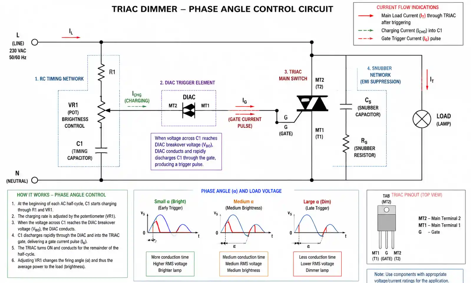
A TRIAC (Triode for Alternating Current) dimmer is a phase-control semiconductor device that regulates AC power delivery by controlling the conduction angle during each half-cycle of the AC waveform. Unlike resistive dimming methods that waste energy as heat, TRIAC dimmers modulate power by rapidly switching the AC waveform on and off.
The basic operating principle involves delaying the point at which the TRIAC conducts during each AC cycle. By varying the trigger point through a control circuit—typically using a DIAC and potentiometer—the dimmer adjusts the effective voltage and current delivered to the load. The later the TRIAC triggers in each half-cycle, the less average power reaches the load, resulting in dimmer illumination or reduced motor speed.
In residential and commercial lighting applications, TRIAC dimmers provide a cost-effective solution for controlling incandescent, halogen, and compatible LED fixtures. The technology's simplicity and compatibility with existing two-wire installations make it the dominant dimming method in North American and European markets.
2. Key Technical Parameters Explained
When evaluating TRIAC dimmers for your application, several technical parameters directly impact performance, reliability, and compatibility.
Voltage Rating: TRIAC dimmers are designed for specific AC line voltages—typically 110-120V AC (North America) or 220-240V AC (Europe/Asia). The voltage rating must exceed the maximum line voltage by at least 20% to ensure reliable operation and account for voltage transients. For 120V applications, select TRIACs rated for at least 400V; for 240V systems, 600V-rated devices are standard.
Current Rating: The dimmer's current rating determines the maximum load it can safely control. Traditional incandescent-focused dimmers were rated for 300W to 1000W loads. However, LED loads require different considerations due to inrush current characteristics. When selecting for LED applications, verify the dimmer specifies LED-compatible current ratings, not just incandescent wattage.
Power Dissipation: TRIACs exhibit a forward voltage drop of approximately 1-1.5V when conducting, generating heat proportional to the load current. Proper thermal management through heatsinking is critical for loads exceeding 200W. Calculate power dissipation using: P = V_F × I_load, where V_F is the forward voltage drop and I_load is the RMS load current.
Trigger Current (I_GT): This parameter defines the minimum gate current required to trigger the TRIAC into conduction. Typical values range from 5mA to 50mA depending on the device sensitivity. Lower trigger currents enable simpler control circuits but may increase susceptibility to noise-induced false triggering.
Holding Current (I_H): Once triggered, the TRIAC requires a minimum holding current to remain in conduction. For LED applications with low average currents, this parameter becomes critical—if the load current falls below I_H, the TRIAC may fail to conduct properly, causing flickering or dropout at low dimming levels.
| Parameter | Typical Range | Impact on Performance |
|---|---|---|
| Voltage Rating (V_DRM) | 400V-800V | Must exceed peak line voltage + transients; undersizing causes device failure |
| Current Rating (I_T(RMS)) | 2A-16A | Determines maximum load capacity; verify derating for LED applications |
| Trigger Current (I_GT) | 5mA-50mA | Lower values simplify control circuits; higher values improve noise immunity |
| Holding Current (I_H) | 5mA-50mA | Critical for LED compatibility; low-current LEDs may fail to maintain conduction |
| dV/dt Rating | 10-500 V/μs | Indicates immunity to false triggering from voltage transients |
| Power Dissipation | 1W-3W typical | Requires heatsinking for high-current applications |
This table provides the core selection criteria for TRIAC dimmer components. For LED applications, prioritize devices with low holding current (I_H < 10mA) and high dV/dt ratings to minimize compatibility issues. The holding current specification often determines whether a dimmer will successfully operate with modern low-wattage LED loads.
3. TRIAC Dimmer Types: Leading-Edge vs Trailing-Edge
Phase-control dimmers fall into two categories based on when they switch the AC waveform: leading-edge and trailing-edge. Understanding the distinction is critical for LED compatibility and application-specific performance.
Leading-Edge (Forward-Phase) Dimming: Traditional TRIAC dimmers use leading-edge control, abruptly switching power on partway through each AC half-cycle and allowing it to continue until the natural zero-crossing. This creates a steep voltage rise (high dV/dt) that works well with resistive incandescent loads but causes problems with electronic LED drivers. The sudden inrush current can generate audible buzzing in magnetic transformers and induces electromagnetic interference (EMI).
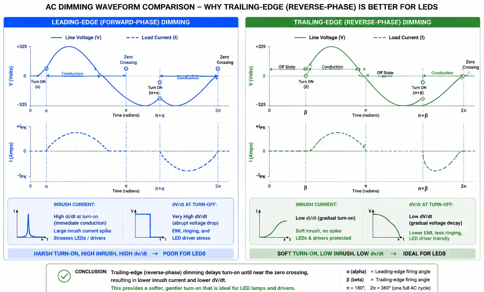
Trailing-Edge (Reverse-Phase) Dimming: This technique allows the full AC waveform to begin, then switches off before the natural zero-crossing. The softer turn-on characteristic produces lower inrush current and reduced EMI, making it inherently more compatible with capacitive and electronic loads like LED drivers. Trailing-edge dimmers typically use MOSFETs or IGBTs rather than TRIACs for the main switching element, though the control principle remains phase-based.
| Dimmer Type | Switching Device | Load Compatibility | Noise Performance | Typical Applications |
|---|---|---|---|---|
| Leading-Edge | TRIAC | Excellent for resistive (incandescent, halogen); poor for many LEDs | High inrush current; audible buzzing common | Legacy installations, incandescent lighting, resistive heaters |
| Trailing-Edge | MOSFET/IGBT | Excellent for electronic loads (LED drivers); compatible with capacitive loads | Low EMI; silent operation | Modern LED retrofits, electronic transformers, smart lighting systems |
| Universal | Hybrid circuit | Auto-detects load type | Variable depending on mode | New construction where load type may vary |
The selection between leading-edge and trailing-edge depends primarily on the load characteristics. For existing installations with incandescent or halogen loads, leading-edge TRIAC dimmers remain cost-effective. For LED retrofits or new installations with electronic drivers, trailing-edge dimmers provide superior compatibility and user experience, though at higher cost.
4. LED Compatibility Challenges and Solutions
The transition from incandescent to LED lighting has exposed fundamental compatibility issues with legacy TRIAC dimmer technology. These challenges stem from the fundamental difference between resistive incandescent loads and the electronic switch-mode power supplies inside LED drivers.
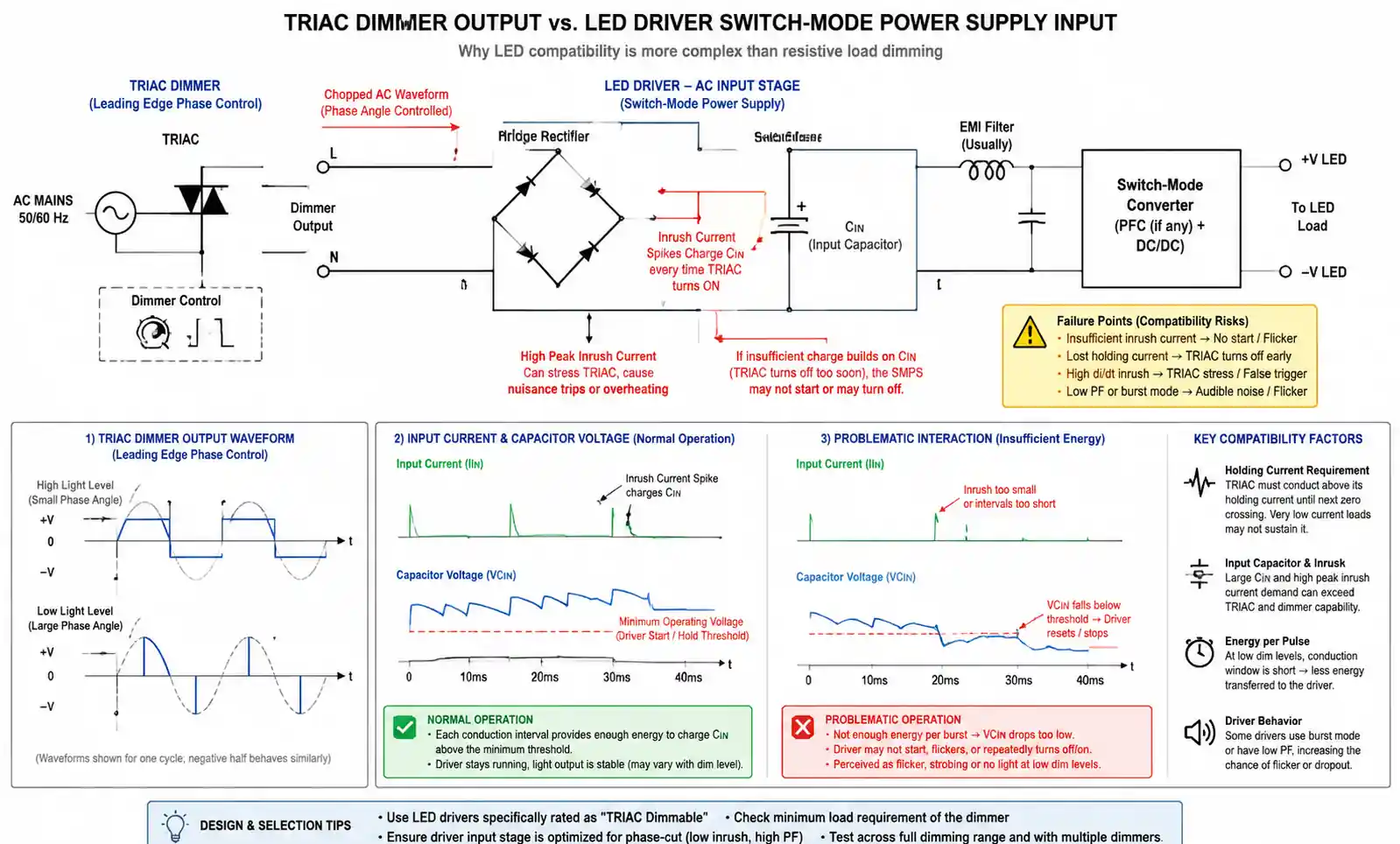
Minimum Load Requirements: Traditional TRIAC dimmers were designed for 300W-1000W incandescent loads. LED bulbs consuming 6W-15W fall far below the minimum load threshold, causing the dimmer's internal components (particularly the TRIAC holding current requirement) to malfunction. The result is flickering, flashing, or complete failure to illuminate at low dimming levels.
Inrush Current and Driver Interaction: LED drivers contain input capacitors that charge rapidly when the TRIAC triggers, creating high-frequency current spikes. These spikes can interfere with the dimmer's phase-angle control circuit, causing erratic dimming performance or audible buzzing. The problem intensifies when multiple LED fixtures share a single dimmer circuit.
No Industry Standards: Unlike 0-10V or DALI dimming protocols with defined specifications, no standardized requirements govern TRIAC dimmer-LED driver compatibility. Manufacturers test their products with specific dimmer models, leading to an unpredictable compatibility matrix. Two seemingly identical LED bulbs may behave differently on the same dimmer.
Practical Solutions:
-
Use LED-specific dimmers: Modern dimmers marketed for LED compatibility incorporate lower minimum loads (often 5W-10W) and modified control circuits that tolerate the non-resistive characteristics of LED drivers.
-
Load balancing: If dimming multiple LED fixtures, ensure the total load exceeds the dimmer's minimum threshold. Adding a single incandescent bulb to the circuit can stabilize operation, though this defeats energy-saving objectives.
-
Verify compatibility lists: Reputable LED and dimmer manufacturers publish compatibility matrices. Always cross-reference before specifying components for new installations or retrofits.
-
Consider trailing-edge dimmers: The softer turn-on characteristic of trailing-edge dimmers significantly improves LED compatibility compared to traditional leading-edge TRIAC devices.
-
Driver selection matters: When designing custom LED fixtures, specify drivers explicitly rated for TRIAC dimming with low holding current requirements (I_H < 10mA).
5. Design Considerations and Common Pitfalls
When designing TRIAC dimmer circuits or specifying dimmers for installations, several critical design considerations directly impact reliability and performance.
EMI/RFI Suppression: The abrupt switching action of TRIACs generates high-frequency noise that can interfere with nearby electronics, radio receivers, and communication equipment. Effective suppression requires RC snubber circuits across the TRIAC terminals and LC filters on the line input. For residential applications, ensure compliance with FCC Part 15 (North America) or EN 55015 (Europe) conducted and radiated emission limits.
Thermal Management: Despite TRIACs being more efficient than resistive dimming, power dissipation remains significant at high loads. For a 500W load at 120V (4.17A RMS), assuming a 1.2V forward drop, the TRIAC dissipates approximately 5W. Without adequate heatsinking, junction temperature can exceed ratings, leading to thermal runaway or premature failure. Always calculate worst-case dissipation and verify heatsink thermal resistance maintains junction temperature below 125°C.
Zero-Crossing Detection: Advanced dimmer designs incorporate zero-crossing detection circuits that synchronize control actions with the AC waveform's natural zero points. This technique eliminates the need for timing capacitor discharge circuits and reduces EMI. However, it requires additional circuitry and careful PCB layout to prevent noise coupling.
Load Type Matching: A common mistake is assuming a dimmer designed for incandescent loads will automatically work with other load types. Inductive loads (motors, transformers) require dimmers with higher dV/dt ratings and snubber networks to prevent false triggering. Capacitive loads (electronic transformers, LED drivers) need trailing-edge designs to avoid inrush current issues.
Safety Isolation: In wall-mounted dimmer applications, ensure proper isolation between the AC line circuitry and any user-accessible control interfaces. If using microcontroller-based control, employ optoisolators (e.g., MOC3021, MOC3041) to maintain isolation between low-voltage control and high-voltage switching sections.
| Design Pitfall | Symptoms | Prevention Strategy |
|---|---|---|
| Insufficient heatsinking | Dimmer overheating, premature failure, thermal shutdown | Calculate power dissipation; use thermal simulation; verify heatsink R_θJA |
| Missing EMI suppression | Radio interference, LED flicker, electronic device malfunction | Add RC snubber (0.1μF + 100Ω), line filter inductor, ferrite beads |
| Incorrect load rating | Dimmer failure, tripped breakers, fire hazard | Verify both incandescent and LED load ratings; derate by 20% for inductive loads |
| No minimum load handling | LED flicker at low dimming, inconsistent turn-on | Use LED-compatible dimmers with <10W minimum load rating |
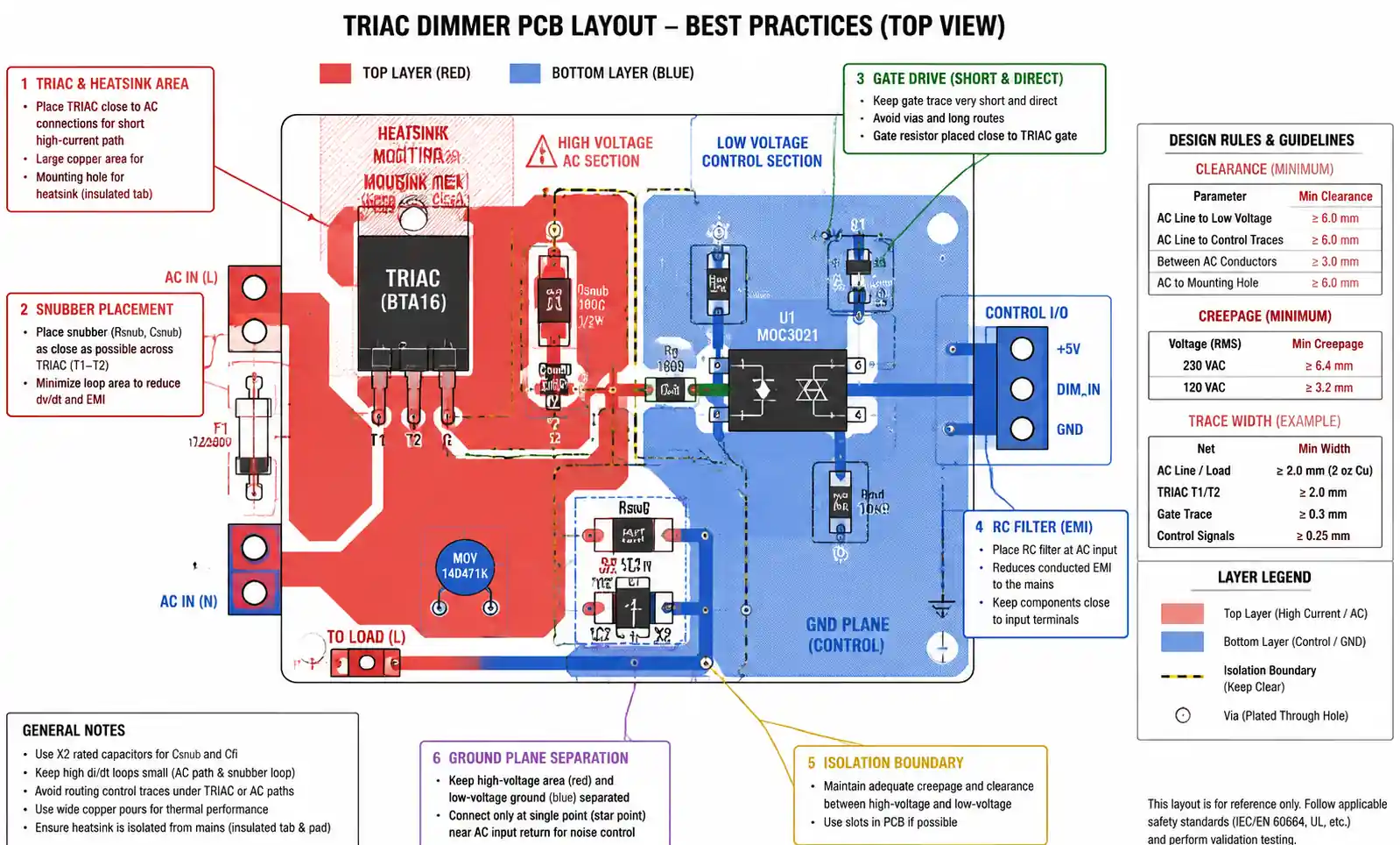
| Poor PCB layout | False triggering, noise sensitivity, erratic operation | Keep gate drive traces short; ground plane separation; proper snubber placement |
| Missing transient protection | TRIAC failure from line surges | Add MOV across AC input; consider TVS diodes on gate circuit |
The most frequently overlooked issue is PCB layout for the gate drive circuit. Keep gate traces short and route them away from high dV/dt switching nodes. A poorly placed trace can couple switching noise back into the gate, causing retriggering or erratic dimming behavior.
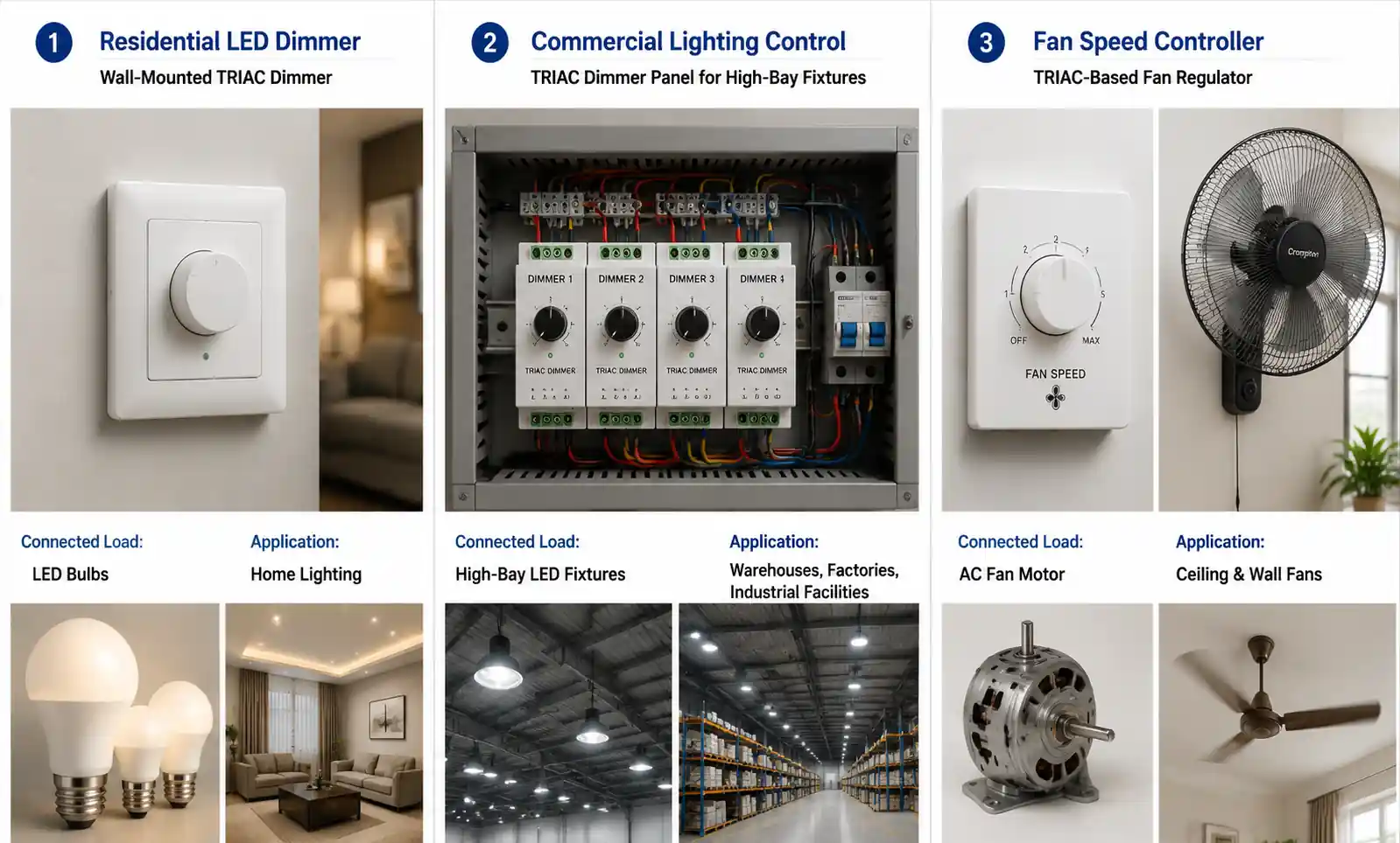
6. Application-Specific Selection Criteria
Different applications demand different dimmer characteristics. Selecting the optimal TRIAC dimmer configuration requires understanding the specific performance requirements and constraints of your use case.
Residential Lighting: For home lighting retrofits, prioritize user experience factors—smooth dimming range (ideally 1-100% without flicker or dropout), silent operation, and compatibility with a wide range of LED bulb brands. Universal dimmers that auto-detect load type provide the most flexibility in mixed-technology households where some fixtures remain incandescent while others transition to LED. Look for dimmers with adjustable minimum brightness settings to accommodate different LED driver designs.
Commercial Lighting: In commercial installations with larger fixture counts, focus on load capacity and heat dissipation. Multi-gang dimmer installations in enclosed wall boxes require aggressive derating—reduce the per-dimmer load rating by 30-40% when installing multiple dimmers side-by-side. Consider dimmers with built-in active cooling or specify larger junction boxes to improve air circulation. For hospitality and retail applications, verify smooth dimming at the 10-30% range where most ambiance lighting operates.
Stage and Theatrical Lighting: Professional dimming applications require dimmers with linear dimming curves, high reliability, and compatibility with professional control protocols (DMX512). While TRIAC dimmers remain common in legacy theatrical installations, modern designs increasingly favor solid-state relay (SSR) or sine-wave dimming for tungsten fixtures, reserving TRIAC control for specific legacy equipment.
Motor Speed Control: When controlling inductive loads like fans or small motors, TRIAC dimmers must include additional protection against the high dV/dt generated by inductive kickback. Select dimmers with snubber networks and higher dV/dt ratings (>200 V/μs). Note that TRIAC dimming reduces motor torque and efficiency—for precision motor control, consider variable frequency drives (VFDs) instead.
IoT and Smart Home Integration: Modern installations increasingly require dimmers with digital control interfaces. While some smart dimmers retain internal TRIAC switching and add wireless control (Zigbee, Z-Wave, Wi-Fi), others use the dimmer as a front-end to protocol-based systems (DALI, DMX). For new smart home construction, evaluate whether TRIAC dimming is the optimal long-term solution or if alternative protocols (0-10V, DALI) provide better future compatibility and fixture selection.
| Application | Priority Parameters | Recommended Dimmer Type | Key Considerations |
|---|---|---|---|
| LED Retrofit (Residential) | Compatibility range, minimum load <10W, smooth curve | Universal or trailing-edge | Verify with actual LED bulbs before bulk purchase; adjustable minimum settings |
| Incandescent (Residential) | Cost, reliability, silent operation | Leading-edge TRIAC | Standard choice; ensure adequate load rating for fixture count |
| Commercial (High Bay) | Load capacity >600W, thermal performance | Industrial-grade leading-edge or modular dimmer banks | Derating for multi-gang installations; thermal management critical |
| Hospitality/Retail | Smooth 10-30% dimming, silent operation, aesthetics | Trailing-edge or universal | User experience critical; demo with actual fixtures before specifying |
| Stage/Theater | Linear dimming curve, DMX compatibility | Professional dimmer packs with TRIAC or SSR | Consider maintenance access; compatibility with legacy tungsten fixtures |
| Motor Control | High dV/dt rating, snubber network, overload protection | Industrial motor-rated dimmer | TRIAC appropriate only for simple fan control; use VFD for precision applications |
When specifying for new construction, consider the total cost of ownership, not just initial dimmer cost. A $30 universal dimmer that works reliably with any LED bulb the homeowner chooses represents better value than a $15 basic dimmer that requires bulb compatibility verification and potential field callbacks.
7. FAQ
Q: What is the difference between a TRIAC dimmer and a standard light switch?
A: A standard switch provides only on/off control by mechanically opening or closing the circuit. A TRIAC dimmer actively modulates the AC waveform by controlling when the TRIAC conducts during each half-cycle, allowing continuous adjustment of delivered power. This phase-angle control enables variable brightness or speed without the energy waste of resistive dimming methods.
Q: Can I use a leading-edge TRIAC dimmer with LED bulbs?
A: It depends on the specific LED bulb's driver design. Many modern LED bulbs include TRIAC-compatible drivers, but compatibility is unpredictable due to lack of industry standards. Leading-edge dimmers work best with resistive incandescent loads. For LED applications, trailing-edge or LED-specific dimmers provide significantly better compatibility and reduce flickering, buzzing, and premature LED failure.
Q: Why does my LED bulb flicker at low dimming levels?
A: Low-level flicker typically results from the LED driver's holding current falling below the TRIAC's minimum holding current (I_H) requirement. When load current drops too low, the TRIAC cannot maintain conduction and repeatedly drops out. Solutions include using LED-specific dimmers with lower minimum loads, adding additional LED fixtures to increase total circuit current, or specifying LED bulbs explicitly rated for TRIAC dimming with low holding current requirements.
Q: How do I calculate the required dimmer load rating for multiple LED fixtures?
A: Sum the wattage of all LED fixtures on the circuit, then verify this total falls within the dimmer's LED load rating (not the incandescent rating). Add 20% safety margin for inrush current. For example, eight 10W LED bulbs (80W total) require a dimmer rated for at least 100W of LED load. Note that LED ratings are often lower than incandescent ratings on the same dimmer due to driver interaction effects.
Q: What causes buzzing noise from TRIAC dimmers?
A: Buzzing typically originates from two sources: magnetic components (transformers, chokes) vibrating due to the chopped waveform, or mechanical resonance in the dimmer itself. Leading-edge dimmers produce more buzzing due to higher inrush currents. Solutions include switching to trailing-edge dimmers, adding ferrite beads to reduce high-frequency noise, ensuring tight mechanical assembly of the dimmer, or in severe cases, replacing magnetic transformers with electronic types.
Q: Are TRIAC dimmers compatible with smart home systems?
A: Standard TRIAC dimmers operate independently without smart home integration. However, many manufacturers offer smart dimmers that combine TRIAC switching with wireless protocols (Zigbee, Z-Wave, Wi-Fi) for remote control and automation. When selecting smart dimmers, verify both the TRIAC specifications for electrical compatibility and the wireless protocol for ecosystem compatibility (e.g., HomeKit, Alexa, Google Home).
Q: How do I troubleshoot a TRIAC dimmer that stopped working?
A: Start by verifying line voltage is present at the dimmer input. Check for tripped breakers or blown fuses. Measure TRIAC forward voltage drop—an open TRIAC shows line voltage across it; a shorted TRIAC shows near-zero voltage and trips the breaker. Verify the gate drive circuit is triggering by measuring gate current or voltage during dimming adjustment. Common failure modes include TRIAC burnout from overcurrent, failed snubber components, or damaged gate drive circuitry from transients.
Q: What safety certifications should I look for in TRIAC dimmers?
A: For North American installations, verify UL 1472 (solid-state dimming controls) or CSA C22.2 certification. European markets require CE marking with compliance to EN 60669-2-1 (switches for household installations). Additionally, check for FCC Part 15 or EN 55015 compliance for electromagnetic interference limits. For commercial installations, verify the dimmer meets local electrical codes regarding load ratings, enclosure types, and accessibility requirements.
8. Conclusion
TRIAC dimmers remain a cost-effective solution for AC power control in residential and commercial applications, particularly for incandescent and halogen loads. However, the transition to LED lighting requires careful attention to compatibility factors that didn't exist in the incandescent era.
For new LED installations, prioritize trailing-edge or universal dimmers with explicit LED compatibility ratings and minimum loads below 10W. When retrofitting existing dimmers, test compatibility with actual LED fixtures before committing to large purchases. In applications where TRIAC compatibility proves problematic, consider alternative dimming protocols like 0-10V or DALI that offer predictable LED compatibility through standardized specifications.
For design engineers developing custom dimming circuits, focus on thermal management, EMI suppression, and proper selection of TRIAC parameters (especially holding current and dV/dt ratings) matched to the intended load characteristics. Thorough testing across the full dimming range with representative loads is essential—benchtop testing with resistive loads does not predict real-world performance with electronic LED drivers.
If you're specifying TRIAC dimmers for a project, verify compatibility between the specific dimmer model and actual LED fixtures through manufacturer cross-reference tools or physical testing. For technical support on component selection, download datasheets for specific TRIAC devices or consult with field application engineers who can recommend proven combinations for your application requirements.