




Op-Amp vs Differential Amplifier vs Instrumentation Amplifier: Complete Comparison Guide
Choosing the right amplifier for your electronic circuit can make or break your design. Whether you're working on sensor signal conditioning, audio processing, or precision measurement systems, understanding the differences between operational amplifiers (op-amps), differential amplifiers, and instrumentation amplifiers is crucial for optimal performance.
This comprehensive guide breaks down each amplifier type, their unique characteristics, practical applications, and helps you decide which one fits your specific needs.
Table of Contents
- What Are Amplifiers and Why Do They Matter?
- Operational Amplifier (Op-Amp) Explained
- Differential Amplifier Fundamentals
- Instrumentation Amplifier Deep Dive
- Key Differences: Side-by-Side Comparison
- When to Use Each Amplifier Type
- Common Applications in Modern Electronics
- Design Considerations and Best Practices
- Frequently Asked Questions
- Conclusion: Making the Right Choice
1. What Are Amplifiers and Why Do They Matter?
Amplifiers are fundamental building blocks in electronic circuits that increase the amplitude of electrical signals. In modern electronics, signals from sensors, microphones, or other sources are often too weak to be processed directly. Amplifiers boost these signals to usable levels while maintaining signal integrity.
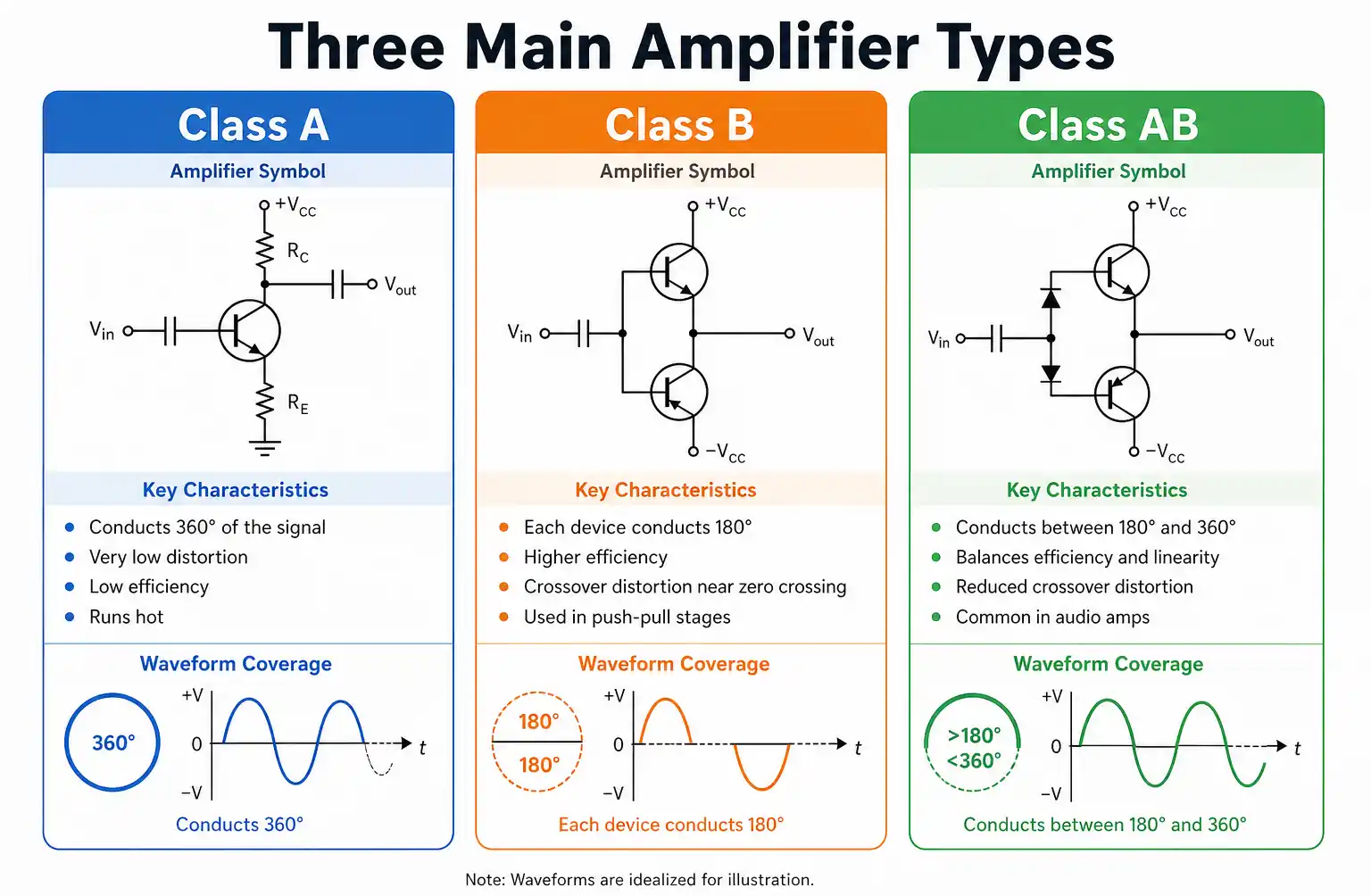
The three main amplifier types—operational amplifiers, differential amplifiers, and instrumentation amplifiers—each serve distinct purposes based on factors like signal level, noise sensitivity, input impedance requirements, and precision needs.
Understanding which amplifier to use impacts:
- Signal quality: Noise rejection and signal fidelity
- Power consumption: Efficiency in battery-powered devices
- Cost: Component count and complexity
- Performance: Accuracy and bandwidth requirements
2. Operational Amplifier (Op-Amp) Explained
What Is an Op-Amp?
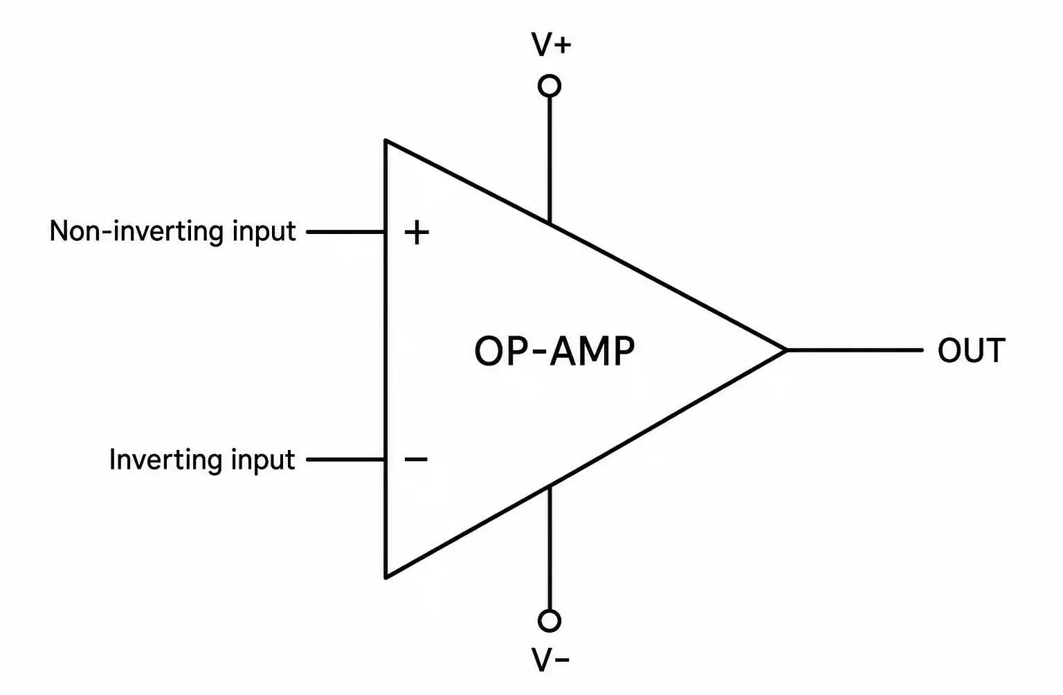
An operational amplifier is a high-gain, DC-coupled voltage amplifier with differential inputs and typically a single-ended output. Op-amps are the most versatile and widely used amplifier type in analog electronics.
Key Characteristics
Input Configuration: Op-amps have two inputs—inverting (-) and non-inverting (+). The output voltage is proportional to the difference between these inputs multiplied by the open-loop gain.
High Open-Loop Gain: Typical op-amps have open-loop gains ranging from 100,000 to over 1,000,000 (100 dB to 120 dB). This high gain enables precise control through negative feedback.
Input Impedance: Modern op-amps feature very high input impedance (typically 1 MΩ to 1 TΩ), meaning they draw minimal current from the source.
Output Impedance: Low output impedance (typically 10 Ω to 100 Ω) allows op-amps to drive loads effectively.
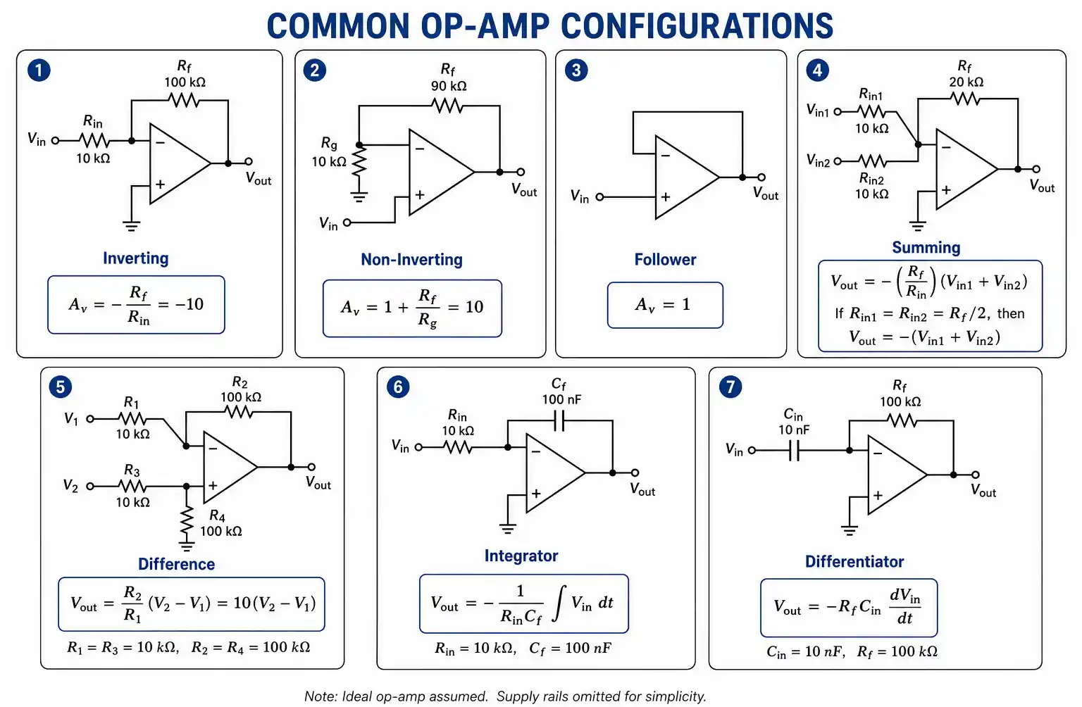
Common Op-Amp Configurations
- Inverting Amplifier: Output is inverted and scaled version of input
- Non-Inverting Amplifier: Output is in-phase with input
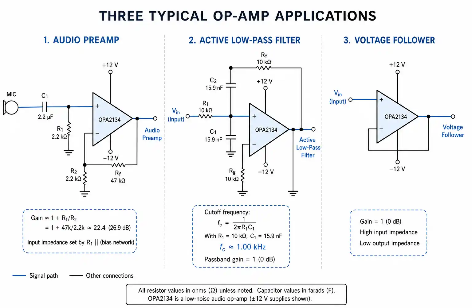
- Voltage Follower (Buffer): Unity gain with high input impedance
- Summing Amplifier: Adds multiple input signals
- Integrator/Differentiator: Performs mathematical operations
Typical Applications
- Audio amplification and mixing
- Active filters (low-pass, high-pass, band-pass)
- Signal conditioning
- Voltage comparators
- Oscillators and waveform generators
- Analog computation
Advantages
- Extremely versatile with multiple configurations
- Wide availability and low cost
- Simple external component requirements
- Excellent for general-purpose amplification
Limitations
- Moderate common-mode rejection ratio (CMRR: 70-90 dB)
- Susceptible to noise in high-impedance environments
- Gain accuracy depends on external resistor precision
- Limited performance with very small differential signals
3. Differential Amplifier Fundamentals
What Is a Differential Amplifier?
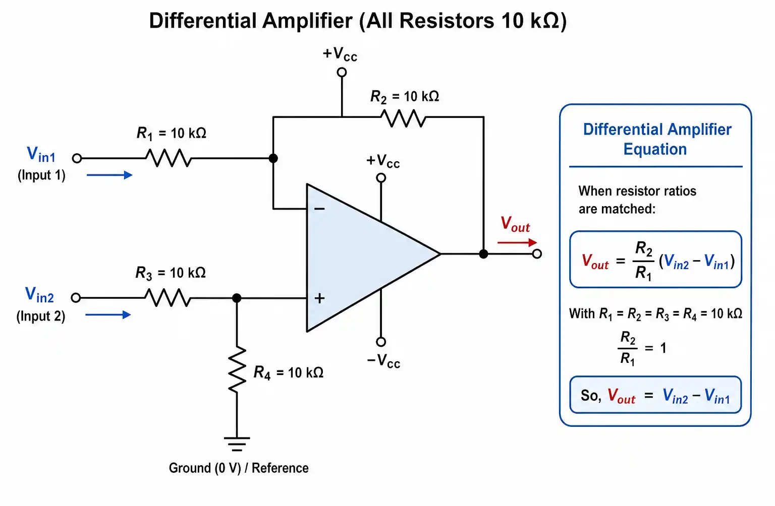
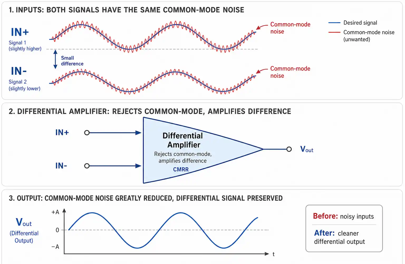
A differential amplifier amplifies the voltage difference between two input signals while rejecting signals common to both inputs. This makes it excellent for noise rejection in environments with electrical interference.
Key Characteristics
Dual Input Design: Accepts two input signals and amplifies only their difference, effectively canceling out common-mode noise.
Common-Mode Rejection: The ability to reject signals that appear on both inputs simultaneously is measured by CMRR, typically 60-80 dB for basic differential amplifiers.
Balanced Operation: Both inputs have similar impedance characteristics, making the circuit more immune to ground noise and interference.
How It Works
The differential amplifier output is:
Vout = Ad × (V+ - V-)
Where:
- Ad = differential gain
- V+ = non-inverting input voltage
- V- = inverting input voltage
Any signal common to both inputs (common-mode signal) is ideally rejected completely.
Circuit Configurations
- Single Op-Amp Differential Amplifier: Simple but limited CMRR
- Dual Op-Amp Differential Amplifier: Improved performance
- Long-Tailed Pair: Classic transistor-based design
Typical Applications
- Balanced audio signal processing
- Noise rejection in industrial environments
- Sensor signal conditioning
- ECG and biomedical signal acquisition
- Communication systems
Advantages
- Good common-mode noise rejection
- Balanced input structure
- Suitable for noisy environments
- Can be built with discrete components or op-amps
Limitations
- CMRR depends heavily on resistor matching
- Input impedance may not be high enough for some sensors
- Gain adjustment requires changing multiple resistors
- Performance degrades with component tolerance
4. Instrumentation Amplifier Deep Dive
What Is an Instrumentation Amplifier?
An instrumentation amplifier (in-amp or INA) is a specialized differential amplifier designed for precision measurement applications. It combines high input impedance, excellent CMRR, and easy gain adjustment in a single package.
Key Characteristics
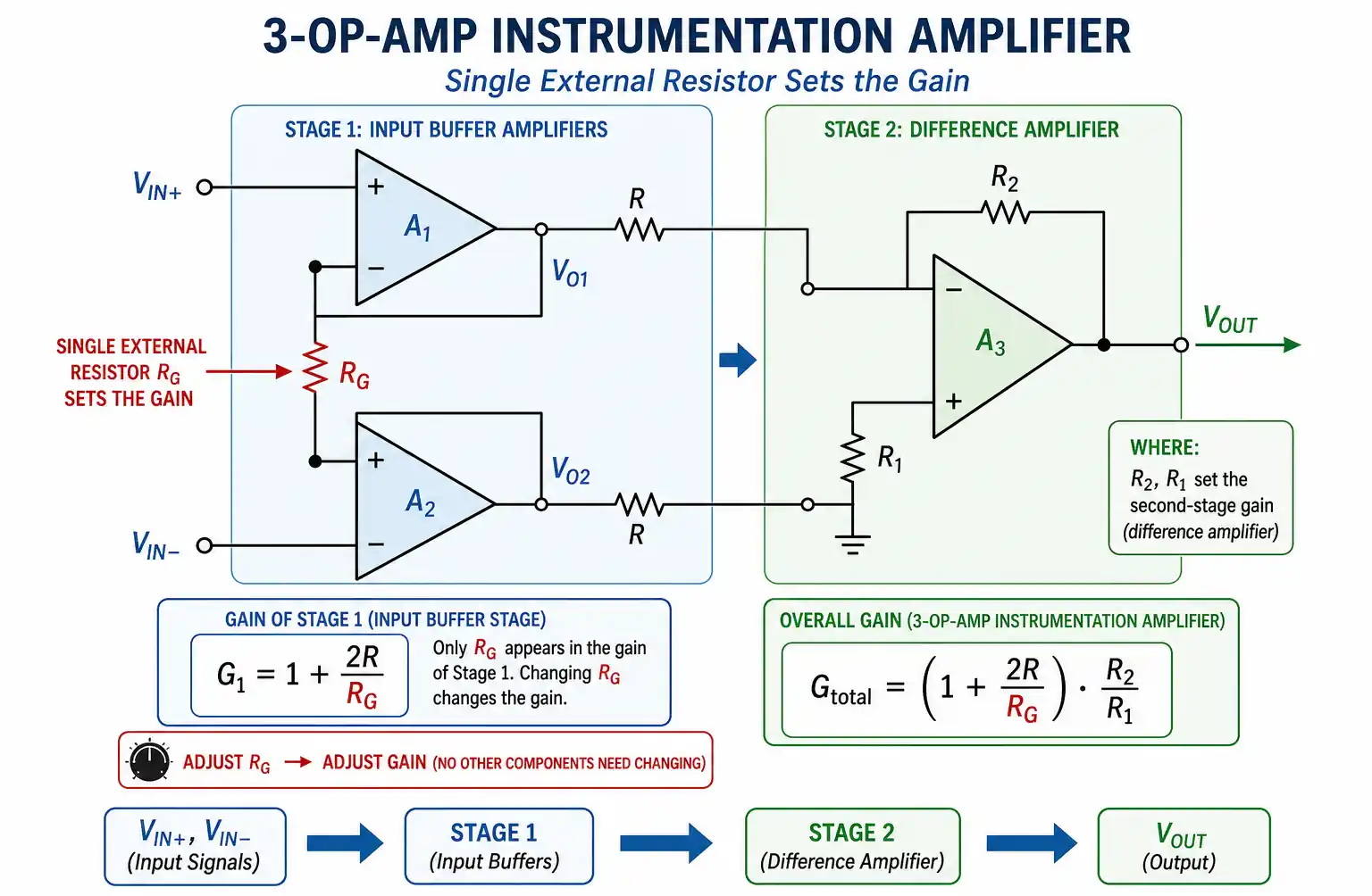
Three Op-Amp Architecture: The classic instrumentation amplifier uses three op-amps—two input buffers and one differential stage—providing superior performance.
Extremely High Input Impedance: Typically 10 GΩ or higher, ensuring minimal loading on the signal source.
Exceptional CMRR: 90-120 dB or higher, far exceeding standard differential amplifiers.
Single Resistor Gain Control: Gain can be precisely set with a single external resistor, simplifying design and calibration.
Matched Input Characteristics: Both inputs have identical impedance, ensuring balanced operation.
How It Works
The instrumentation amplifier architecture consists of:
- Input Stage: Two non-inverting amplifiers with high input impedance buffer the input signals
- Differential Stage: A precision differential amplifier extracts the difference signal
- Gain Setting: A single resistor (Rgain) between the input stage op-amps sets the overall gain
Gain Formula: G = 1 + (2R/Rgain)
Where R is the internal resistor value (specified in datasheet).
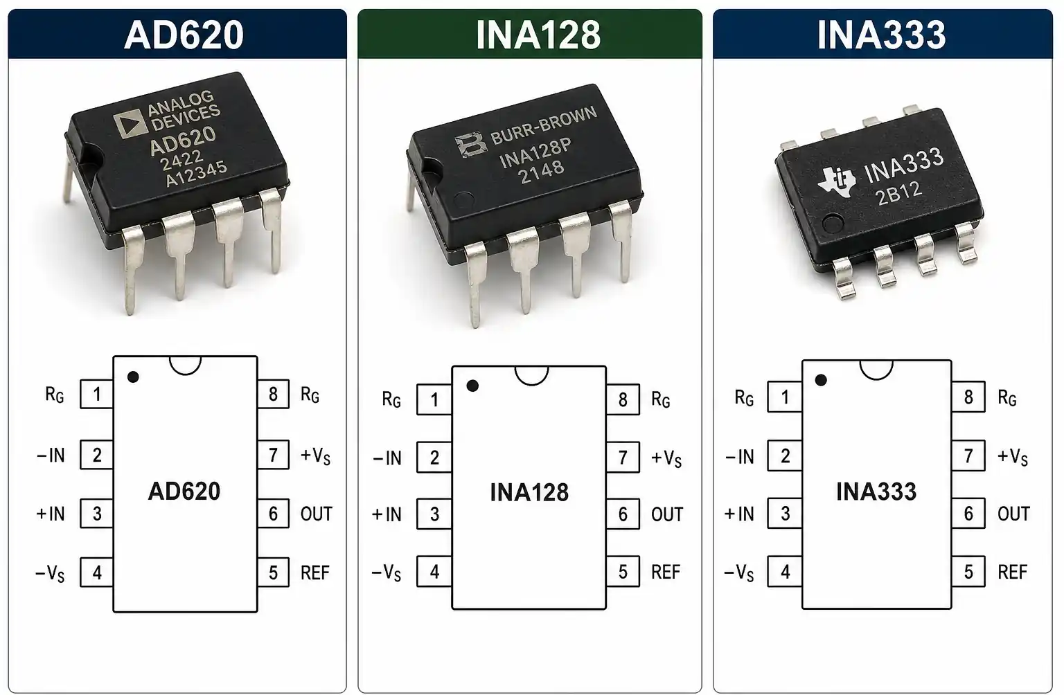
Popular Instrumentation Amplifier ICs
- AD620: Low cost, single supply operation
- INA128: High precision, low noise
- INA333: Ultra-low power consumption
- AD8221: Rail-to-rail output
- LT1167: High-speed performance
Typical Applications
- Medical instrumentation (ECG, EEG, EMG)
- Strain gauge and load cell amplification
- Thermocouple signal conditioning
- Bridge sensor amplification (Wheatstone bridge)
- Precision data acquisition systems
- Industrial process control
- Seismic and vibration monitoring
Advantages
- Highest CMRR among amplifier types
- Very high input impedance (minimal source loading)
- Easy gain adjustment with single resistor
- Excellent DC precision and low offset voltage
- Superior noise rejection
- Matched input characteristics
Limitations
- Higher cost compared to op-amps
- More complex internal circuitry
- Limited bandwidth compared to simple op-amps
- Requires careful PCB layout for optimal performance
- Power consumption higher than basic op-amps
5. Key Differences: Side-by-Side Comparison
| Feature | Op-Amp | Differential Amplifier | Instrumentation Amplifier |
|---|---|---|---|
| Input Impedance | High (1 MΩ - 1 TΩ) | Moderate (10 kΩ - 100 kΩ) | Very High (>10 GΩ) |
| CMRR | 70-90 dB | 60-80 dB | 90-120 dB |
| Gain Setting | External resistors | Multiple resistor pairs | Single resistor |
| Input Balance | Asymmetric | Symmetric | Perfectly matched |
| Cost | Low ($0.10 - $2) | Low to Moderate | Moderate to High ($2 - $10) |
| Complexity | Simple | Moderate | Complex (integrated) |
| Noise Performance | Good | Better | Best |
| Precision | Moderate | Good | Excellent |
| Bandwidth | Wide (MHz range) | Moderate | Limited (kHz to low MHz) |
| Best For | General amplification | Noise rejection | Precision measurement |
CMRR Comparison Explained
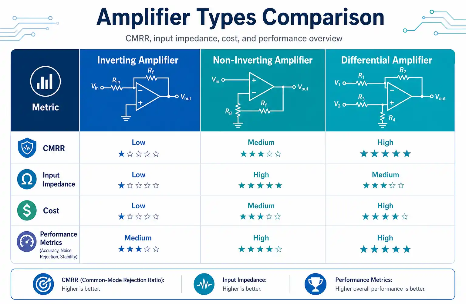
Common-Mode Rejection Ratio (CMRR) measures how well an amplifier rejects signals common to both inputs:
- Op-Amp (70-90 dB): Adequate for most general applications
- Differential Amplifier (60-80 dB): Good, but depends on resistor matching
- Instrumentation Amplifier (90-120 dB): Exceptional, ideal for noisy environments
A CMRR of 100 dB means common-mode signals are attenuated by 100,000 times compared to differential signals.
Input Impedance Impact
Op-Amp: High enough for most voltage sources but may load high-impedance sensors.
Differential Amplifier: Input impedance determined by external resistors; may be too low for some applications.
Instrumentation Amplifier: Extremely high input impedance makes it ideal for sensors like strain gauges, thermocouples, and biomedical electrodes.
6. When to Use Each Amplifier Type
Choose an Op-Amp When:
- You need versatile, general-purpose amplification
- Cost is a primary concern
- Wide bandwidth is required
- The application involves active filters, oscillators, or comparators
- Signal sources have low impedance
- Moderate noise levels are acceptable
- You need multiple circuit configurations (inverting, non-inverting, summing)
Example Scenarios:
- Audio preamplifiers
- Active filter circuits
- Voltage followers for impedance matching
- Signal generators and oscillators
Choose a Differential Amplifier When:
- You need to reject common-mode noise
- Working with balanced signal sources
- The environment has significant electrical interference
- Moderate CMRR (60-80 dB) is sufficient
- You want a cost-effective noise rejection solution
- Input impedance requirements are moderate
Example Scenarios:
- Balanced audio line receivers
- Industrial sensor interfaces with moderate noise
- Communication system receivers
- ECG front-end circuits (basic applications)
Choose an Instrumentation Amplifier When:
- Maximum precision is required
- Signal sources have very high impedance (sensors)
- Exceptional CMRR (>90 dB) is needed
- Working with very small differential signals (μV to mV range)
- Easy gain adjustment is important
- DC accuracy and low drift are critical
- The application justifies higher cost
Example Scenarios:
- Medical device signal acquisition
- Strain gauge and load cell measurements
- Thermocouple temperature sensing
- Wheatstone bridge amplification
- Precision data acquisition systems
- Seismic monitoring equipment
7. Common Applications in Modern Electronics
Medical and Biomedical Instrumentation
Instrumentation amplifiers dominate this field due to their exceptional noise rejection and high input impedance.
- ECG (Electrocardiogram): Amplifies microvolt-level heart signals while rejecting 50/60 Hz power line interference
- EEG (Electroencephalogram): Brain signal monitoring requires ultra-low noise
- EMG (Electromyogram): Muscle activity measurement
- Pulse oximetry: Optical sensor signal conditioning
Industrial Sensor Applications
Instrumentation amplifiers are preferred for precision measurements:
- Strain gauges: Bridge circuit amplification for force, pressure, and weight measurement
- Load cells: High-precision weighing systems
- Pressure transducers: Industrial process monitoring
- Temperature sensors: RTD and thermocouple signal conditioning
Differential amplifiers work well for:
- Proximity sensors in noisy factory environments
- Motor current sensing
- Industrial control systems
Audio and Consumer Electronics
Op-amps are the workhorse for audio applications:
- Microphone preamplifiers
- Headphone amplifiers
- Mixing consoles
- Equalizers and tone controls
- Active crossover networks
Differential amplifiers are used in:
- Balanced audio line receivers
- Professional audio equipment
- Noise-canceling circuits
Automotive Electronics
Modern vehicles use all three amplifier types:
- Instrumentation amplifiers: Airbag sensors, crash detection, battery monitoring
- Differential amplifiers: CAN bus receivers, sensor interfaces
- Op-amps: Audio systems, climate control, general signal processing
Communication Systems
- Op-amps: Modulation circuits, filters, AGC (Automatic Gain Control)
- Differential amplifiers: Balanced line receivers, RF signal processing
- Instrumentation amplifiers: Precision RF power measurement
8. Design Considerations and Best Practices
Power Supply Considerations
Single Supply vs. Dual Supply:
- Dual supply (±5V, ±15V): Simplifies design, allows signals to swing both positive and negative
- Single supply (3.3V, 5V): Required for battery-powered and modern digital systems
Many modern amplifiers support rail-to-rail operation, maximizing signal swing in single-supply designs.
Noise Reduction Techniques
- PCB Layout: Keep input traces short and away from digital signals
- Grounding: Use star grounding for precision circuits
- Shielding: Shield sensitive input traces
- Bypass Capacitors: Place close to power pins (0.1 μF ceramic + 10 μF electrolytic)
- Input Filtering: Add RC filters to reduce high-frequency noise
Gain and Bandwidth Trade-offs
All amplifiers have a gain-bandwidth product (GBW) that limits performance:
- Higher gain reduces available bandwidth
- For op-amps: Bandwidth = GBW / Gain
- Instrumentation amplifiers typically have lower GBW than general-purpose op-amps
Example: An op-amp with 1 MHz GBW configured for gain of 100 has a bandwidth of only 10 kHz.
Offset Voltage and Drift
Input Offset Voltage: The voltage difference between inputs required to make output zero.
- Op-amps: 0.5 mV to 5 mV (standard), <100 μV (precision)
- Instrumentation amplifiers: <50 μV to <500 μV
Temperature Drift: How offset voltage changes with temperature (μV/°C).
For precision DC measurements, choose amplifiers with low offset and drift specifications.
Component Selection Tips
- Resistor Tolerance: Use 0.1% or better for precision differential and instrumentation amplifier circuits
- Capacitor Type: Use low-leakage types (film, ceramic) for critical applications
- PCB Material: FR-4 is adequate for most applications; use Rogers or Teflon for high-frequency designs
- Thermal Management: Ensure adequate cooling for high-power applications
9. Frequently Asked Questions
Can I use an op-amp as a differential amplifier?
Yes, you can configure an op-amp as a differential amplifier using four external resistors. However, performance will be limited compared to a dedicated instrumentation amplifier, particularly in terms of CMRR and input impedance. Resistor matching is critical—even 1% tolerance can significantly degrade CMRR.
What's the main advantage of an instrumentation amplifier over a differential amplifier?
The main advantages are:
- Much higher input impedance (GΩ vs. kΩ range)
- Superior CMRR (90-120 dB vs. 60-80 dB)
- Single resistor gain control (easier to adjust and calibrate)
- Matched input characteristics (better balance and symmetry)
Are instrumentation amplifiers always better than op-amps?
No. Instrumentation amplifiers excel at precision differential measurements but are more expensive, have lower bandwidth, and consume more power. For general-purpose amplification, filtering, or applications where high CMRR isn't critical, standard op-amps are more cost-effective and versatile.
How do I choose the right CMRR for my application?
Consider your noise environment:
- 60-70 dB: Adequate for low-noise lab environments
- 80-90 dB: Good for typical industrial applications
- 100+ dB: Required for medical devices, precision sensors, and high-noise environments
Remember: CMRR of 80 dB means common-mode noise is reduced by 10,000 times.
Can I use these amplifiers with single-supply operation?
Yes, many modern amplifiers support single-supply operation. Look for:
- Rail-to-rail input/output specifications
- Low voltage operation (3.3V, 5V)
- Ground-referenced inputs capability
Single-supply operation requires careful biasing to keep signals within the valid input range.
What causes CMRR degradation in real circuits?
Main factors:
- Resistor mismatch in differential amplifier circuits
- PCB layout issues (unequal trace lengths, ground loops)
- Source impedance imbalance between inputs
- Frequency effects (CMRR decreases at higher frequencies)
- Temperature variations affecting component values
How important is input impedance for sensor applications?
Very important. Low input impedance can:
- Load the sensor, changing its output
- Introduce measurement errors
- Reduce sensitivity
- Cause signal distortion
High-impedance sensors (strain gauges, pH electrodes, biomedical electrodes) require amplifiers with very high input impedance—making instrumentation amplifiers the ideal choice.
10. Conclusion: Making the Right Choice
Selecting between op-amps, differential amplifiers, and instrumentation amplifiers depends on your specific application requirements:
Choose Op-Amps for versatile, cost-effective general-purpose amplification where moderate noise performance is acceptable and you need flexibility in circuit configuration.
Choose Differential Amplifiers when you need balanced inputs and good common-mode noise rejection in moderately noisy environments, and cost is a consideration.
Choose Instrumentation Amplifiers for precision measurement applications requiring exceptional CMRR, very high input impedance, and accurate amplification of small differential signals, especially with high-impedance sensors.
Understanding these differences empowers you to design more effective circuits, avoid common pitfalls, and achieve optimal performance for your specific application. Whether you're designing medical devices, industrial sensors, audio equipment, or data acquisition systems, selecting the right amplifier type is fundamental to success.
For most precision sensor applications in 2026, integrated instrumentation amplifier ICs offer the best combination of performance, ease of use, and reliability—making them the go-to choice for demanding measurement tasks.
