



USB Type-C Controller and Power Delivery IC Selection
If you need to design reliable USB Type-C interfaces with power delivery capabilities, then you will need USB-C controllers that handle power negotiation, CC logic, VBUS control, and alternate modes correctly. Modern USB Type-C controller ICs support USB PD 3.1 specifications enabling up to 240W power delivery, USB4 data transfer, and alternate modes like DisplayPort and Thunderbolt. Choosing the right controller depends on your power requirements, data speed needs, alternate mode support, and protection features.
Table of Contents
- What is USB Type-C Controller?
- USB Power Delivery Standards Overview
- Key Technical Features
- USB Type-C Controller Types
- Alternate Modes Support
- USB4 Integration
- Controller IC Comparison
- Selection Criteria
- Procurement Considerations
- Conclusion
- FAQ
What is USB Type-C Controller?
USB Type-C controllers are integrated circuits that manage the electrical and protocol functions of USB-C ports. These ICs handle configuration channel (CC) logic, power delivery negotiation, cable orientation detection, and role management between host and device. According to USB-C hardware design standards, modern controllers integrate VBUS control, protection circuits, and support for alternate modes in a single chip.
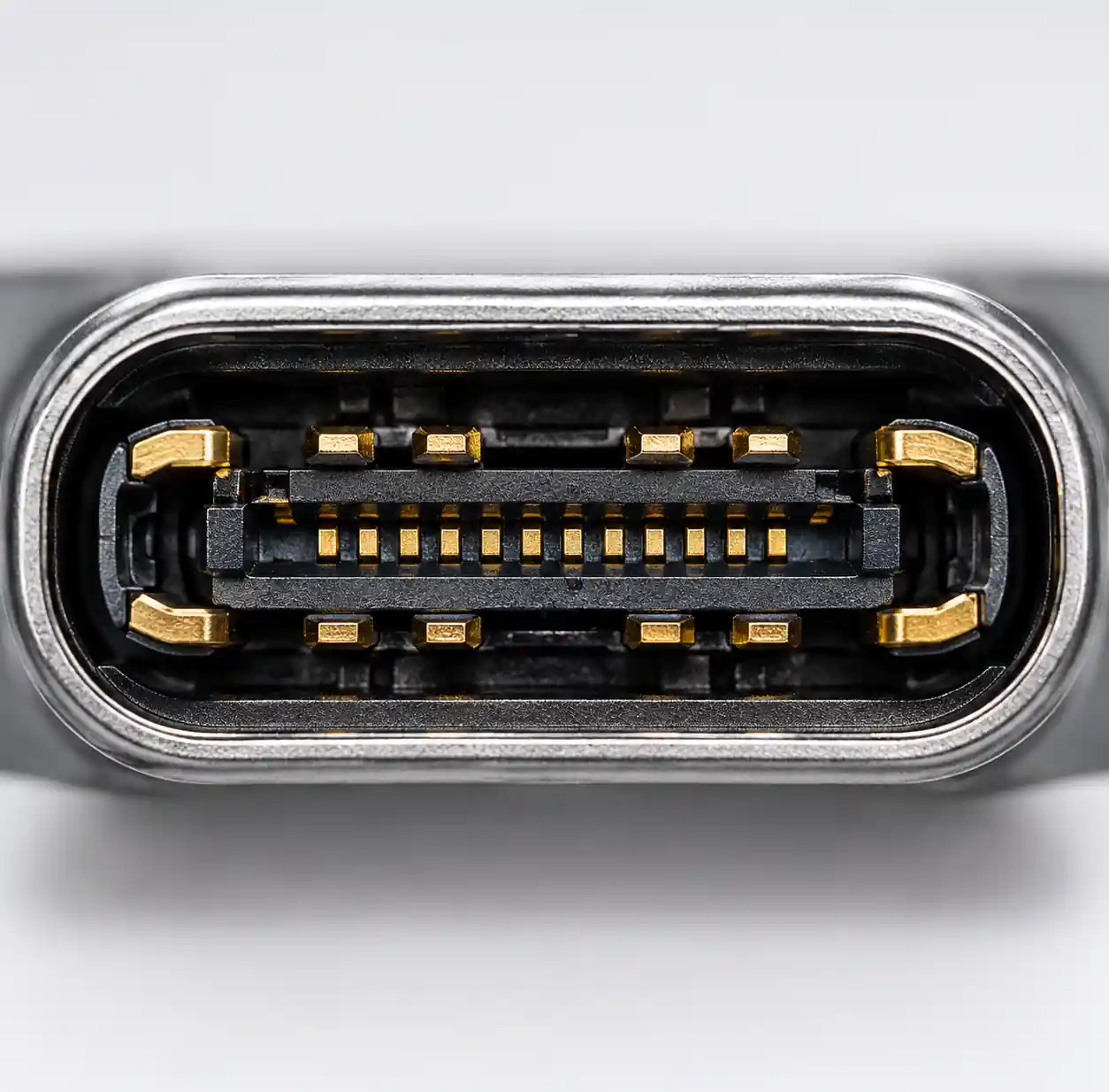 USB Type-C port cross-section showing CC pins and VBUS power delivery paths
The controller continuously monitors CC pins to detect cable attachment, determine cable orientation, and establish the appropriate power delivery profile. You can use Type-C controllers in consumer electronics, industrial equipment, automotive systems, and computing devices requiring flexible power and data connectivity.
USB Power Delivery Standards Overview
USB Power Delivery (PD) specifications define how devices negotiate power levels over USB-C connections. USB PD 3.1, announced by USB-IF, extends power delivery to 240W through Extended Power Range (EPR) profiles.
| Power Standard | Voltage Range | Current Range | Maximum Power | Applications |
|---|---|---|---|---|
| USB PD 2.0 | 5V - 20V | Up to 5A | 100W | Laptops, tablets, monitors |
| USB PD 3.0 SPR | 5V - 20V | Up to 5A | 100W | Standard devices, docking stations |
| USB PD 3.1 EPR | 5V - 48V | Up to 5A | 240W | Gaming laptops, workstations, displays |
| PPS (Programmable) | 3.3V - 21V | Variable | Up to 100W | Fast charging, battery optimization |
Standard Power Range (SPR) profiles deliver 5V, 9V, 15V, and 20V at currents from 1.5A to 5A. Extended Power Range adds 28V, 36V, and 48V profiles specifically for high-power applications. Programmable Power Supply (PPS) allows fine-grained voltage adjustment in 20mV increments for optimized battery charging.
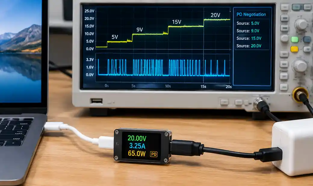 USB Power Delivery voltage and current negotiation between source and sink devices
Modern USB-C controllers implement the complete PD state machine including source capabilities advertisement, request negotiation, hard reset handling, and VBUS transition management. Texas Instruments controllers support all PD 3.1 profiles with integrated power path switching.
Key Technical Features
CC Logic and Configuration
Configuration Channel pins (CC1 and CC2) perform critical functions in USB-C operation. These pins handle cable plug detection, cable orientation sensing, legacy adapter detection, and power delivery communication. According to USB-C pinout specifications, CC pins use resistor coding to establish port roles.
Downstream Facing Ports (DFP/host) apply pull-up resistors (Rp) on CC pins while Upstream Facing Ports (UFP/device) apply pull-down resistors (Rd). Dual-Role Power (DRP) ports alternate between pull-up and pull-down to support both host and device operation. The controller measures CC pin voltage to determine cable attachment, orientation, and the connected device's current capability.
| CC Configuration | Resistor Value | Current Capability | Application |
|---|---|---|---|
| Default USB | Rp 56kΩ | 500mA - 900mA | Low-power peripherals |
| 1.5A @ 5V | Rp 22kΩ | 1.5A | Smartphones, tablets |
| 3.0A @ 5V | Rp 10kΩ | 3A | Laptops, high-power devices |
| PD Negotiation | BMC signaling | 5A maximum | Power Delivery devices |
CC pins also carry the Biphase Mark Coded (BMC) signaling for PD communication at 300 kHz. The controller's CC logic must decode BMC messages, validate CRC checksums, and respond within protocol timing requirements.
VBUS Control and Power Path
VBUS management determines power delivery reliability and safety. Modern controllers integrate power path switches or gate drivers that control external MOSFETs for VBUS switching. You should specify controllers with integrated discharge circuitry that safely removes VBUS voltage when cables disconnect.
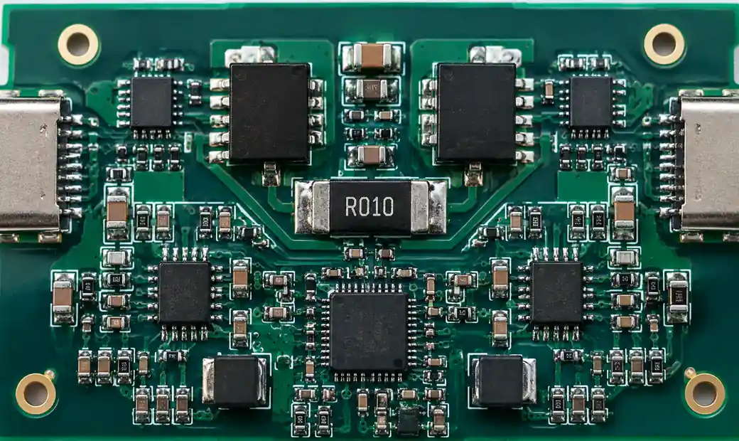 VBUS power path circuit with MOSFET switches and current sensing
The power path must handle inrush current when connecting high-capacitance loads. Controllers implement soft-start mechanisms that gradually ramp VBUS voltage to limit inrush current below cable ratings. According to USB-C PCB design guides, proper bulk capacitance management prevents false disconnect detection and voltage droop during load transients.
For EPR applications at 48V and 240W, VBUS control becomes more complex. The controller must coordinate multiple power stages, monitor current sharing, and implement rapid fault detection. Microchip's PD controllers support EPR with integrated high-voltage gate drivers.
Protection Features
Protection circuits prevent damage from electrical faults and user errors. Texas Instruments patents describe integrated VBUS-to-CC short protection that detects shorts between VBUS (potentially 48V at 5A) and signal pins.
Critical protection features include:
- Overvoltage Protection (OVP): Monitors VBUS and disconnects power if voltage exceeds safe limits (typically 22V for SPR, 52V for EPR)
- Overcurrent Protection (OCP): Limits current below cable and connector ratings using current sensing and fast gate control
- Reverse Current Protection: Prevents current backflow when VBUS voltage drops or during role swaps
- VBUS Discharge: Actively discharges VBUS capacitance to below 5V within 650ms per USB-C specifications
- ESD Protection: Built-in electrostatic discharge protection rated to IEC 61000-4-2 contact discharge levels (±8kV)
- Thermal Shutdown: Disables power path if junction temperature exceeds safe limits
The TPD4S311 protection IC combines 20V VBUS short-circuit protection, CC pin OVP, and IEC ESD protection in a single device for applications requiring enhanced protection beyond controller integration.
USB Type-C Controller Types
Controllers vary in integration level, power capability, and feature sets. You can select standalone PD controllers, integrated MCU-based solutions, or port controllers with data switching.
Standalone PD Controllers handle power delivery protocol and CC logic without data path management. These ICs communicate with a system microcontroller via I2C or GPIO interfaces. Diodes AP33772S provides PD control with I2C interface for voltage and current configuration.
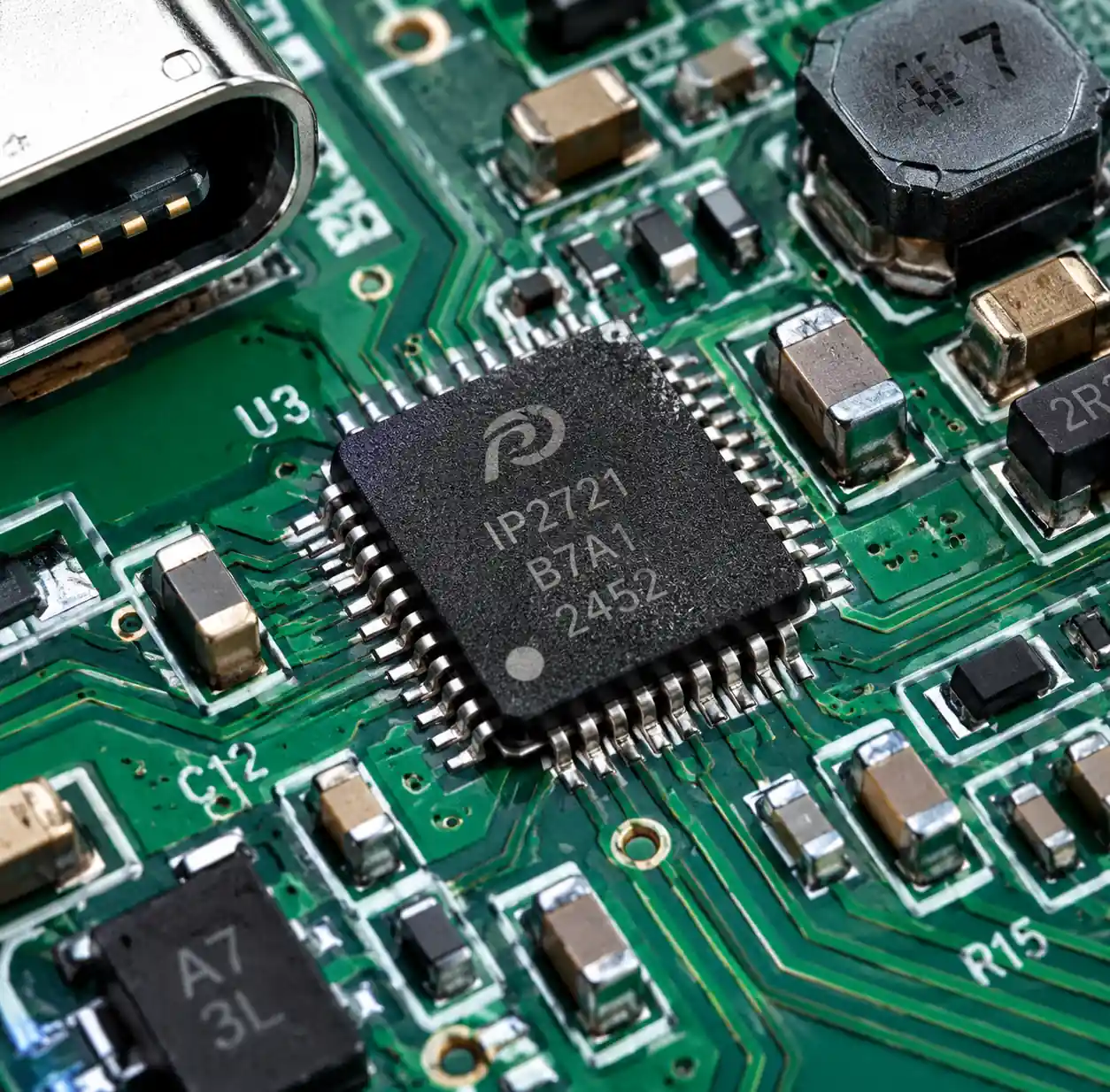 Standalone USB PD controller IC with I2C interface pins
MCU-Integrated Controllers combine a microcontroller core with PD hardware. Infineon EZ-PD CCG3PA features a 32-bit ARM Cortex-M0 with 64KB flash and 8KB SRAM for custom firmware development. These controllers support PD 3.1 SPR, PPS, and Quick Charge protocols with programmable state machines.
Port Controllers with Data Switching integrate USB data path multiplexing, SS signal conditioning, and PD control. These controllers manage USB 2.0 and SuperSpeed signal routing based on cable orientation and alternate mode entry.
| Controller Type | Power Capability | Data Support | Interface | Typical Applications |
|---|---|---|---|---|
| Standalone PD | Up to 240W | None | I2C, GPIO | Chargers, power adapters |
| MCU-Integrated | Up to 100W | Optional USB 2.0 | Programmable | Docks, hubs, custom devices |
| Port Controller | Up to 100W | USB 2.0 + SS | Integrated mux | Laptops, tablets, monitors |
| Hub Controller | Per-port PD | USB 3.x hub | Integrated hub | Multi-port hubs, docks |
Alternate Modes Support
USB Type-C alternate modes repurpose high-speed differential pairs for non-USB protocols. DisplayPort Alt Mode and Thunderbolt represent the most common alternate modes in commercial products.
DisplayPort Alt Mode reassigns SuperSpeed lanes to carry native DisplayPort signals. According to BenQ's technical explanation, this provides GPU-direct video output with zero lag, identical to native DisplayPort performance. Controllers supporting DP Alt Mode must implement the DisplayPort Alternate Mode on USB Type-C Standard.
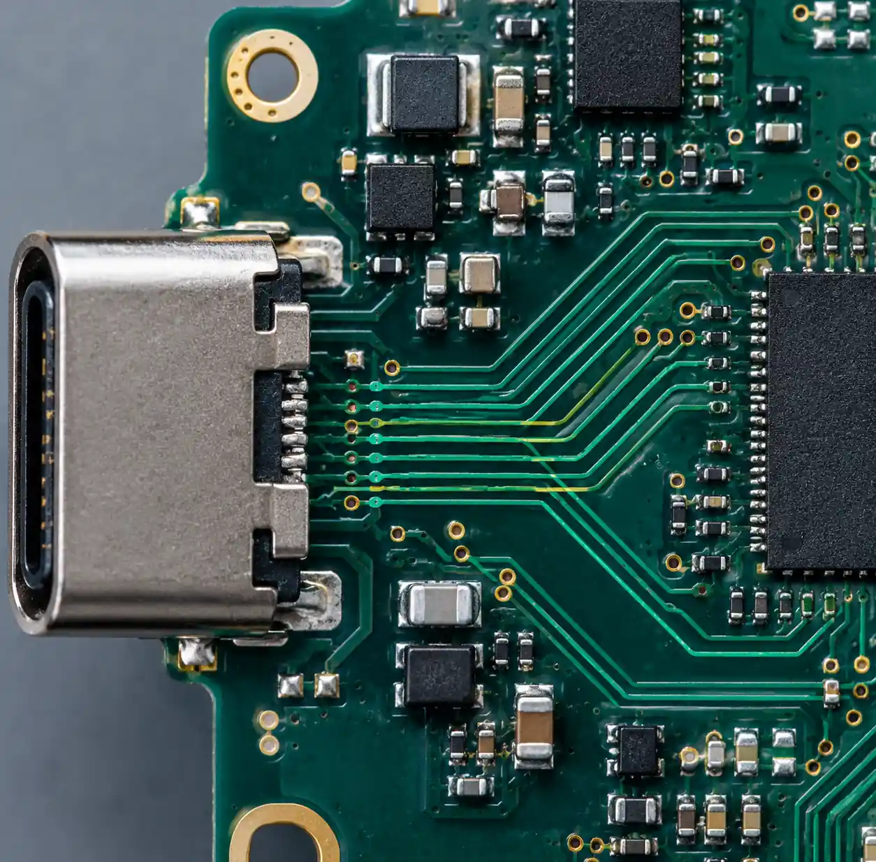 USB-C DisplayPort alternate mode lane configuration and signal routing
The controller negotiates with the sink device to determine lane configuration. Common configurations include:
- DP 2-Lane Mode: Two SuperSpeed lanes for DisplayPort, two lanes for USB 3.x data
- DP 4-Lane Mode: All four SuperSpeed lanes for DisplayPort, USB 2.0 only for data
Thunderbolt 3/4 Support requires controllers implementing Intel's Thunderbolt protocol. TESmart's KVM interface guide explains that Thunderbolt encapsulates PCIe, DisplayPort, and USB into a single 40Gbps stream. This enables external GPU connections, high-speed storage, and complex docking scenarios beyond DisplayPort Alt Mode capabilities.
Thunderbolt controllers mandate DisplayPort Alt Mode support but add PCIe tunneling capability. Of the 40Gbps bandwidth, up to 32Gbps can be allocated for PCIe data (PCIe 3.0 x4 equivalent). You should specify Thunderbolt controllers when applications require PCIe device connectivity or when targeting premium laptop and workstation markets.
USB4 Integration
USB4 specification unifies USB 3.2, USB PD, and Thunderbolt 3 into a single standard. USB4 controllers must support 40Gbps bidirectional data, USB PD 3.0 minimum, and Thunderbolt 3 compatibility.
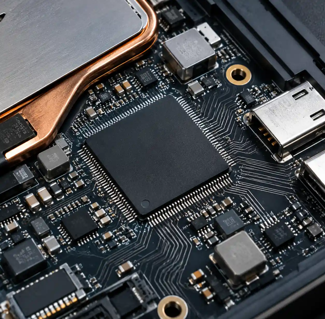 USB4 controller IC with Thunderbolt protocol support and PCIe tunneling
USB4 brings several architectural improvements:
- Tunneling Protocol: Encapsulates USB 3.2, DisplayPort, and PCIe traffic into dynamically allocated tunnels
- Dual-Lane Operation: Uses all four SuperSpeed differential pairs for symmetric 40Gbps operation
- Enhanced Power: Supports USB PD 3.1 EPR for up to 240W power delivery
- Backward Compatibility: Operates with USB 2.0, USB 3.2, and Thunderbolt 3 devices
Controllers implementing USB4 must include a router function that manages tunnel establishment, bandwidth allocation, and protocol conversion. The complexity of USB4 routers typically restricts these controllers to laptop, desktop, and premium dock applications.
For industrial and embedded applications not requiring 40Gbps data rates, USB 3.2 controllers with PD 3.1 support provide simpler implementation and lower cost. You should evaluate whether your application benefits from USB4 features before committing to the higher controller cost and design complexity.
Controller IC Comparison
Major semiconductor manufacturers offer USB-C controller ICs with varying capabilities and integration levels.
| Manufacturer | Controller Family | Power Support | Data Support | Alternate Modes | Key Features |
|---|---|---|---|---|---|
| Texas Instruments | TPS65988 | Up to 100W SPR | USB 2.0 + SS | DP, TB3 | Integrated power path, I2C interface |
| Infineon | EZ-PD CCG3PA | Up to 100W PD 3.1 | Optional USB 2.0 | DP | ARM Cortex-M0, 64KB flash |
| STMicroelectronics | STUSB4500 | Up to 100W | None (PD only) | None | Standalone sink controller, NVM config |
| Microchip | UPD350 | Up to 240W EPR | USB 2.0 | DP | EPR support, integrated gate drivers |
| ON Semiconductor | FUSB302 | Up to 100W | None (PD only) | None | Low-cost PD transceiver, I2C control |
| Diodes Inc. | AP33772S | Up to 100W | None (PD only) | None | I2C programmable, voltage selection |
Texas Instruments TPS65988 integrates power path switching for up to 100W, supports USB 2.0 and SuperSpeed data, and implements DisplayPort and Thunderbolt 3 alternate modes. This controller requires minimal external components for complete Type-C port implementation.
STMicroelectronics STUSB4500 targets sink-only applications like laptop adapters and charging devices. The controller stores PD profiles in non-volatile memory for autonomous operation without microcontroller intervention.
Selection Criteria
Choosing the appropriate USB-C controller requires evaluating power requirements, data needs, alternate mode support, and system integration.
Power Requirements Analysis:
- Determine maximum power delivery: <27W for phones/tablets, 27-100W for laptops, >100W for workstations
- Specify voltage profiles needed: 5V only, multiple fixed voltages, or PPS support
- Identify source/sink/dual-role operation requirements
Data and Alternate Mode Requirements:
- Assess data speed needs: USB 2.0 only, USB 3.2 Gen 1/2, or USB4
- Determine if DisplayPort output is required and at what resolution
- Evaluate if Thunderbolt connectivity justifies higher controller cost
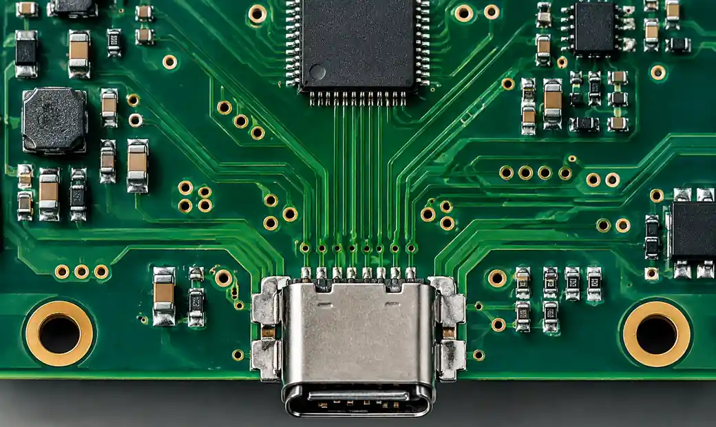 USB-C controller PCB layout showing impedance-controlled routing and component placement
Protection and Reliability:
- Specify OVP/OCP thresholds based on application environment
- Determine ESD immunity requirements (consumer vs industrial)
- Evaluate thermal management needs based on power levels and enclosure design
System Integration:
- Identify communication interface preference: I2C, SPI, or GPIO
- Assess available PCB space and package size constraints
- Determine if external power path components are acceptable or if integration is required
For cost-sensitive consumer products, standalone PD controllers with I2C interface provide basic functionality with low BOM cost. Industrial applications benefit from MCU-integrated controllers offering custom protocol support and diagnostic capabilities. Laptop and dock designs typically require full-featured port controllers with integrated data switching and alternate mode support.
Procurement Considerations
Sourcing USB-C controller ICs requires attention to supply chain factors, qualification standards, and regional compliance.
Lead Times and Availability:
USB-C controllers from major manufacturers typically have 12-16 week lead times for volume orders. According to supply chain data, automotive-qualified variants extend to 20-24 weeks due to additional testing requirements. You should plan buffer stock for critical production programs.
Component Authentication:
The market contains counterfeit USB-C controllers, particularly for premium devices. Work with authorized distributors to ensure authentic components. Verify marking codes, package dimensions, and perform basic electrical tests on incoming components.
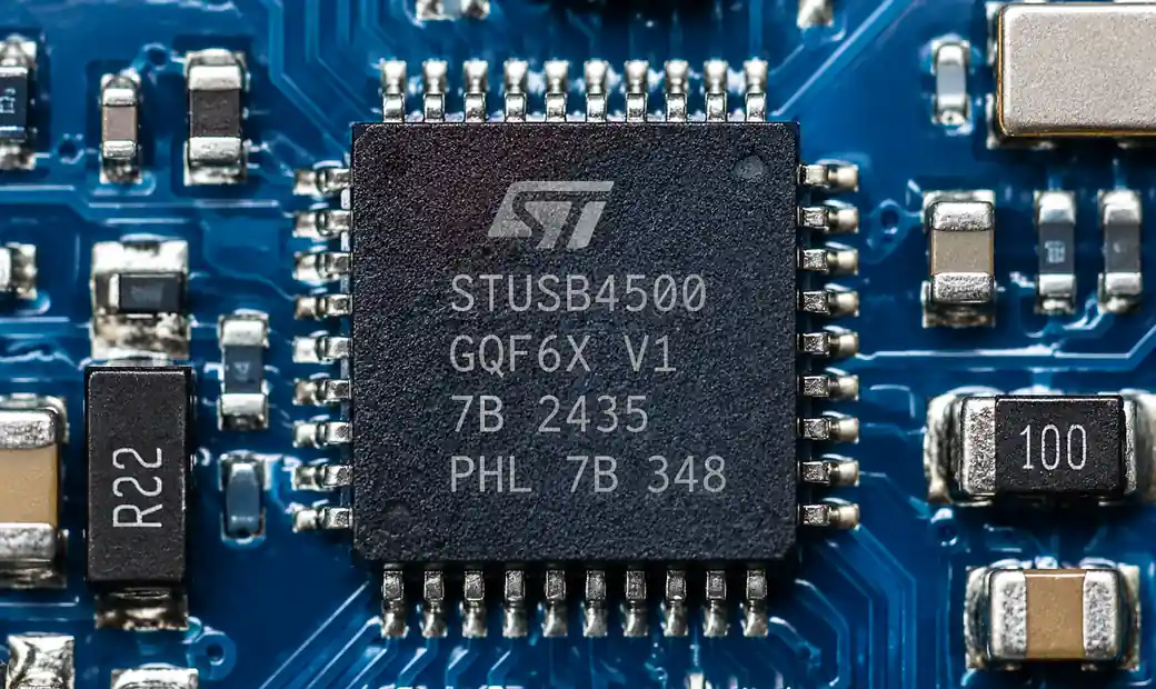 Authentic USB-C controller IC marking codes and package verification
Regional Compliance:
- RoHS/REACH: European market sales require RoHS 2011/65/EU and REACH compliance
- USB-IF Certification: Products bearing USB-C or USB PD logos require USB-IF compliance testing
- Regional Safety Standards: UL, CE, CCC marking depending on target markets
Cost Optimization:
USB-C controller prices range from $0.80 for basic standalone PD chips to $8.00 for fully integrated port controllers with Thunderbolt support. You can reduce total system cost by:
- Selecting controllers with integrated power path switches to eliminate external MOSFETs
- Choosing appropriate integration level—avoid paying for unused features
- Consolidating suppliers to achieve volume pricing across multiple controller families
- Considering second-source options for critical controllers
If you need reliable USB-C controller procurement for your electronics manufacturing, Hitop Tech offers comprehensive component sourcing services with global authorized distributor network. Our supply chain specialists serve customers in Africa and Southeast Asia with regional expertise for cost optimization and on-time delivery.
Contact us for USB-C controller sourcing and supply chain support.
Conclusion
USB Type-C controller and Power Delivery IC selection requires evaluating power specifications, data requirements, alternate mode support, and protection features. Modern controllers support USB PD 3.1 with up to 240W EPR capability, USB4 data speeds, and DisplayPort or Thunderbolt alternate modes. The right controller choice depends on your application power level, whether data connectivity is required, and the system integration constraints.
For reliable USB-C component procurement with authentic parts and competitive pricing, Hitop Tech provides global sourcing capabilities backed by authorized distributor relationships across Asia, Europe, and North America.
FAQ
What is the difference between USB PD 3.0 and PD 3.1?
USB PD 3.0 supports Standard Power Range up to 100W (20V/5A maximum), while USB PD 3.1 adds Extended Power Range profiles enabling up to 240W (48V/5A). PD 3.1 also refines PPS implementation for better fast-charging support.
Do all USB-C ports support Power Delivery?
No. USB-C defines the physical connector, but Power Delivery is optional. Some USB-C ports only support 5V charging or USB 2.0 data without PD negotiation. Check the controller datasheet to verify PD support.
What protection features are essential in USB-C controllers?
Critical protections include VBUS overvoltage protection (OVP), overcurrent protection (OCP), VBUS-to-CC short protection, ESD immunity, and thermal shutdown. Industrial applications should specify controllers with integrated protection rather than relying solely on external circuits.
Can I use a USB PD 2.0 controller for new designs in 2026?
USB PD 2.0 remains functional but limits power to 100W and lacks PPS support important for optimized battery charging. For designs with 5+ year lifespan, specify PD 3.1 controllers to support future devices and EPR requirements.
How do I select between standalone and integrated USB-C controllers?
Use standalone PD controllers for power-only applications like chargers. Choose MCU-integrated controllers when custom protocols or advanced diagnostics are needed. Specify port controllers with data switching for devices handling USB data and alternate modes.
What lead times should I expect for USB-C controllers?
Standard commercial controllers require 12-16 weeks for volume orders from authorized distributors. Automotive-qualified variants extend to 20-24 weeks. Plan buffer stock for production continuity and work with distributors offering supply chain optimization services.