Power over Ethernet (PoE): Complete Selection and Design Guide for Network Engineers
Power over Ethernet (PoE) technology has revolutionized network infrastructure by enabling simultaneous power and data delivery over standard Ethernet cables. This guide provides network engineers, system integrators, and facility managers with the technical framework needed to select, design, and deploy PoE systems effectively across various applications.
Table of Contents
- What is Power over Ethernet and Why It Matters
- Key IEEE Standards and Technical Specifications
- How to Select the Right PoE Standard for Your Application
- Technical Parameters and Performance Comparison
- Design Considerations and Common Implementation Pitfalls
- Supply Chain and Sourcing Considerations
- FAQ
- Conclusion and Next Steps
1. What is Power over Ethernet and Why It Matters
Power over Ethernet is a standardized technology that allows network cables to carry electrical power alongside data transmission. Instead of requiring separate power adapters and electrical outlets, PoE-enabled devices receive both connectivity and power through a single Cat5e, Cat6, or higher-grade Ethernet cable.
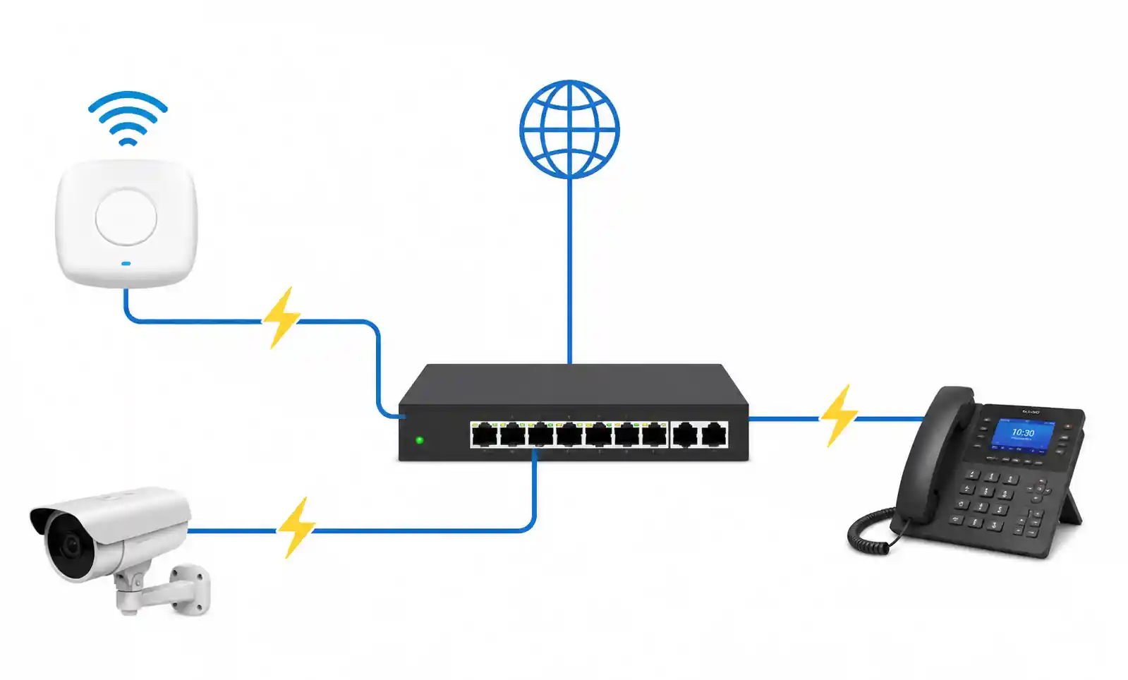
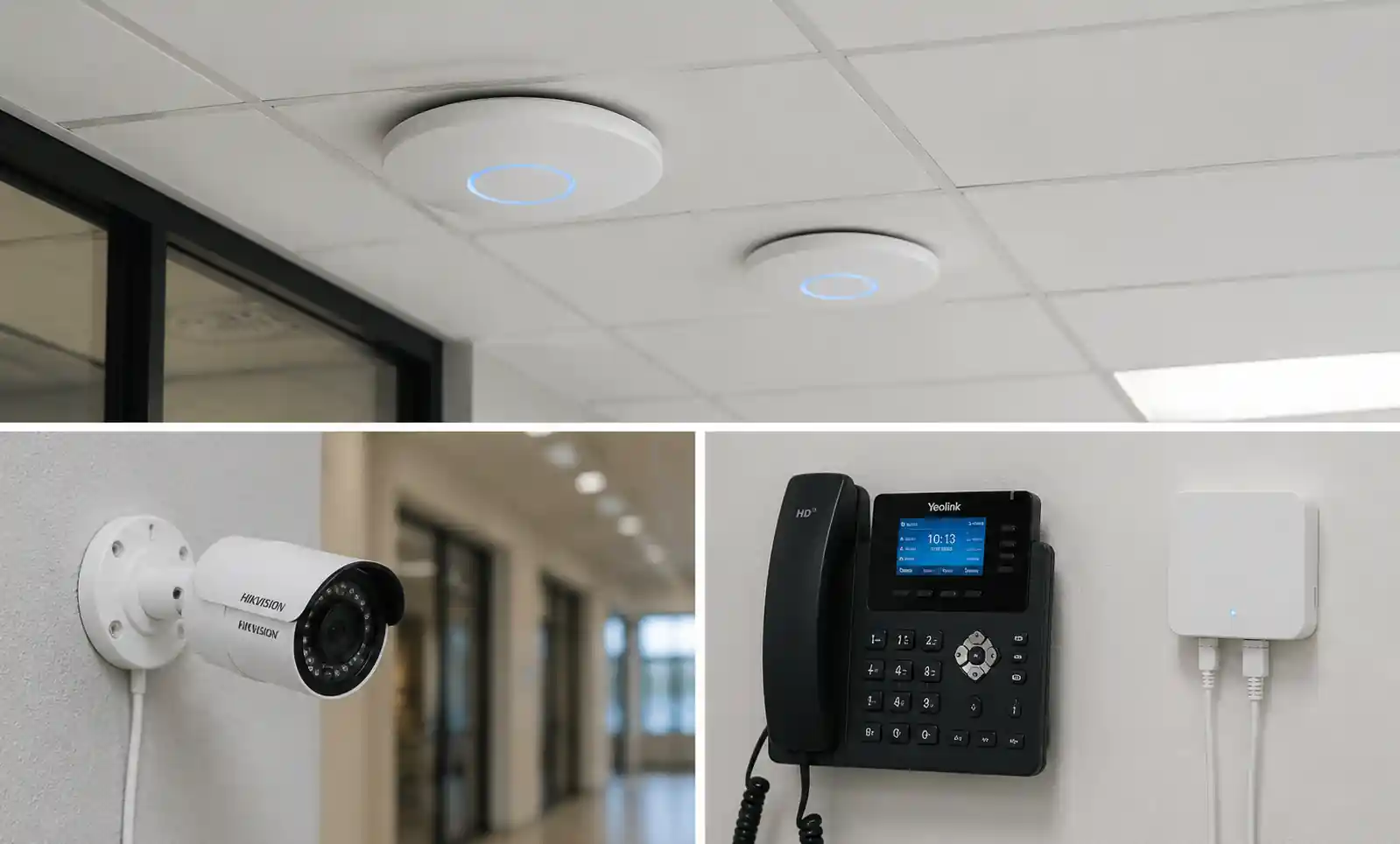
This technology fundamentally changes network architecture planning. In practical deployments, PoE eliminates the constraint of placing powered devices near electrical outlets, reduces installation costs by 30-50% compared to traditional wiring, and enables centralized power management through network switches. For facilities without nearby AC power access—such as ceiling-mounted access points, outdoor surveillance cameras, or remote IoT sensors—PoE often represents the only economically viable power delivery method.
The engineering value of PoE extends beyond convenience. Centralized power sourcing equipment (PSE) enables unified backup power through UPS systems, provides remote power cycling for troubleshooting, and simplifies compliance with building electrical codes. As network-connected devices proliferate across enterprise, industrial, and smart building environments, understanding PoE's technical capabilities and limitations becomes essential for system architects and integration teams.
2. Key IEEE Standards and Technical Specifications
The IEEE has established three primary PoE standards, each addressing different power requirements and application scenarios. Understanding these specifications is critical for matching PSE and powered device (PD) capabilities.
IEEE 802.3af (PoE)
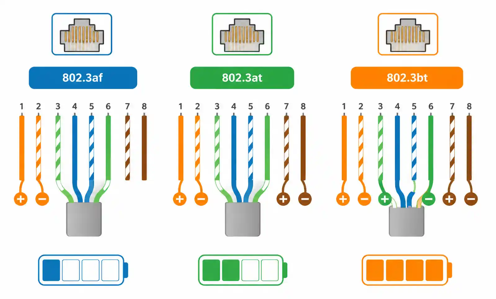
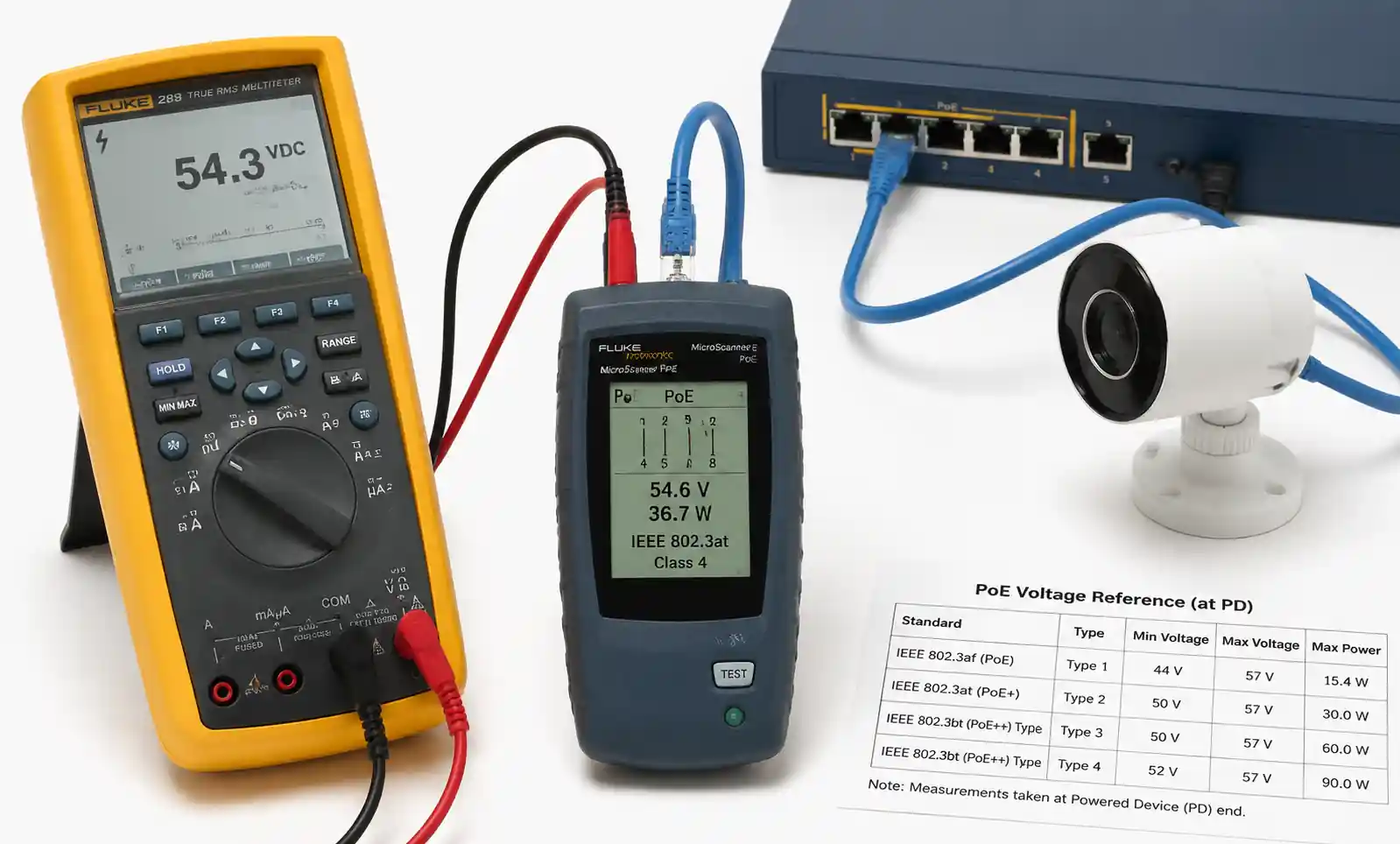
Ratified in 2003, 802.3af was the first standardized PoE specification. It delivers up to 15.4W at the power sourcing equipment, with 12.95W guaranteed at the powered device after accounting for cable resistance losses. The standard operates on two wire pairs (Mode A or Mode B) using DC voltages between 44-57V.
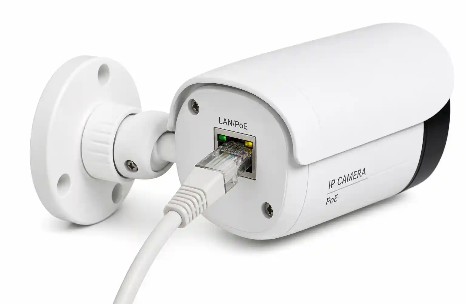
From a design perspective, 802.3af works well for basic VoIP phones, simple IP cameras without pan-tilt-zoom (PTZ), and low-power wireless access points. The key limitation is total power budget—devices requiring more than 13W at the endpoint cannot reliably operate under this standard, especially when using longer cable runs where resistive losses increase.
IEEE 802.3at (PoE+)
Released in 2009, 802.3at doubled the power delivery capacity to 30W at the PSE, providing 25.5W at the powered device. Like 802.3af, it uses two pairs but with higher current capacity. The standard maintains backward compatibility, allowing 802.3at PSE to power 802.3af devices safely.
This standard became the workhorse for enterprise networks. It supports PTZ cameras with heaters, high-performance wireless access points (Wi-Fi 5 and early Wi-Fi 6), video conferencing endpoints, and thin clients. When designing with 802.3at, verify the PSE's per-port power budget—many switches provide 30W only on a subset of ports, not across all ports simultaneously.
IEEE 802.3bt (PoE++ or 4PPoE)
Ratified in 2018, 802.3bt represents a significant architectural advancement. It defines two power classes: Type 3 (up to 60W at PSE, 51W at PD) and Type 4 (up to 90W at PSE, 71W at PD). Unlike previous standards, 802.3bt utilizes all four wire pairs for power delivery, doubling the current-carrying capacity without exceeding cable thermal limits.
The engineering implications are substantial. Type 3 enables LED lighting systems, building automation controllers, and high-power Wi-Fi 6E access points. Type 4 supports laptop charging, digital signage displays, small thin clients, and even low-power edge compute devices. However, 802.3bt requires Cat5e or better cabling in good condition—degraded cables or improper terminations can cause power delivery failures or thermal issues.
3. How to Select the Right PoE Standard for Your Application
Selecting the appropriate PoE standard requires balancing power requirements, cable infrastructure, cost, and future scalability. This methodology provides a systematic approach to PoE specification.
Step 1: Calculate Powered Device Requirements
Begin with the PD's maximum power consumption, not its average. Check the manufacturer's datasheet for peak power draw under full operational load. For example, a PTZ camera may consume 8W at rest but spike to 18W during simultaneous pan, zoom, and infrared illumination. Add a 15-20% safety margin to account for voltage drops and transient loads.
Step 2: Assess Cable Infrastructure and Distance
PoE power delivery degrades with distance due to copper resistance. At 100 meters (the IEEE limit for data transmission), voltage drop can reduce delivered power by 10-15% depending on cable gauge and quality. For longer runs or marginal cable plants, consider:
- Upgrading to Cat6 or Cat6a cable (lower resistance)
- Using PoE extenders or midspan injectors
- Reducing cable run length through network topology redesign
- Selecting a higher power class to compensate for losses
Step 3: Evaluate Environmental and Operational Factors
Temperature affects both PSE and PD operation. Outdoor deployments with extreme temperature swings may require devices with extended operating ranges (-40°C to +75°C). In these scenarios, verify that both the PSE and PD support the required temperature specifications, and account for additional power draw from heating or cooling mechanisms.
Step 4: Consider Power Budget at the Switch Level
PSE switches have both per-port and total chassis power budgets. A 24-port switch rated for 802.3at may provide 30W per port but have a total power budget of only 370W—insufficient to power all ports at maximum simultaneously. Calculate total connected load and verify it remains below 80% of the PSE's rated capacity to allow headroom for expansion.
Step 5: Plan for Future Requirements
Network infrastructure typically has a 5-7 year lifecycle. When selecting PoE standards today, consider emerging device requirements. Wi-Fi 7 access points will likely require 30-60W, and building IoT systems continue to add power-hungry sensors and controllers. Deploying 802.3bt-capable infrastructure now, even if current devices don't require it, can defer costly upgrade cycles.
4. Technical Parameters and Performance Comparison
Comparing PoE standards requires understanding multiple technical dimensions beyond raw power delivery. The following tables provide decision-making frameworks for different deployment scenarios.
PoE Standards Technical Comparison
| Parameter | IEEE 802.3af | IEEE 802.3at | IEEE 802.3bt Type 3 | IEEE 802.3bt Type 4 |
|---|---|---|---|---|
| PSE Power Output | 15.4W | 30W | 60W | 90W |
| PD Power Available | 12.95W | 25.5W | 51W | 71W |
| Voltage Range | 44-57V DC | 50-57V DC | 50-57V DC | 52-57V DC |
| Wire Pairs Used | 2 | 2 | 4 | 4 |
| Maximum Current | 350mA | 600mA | 600mA per pair | 960mA per pair |
| Detection Method | Resistive | Resistive | Enhanced classification | Enhanced classification |
| Backward Compatible | N/A | Yes (802.3af) | Yes (802.3af/at) | Yes (all previous) |
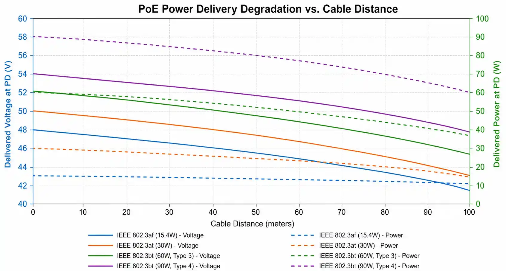
This table reveals critical design constraints. The jump from 802.3at to 802.3bt Type 3 isn't merely a power increase—it requires utilizing all four pairs, which changes fault tolerance characteristics. If one pair fails in a two-pair system, the device loses power entirely. In a four-pair system, the device may continue operating at reduced power, depending on implementation.
Application-Based PoE Selection Matrix
| Application Type | Typical Power Draw | Recommended Standard | Design Notes |
|---|---|---|---|
| VoIP Phone (Basic) | 4-7W | 802.3af | Any PoE standard works; optimize for cost |
| IP Camera (Fixed) | 6-12W | 802.3af | Consider 802.3at for night vision + heaters |
| IP Camera (PTZ + IR) | 15-25W | 802.3at | Account for motor draw during movement |
| Wireless AP (Wi-Fi 5) | 12-20W | 802.3at | Check manufacturer specs for 4x4 MIMO variants |
| Wireless AP (Wi-Fi 6/6E) | 25-40W | 802.3bt Type 3 | Higher-end models may need Type 3 |
| Digital Signage | 35-65W | 802.3bt Type 3/4 | Screen size dictates Type 3 vs Type 4 |
| LED Lighting Fixture | 15-50W | 802.3at to Type 3 | Varies greatly by lumens and efficiency |
| Building Automation | 10-30W | 802.3at | Controllers with multiple sensors may need more |
| Thin Client / Zero Client | 30-60W | 802.3bt Type 3/4 | Depends on processing requirements |
When reviewing this matrix, note that power requirements trend upward over product generations. A wireless access point from 2020 might operate on 802.3at, while its 2024 replacement with additional radios and processing power requires 802.3bt. This progression makes future-proofing through higher-capability PSE infrastructure a sound engineering investment.
The relationship between distance and power delivery requires special attention. At maximum cable length (100m) with Cat5e cable, the power loss can reach 12-15% due to conductor resistance. For example, an 802.3at PSE delivering 30W at the source may only provide 25.5-26W at the PD end. When operating devices near their maximum power threshold, this loss can cause brownout conditions or unreliable operation.
5. Design Considerations and Common Implementation Pitfalls
Successful PoE deployment requires attention to electrical, thermal, and compatibility factors that aren't immediately obvious from datasheet specifications.
Cable Quality and Termination Standards
PoE magnifies the consequences of poor cable installation. Unlike data-only Ethernet, which can tolerate marginal connections through error correction, PoE delivers continuous DC current that generates heat at high-resistance termination points. Improperly crimped connectors, untwisted pairs beyond specification limits, or kinked cables create hotspots that degrade performance or cause failures.
In 802.3bt deployments using all four pairs, cable quality becomes even more critical. A cable with one damaged pair might pass a basic data continuity test but fail under full power load. Insist on certified cable plant installations and perform both data certification (for insertion loss, return loss, NEXT, and FEXT) and DC resistance testing before commissioning PoE systems.
Power Negotiation and Classification
PoE devices negotiate power delivery through a classification protocol. The PSE first applies a low-voltage signature to detect if a valid PD is connected, preventing damage to non-PoE devices accidentally plugged into powered ports. After detection, the PD identifies its power class through a classification signature.
A common mistake is assuming that connecting an 802.3af device to an 802.3bt PSE automatically provides more power. The PD must request the higher power class during negotiation. Legacy devices incapable of LLDP-based power negotiation (required for 802.3bt) will only receive 802.3af or 802.3at power levels, even when connected to capable PSE. When planning upgrades, verify that existing devices support the power negotiation protocol of your target standard.
Thermal Management in Enclosed Spaces
Bundled cables carrying PoE generate more heat than non-powered cables. In conduit runs with multiple cables or ceiling plenums with poor airflow, this heat accumulation can approach cable temperature ratings, particularly with 802.3bt's higher power levels. The TIA/EIA-568 standard provides cable bundle derating guidelines, but these are often overlooked in PoE deployments.
For high-density PoE installations (such as access point or camera-intensive floors), conduct thermal analysis of cable pathways. Consider splitting bundles, using plenum-rated cable with higher temperature tolerance, or improving ventilation in enclosed spaces. PSE switches themselves also generate significantly more heat under full PoE load—ensure adequate rack cooling and follow manufacturer spacing recommendations.
Ground Loops and EMI Considerations
PoE systems can create ground loops when devices have multiple paths to earth ground (through both the Ethernet connection and other grounded interfaces like HDMI or USB). In industrial environments with significant electrical noise, these loops can induce interference or cause sporadic device resets.
Use isolation transformers at the PD for devices with multiple grounded connections. In outdoor installations, ensure proper surge protection and grounding architecture to prevent lightning-induced damage. IEEE 802.3bt devices must meet enhanced EMI requirements, but proper installation practices remain essential for reliable operation.
Compatibility Between PSE and PD Vendors
While PoE standards ensure basic interoperability, vendor-specific implementations sometimes create compatibility issues. Some older PSE implementations don't correctly handle the extended negotiation required by 802.3bt devices. Conversely, some PD devices implement non-standard power draw patterns that confuse PSE current monitoring circuits, causing port shutdowns.
Maintain a qualified vendor list based on interoperability testing. When deploying multi-vendor PoE ecosystems, conduct pilot testing with representative PSE and PD combinations before large-scale rollout. Document any discovered incompatibilities and their workarounds in your network design standards.
6. Supply Chain and Sourcing Considerations
PoE component availability and lead times significantly impact project timelines and total cost of ownership. Strategic sourcing requires understanding market dynamics and alternative solutions.
PSE Switch Selection and Availability
The market for PoE switches spans from unmanaged commodity devices to enterprise-grade managed switches with advanced power management. Enterprise switches from Cisco, Aruba, and Juniper typically carry premium pricing but include sophisticated power budgeting, per-port monitoring, and remote management capabilities essential for large deployments.
Lead times for enterprise switches have stabilized compared to 2021-2023 semiconductor shortages but remain longer than pre-pandemic norms. When specifying PSE infrastructure, balance between standardizing on a single switch model (for operational simplicity) and qualifying multiple vendors (for supply chain resilience). For critical deployments, consider dual sourcing or maintaining strategic spare inventory.
Component Obsolescence and Long-Term Support
PoE technology evolution creates obsolescence pressure. Some early 802.3af switches have reached end-of-life status, making replacement parts unavailable. When specifying new systems, verify that selected components have manufacturer commitment for at least 5-year availability and 10-year support lifecycles.
For specialized industrial or outdoor PoE components with extended operating temperature ranges, lead times can extend to 16-20 weeks. Plan these long-lead items into project schedules early. Distributors like Digi-Key, Mouser, and Newark maintain stock of common PoE components, but specialized items may require direct factory orders.
Cost Analysis: Per-Port Economics
Understanding the total cost of PoE delivery helps optimize system design. An 802.3af switch port might cost $30-50 in hardware, while 802.3bt Type 4 ports can reach $150-200. Multiply this across dozens or hundreds of ports, and the differential becomes significant.
For applications requiring only occasional high-power devices, consider hybrid architectures: deploy primarily 802.3at switching with targeted midspan injectors for devices needing 802.3bt. This approach optimizes capital expenditure while maintaining flexibility. However, factor in the operational complexity of managing midspan injectors—they represent additional failure points and complicate troubleshooting.
Certification and Standards Compliance
For applications requiring specific certifications (UL, CE, FCC, IEC), verify that selected PoE components carry appropriate marks. Industrial environments may require NEMA 4X enclosures for outdoor PSE. Medical facilities need IEC 60601-1 compliance. Government and defense applications might require TAA compliance or NDAA-compliant sourcing.
Certification requirements can significantly narrow vendor selection and extend lead times. Incorporate compliance verification into your sourcing checklist early in the design phase to avoid late-stage component substitutions that impact project schedules.
7. FAQ
What cable types support PoE, and can I use existing cabling?
PoE operates over Cat5e, Cat6, Cat6a, and Cat7 cables. Existing Cat5e installations can support 802.3af and 802.3at reliably. For 802.3bt, Cat5e works but Cat6 or better is recommended due to higher current draw and better thermal characteristics. The critical factor is cable condition—damaged or substandard cables that work adequately for data may fail under PoE load due to excessive resistance causing power loss and heat buildup.
How do I calculate the total power budget needed for a PoE switch?
Sum the maximum power draw of all connected devices (at the PD, not PSE output), add 20% for cable losses, then add another 20% growth margin. Verify this total against both the PSE's per-port and chassis-wide power budgets. For example, if you have 24 devices each requiring 20W at the PD, you need approximately 24 × 20W × 1.2 × 1.2 = 691W chassis power budget, which would require an 802.3at switch rated for at least 700W total power.
Can PoE damage non-PoE devices if accidentally connected?
No. IEEE PoE standards include mandatory safety mechanisms. Before delivering power, the PSE performs a signature detection test using low voltage (2.8-10V) to verify that a compliant PD is connected. Non-PoE devices won't present the correct signature resistance, so the PSE won't enable power on that port. This makes PoE safe for mixed environments where both powered and non-powered devices coexist.
What's the maximum distance for PoE?
The IEEE 802.3 standard specifies 100 meters (328 feet) for Ethernet data transmission, and PoE maintains this limit. However, actual reliable power delivery distance depends on cable gauge, power level, and acceptable voltage drop. For mission-critical applications or devices operating near their power threshold, consider limiting runs to 80-90 meters. PoE extenders can extend distance to 200 meters or more, but they introduce additional complexity and potential failure points.
How does PoE work with fiber optic networks?
PoE doesn't transmit over fiber since fiber cables don't conduct electricity. For fiber network segments requiring powered devices, use media converters with PoE output capability. These devices convert fiber to copper Ethernet while providing PoE on the copper side. Position the media converter within 100 meters of the powered device to stay within PoE distance limits.
What happens if a device requires more power than the PSE can deliver?
Properly designed systems handle this gracefully. During negotiation, if the PD requests more power than the PSE port can supply, the PSE either provides the maximum available power (if the PD accepts reduced-power operation) or doesn't enable power at all (if the PD requires full power). Some advanced PSE switches implement dynamic power management, temporarily reducing power to lower-priority devices when high-priority devices connect, based on administrator-defined policies.
Are there security concerns specific to PoE systems?
PoE itself doesn't introduce unique network security vulnerabilities—data security follows standard Ethernet protocols. However, the centralized power delivery creates operational security considerations. An attacker with physical access to PSE switches can disable all connected devices by removing power. This makes PSE infrastructure a critical asset requiring physical security controls. Additionally, some PSE switches allow remote power cycling via management interfaces, which should be protected with strong authentication and audit logging.
Can I mix different PoE standards on the same network?
Yes. PoE standards are backward compatible. An 802.3bt PSE safely powers 802.3at and 802.3af devices. However, legacy devices won't automatically consume more power just because higher-power PSE is available—they request power according to their design specification. When planning mixed deployments, map device power requirements to PSE capabilities carefully to avoid provisioning insufficient total power budget.
8. Conclusion and Next Steps
Power over Ethernet has gone from a nice-to-have to a must-have in network infrastructure. The evolution from 802.3af to 802.3bt Type 4 shows how power demands keep growing—now you can run things that used to need a wall outlet.
When picking PoE today, focus on three things: 1) real power needs now and in the future (don't forget peaks), 2) your cable quality—bad cabling kills PoE, and 3) total cost over time, not just upfront hardware.For new builds, spec 802.3bt even if you don't need it yet—retrofitting later costs way more. For existing setups with power shortages, audit your devices and try midspan injectors instead of swapping switches. And always test your cables and check thermal loads in dense racks—that's where most failures happen.
Need more? Check vendor app notes, IEEE specs, and do a pilot test with real gear before rolling out big. That catches nasty surprises early.