Reed Relay Selection Guide: Technical Parameters, Performance Comparison, and Design Considerations (2026)
Reed relays give you fast switching, true galvanic isolation, and hermetic sealing in one package. For precision measurement, ATE, and medical instrumentation, they're hard to beat. But you have to get the specs right—contact resistance, operate time, and coil drive all matter. Here's what engineers actually need to know before specifying one.
Table of Contents
- Key Technical Parameters
- How to Choose the Right Reed Relay
- Reed Relay vs Alternatives
- Selection by Application
- Design Considerations and Common Pitfalls
- Supply Chain and Sourcing
- FAQ
- Conclusion
Key Technical Parameters
Switching Voltage and Current: Ratings are interdependent. A 200V/0.5A relay can't safely switch 200V at 1A—it's about total power. Inductive loads generate voltage spikes 2-3× the supply, so derate or add suppression. Capacitive loads create inrush current that can weld contacts if it exceeds the make current rating.
Contact Resistance: Typically 50-200mΩ initial, rising to 500mΩ at end-of-life. In precision analog circuits, even 100mΩ creates offset errors (I × Rc). Resistance drifts with temperature and switching cycles. For critical applications, rhodium or ruthenium plating holds resistance stable longer than gold.
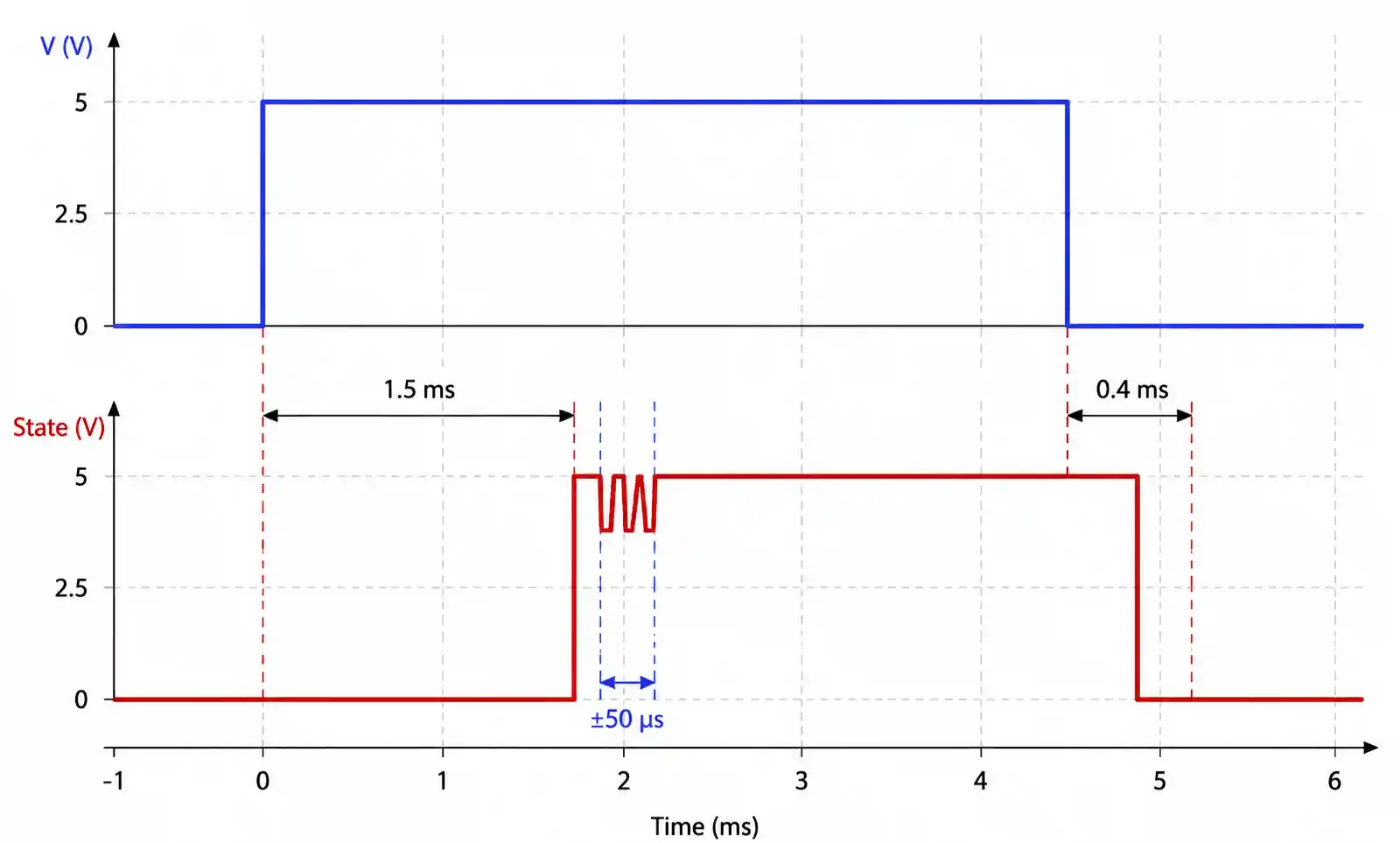
Operate and Release Time: Operate time runs 0.5-2ms; release time 0.2-0.5ms. Operate time varies ±20% unit-to-unit and increases at lower coil voltage. If you're building a switching matrix for ATE, timing skew between multiple relays matters.
Coil Power and Voltage: Coil consumption ranges 150-500mW. Low-power relays (<200mW) can run from logic-level drivers; higher power needs dedicated drivers. Most relays operate at 70-110% of nominal voltage, but operate time stretches at the low end.
Mechanical vs Electrical Life: Mechanical life is 100M-1B cycles with no load. Electrical life drops to 100K-10M cycles depending on load type. Inductive loads cut life by 10-100× compared to resistive at the same voltage/current. Always check the manufacturer's load-life curves.
How to Choose the Right Reed Relay
Start with load characteristics: DC or AC, resistive/inductive/capacitive, voltage, current, switching frequency.
For precision measurement (DMMs, data loggers), prioritize low contact resistance (<100mΩ) and low thermal EMF (<5µV). For high-voltage switching, focus on insulation resistance (>10¹⁰Ω) and dielectric withstand voltage. For high-speed applications, operate time and contact capacitance matter most.
Environmental factors: Standard relays run -40°C to +85°C; industrial grades go to +125°C. At high temperatures, coil resistance rises (reducing drive current) and contact resistance increases. For shock/vibration environments, look for reinforced package construction and specified contact bounce.
Reed Relay vs Alternatives
| Parameter | Reed Relay | Electromechanical Relay | Solid-State Relay (SSR) | MOSFET Switch |
|---|---|---|---|---|
| Switching Speed | 0.5-2ms | 5-15ms | 0.1-1ms (zero-cross) | <1µs |
| Mechanical Life | 100M-1B cycles | 100K-10M cycles | Unlimited | Unlimited |
| Electrical Life | 100K-10M cycles | 100K-1M cycles | Unlimited | Unlimited |
| Contact Resistance | 50-200mΩ | 10-100mΩ | 50-500mΩ | 10-500mΩ |
| Leakage Current (open) | <1pA | <1nA | 1-100µA | 10nA-10µA |
| Contact Isolation | >10¹²Ω | >10¹⁰Ω | 10⁶-10⁹Ω | 10⁹-10¹²Ω |
| Power Consumption | 150-500mW | 200-1000mW | Zero (control) | Zero (static) |
| Cost (relative) | Medium | Low | High | Low-Medium |
Reed relays sit between electromechanical and solid-state. They give you true isolation (no leakage) with faster switching than traditional relays. For low contact resistance and true galvanic isolation, they're often the only practical option.
Selection by Application
| Application | Switching Voltage | Switching Current | Contact Resistance Priority | Operate Time Priority | Key Criteria |
|---|---|---|---|---|---|
| Precision DMM/DAQ | 30-100V | 10-100mA | Critical (<100mΩ) | Moderate | Low thermal EMF, stable Rc |
| ATE Switching Matrix | 50-150V | 100mA-1A | Moderate | Critical (<1ms) | High cycle life, low coil power |
| High-Voltage Measurement | 200-300V | 10-50mA | Low | Low | High insulation resistance |
| RF Signal Routing | 10-50V | 10-100mA | Moderate | Critical (<0.5ms) | Low capacitance (<0.5pF) |
| Medical Device Isolation | 30-100V | 10-500mA | Moderate | Moderate | Medical certification, sealing |
| Industrial Control | 100-250V | 500mA-3A | Low | Moderate | Wide temp range, rugged |
Different applications demand different priorities. Precision measurement can't tolerate 100mΩ contact resistance—a 10µV offset at 100mA matters at microvolt levels. ATE systems switching thousands of connections per second need speed and cycle life above all. High-voltage applications care more about insulation and dielectric strength than contact resistance.
Design Considerations and Common Pitfalls
Coil Drive: Never drive a reed relay coil directly from a GPIO. Even 200mW relays draw 40-100mA at 5V—exceeding typical GPIO limits. Use a MOSFET or BJT switch. Include a flyback diode (1N4148) across the coil to clamp inductive kickback—without it, voltage spikes can hit 10-20× supply, destroying the driver.
Contact Protection: For inductive loads, suppression is mandatory. Use RC snubbers (0.1µF + 100Ω) across contacts or varistors for AC loads. Inductive kickback can exceed 1000V without protection. Capacitive loads need current limiting to prevent inrush welding—series resistance or pre-charge circuits. Check the relay's make current rating (typically 2-5× continuous).
PCB Layout: Maintain proper creepage/clearance. IEC 60664-1 requires 3mm for 300V working. Inadequate spacing causes arcing and breakdown. Separate coil return (noisy ground) from signal ground. Route coil traces away from sensitive analog signals to minimize EMI.
Timing: Account for operate time variation. Add guard time (2-3× max operate time) before sampling. For break-before-make switching, verify the relay guarantees dead time (typically 0.1-0.5ms). If your application can't tolerate momentary shorts, select a relay explicitly rated for BBM.
Supply Chain and Sourcing
Major manufacturers: Pickering Electronics, Coto Technology (Sensata), Standex Electronics, Meder Electronics, Littelfuse. Expect 8-16 week lead times for volume orders. Chinese alternatives (Huike, Coto China) offer 4-8 week lead times for commercial/industrial applications.
Lifecycle: Reed relay lifecycles typically run 10-15 years, but specific part numbers can go obsolete with 6-12 months notice. For products with >5 year support, design with widely available standard packages and maintain multi-source qualification.
Cost optimization: Pricing varies 5-10×. High-voltage (>200V), high-current (>1A), or fast (<1ms) models command premiums ($5-20+). Don't over-specify. Volume breaks at 100, 500, 1000, 5000 pieces. For >10K units/year, negotiate annual purchase agreements.
FAQ
What's the difference between Form A, Form B, and Form C reed relays?
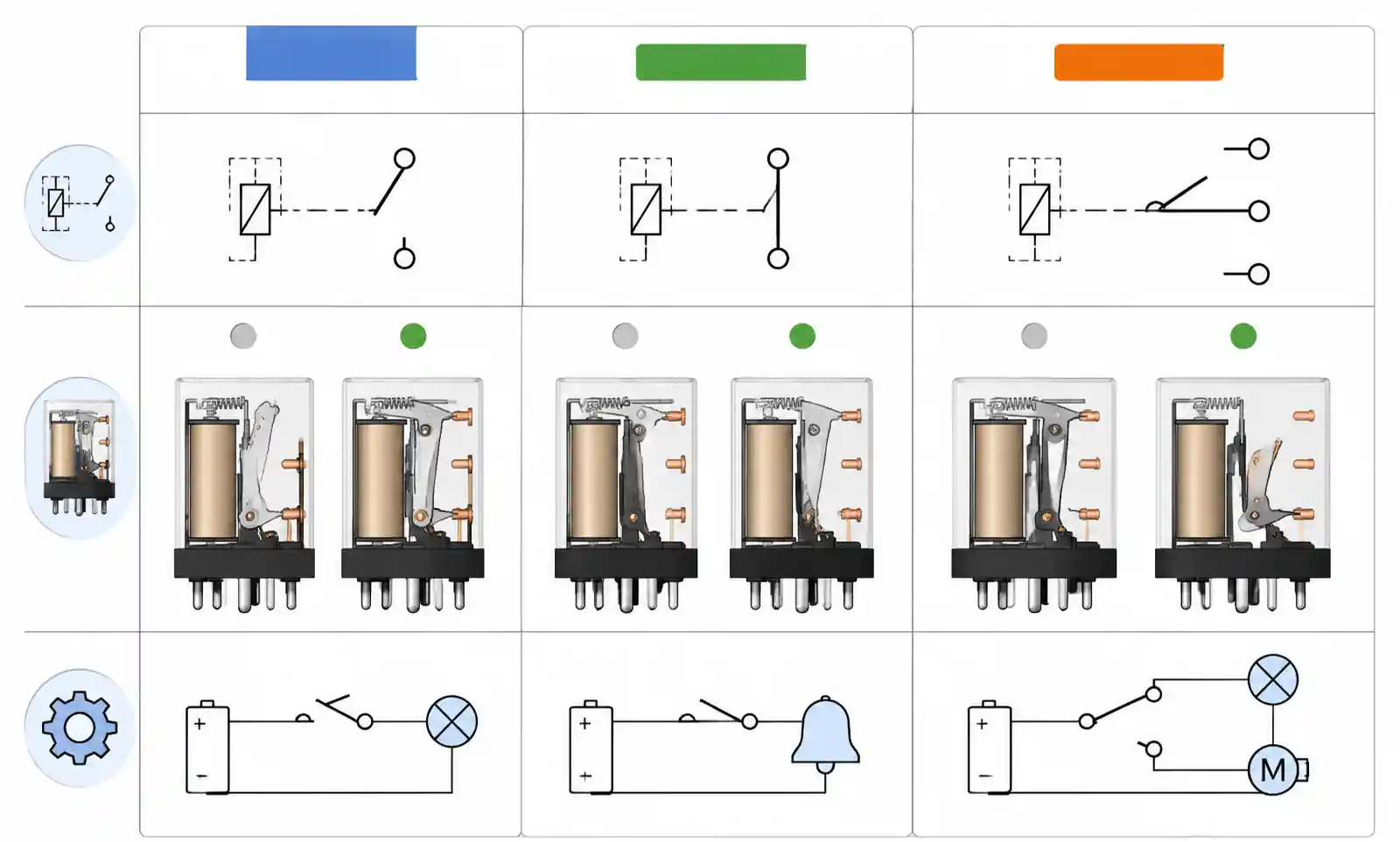
Form A (SPST-NO) closes when energized. Form B (SPST-NC) opens when energized. Form C (SPDT) has both NO and NC contacts with common terminal. Form A is most common (90% of applications). Form C is used for signal routing or when you need position feedback. Form B is rare because the default energized state wastes power.
Can I use a reed relay for AC switching?
Yes, but at reduced current. A 200V/1A DC relay might be limited to 120VAC/0.5A. AC switching causes more contact erosion due to arc energy. For AC power control, solid-state or electromechanical relays are better. Reed relays are best for low-voltage AC signal switching (<120VAC, <500mA).
How do I calculate the required contact rating?
Take max voltage and current, then add margin. Resistive DC loads: multiply max current by 1.5×. Inductive loads: multiply by 3× for back-EMF. Capacitive loads: measure inrush and verify it doesn't exceed the make current rating. Consult manufacturer load-life curves for your operating point.
What causes contact resistance to increase over time?
Micro-arcing creates insulating oxide layers. Mechanical wear flattens contact geometry. Rhodium and ruthenium plating hold resistance lower longer than gold. For critical applications, monitor periodically and replace when resistance exceeds 2× initial value or system tolerance.
Should I use latching or non-latching relays?
Non-latching needs continuous coil power. Latching maintains state without power, using brief pulses to change state. Use latching in battery-powered arrays where 50-200mW per relay adds up. Cost is 1.5-2× more but eliminates standby power. Tradeoff: added control complexity and no coil current to monitor for failure.
How do I handle ESD protection for reed relay contacts?
Add TVS diodes or varistors on contact terminals exposed to external connections. For coils, the flyback diode provides some protection, but add a bidirectional TVS if the coil is accessible outside the system. Follow IEC 61000-4-2 guidelines—adequate ground planes, keep relay terminals away from high-ESD areas.
Can I parallel reed relays for higher current?
Strongly discouraged. Contact resistance mismatch causes unequal current sharing—the lower-resistance relay carries more current, degrades faster, and eventually takes the full load. If you need higher current, use a single relay rated for the full load.
What's the expected lifetime in my application?
Depends on voltage, current, load type, and switching frequency. A relay rated 10M cycles at 30V/100mA resistive might only do 500K at 200V/1A. Inductive loads reduce life 10-100×. If manufacturer data isn't available, test a sample under accelerated conditions before committing to production.
Conclusion
Reed relays give you fast switching, isolation, and long mechanical life—essential for precision measurement, ATE, and instrumentation. Get the specs right: contact resistance for analog accuracy, operate time for speed, coil drive for reliability. Don't over-specify, but don't under-protect.
Before finalizing: verify critical parameters at worst-case conditions (temperature extremes, end-of-life contact resistance, minimum coil voltage). Request samples and test in your actual circuit. For production volumes, engage manufacturer FAEs early—they can spot cost reductions and design optimizations.