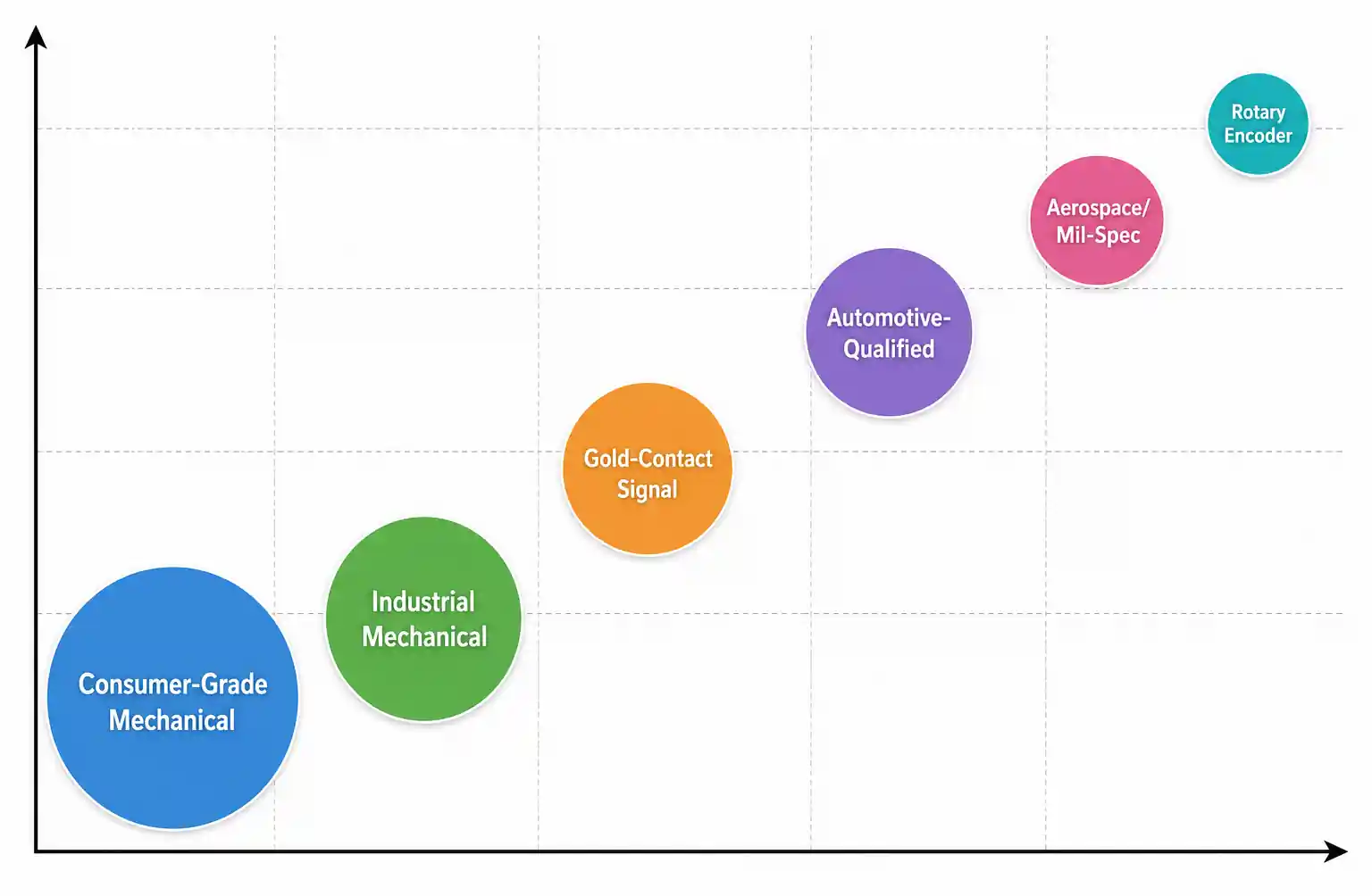
Rotary Switch Selection Guide: Technical Parameters and Design Considerations for Engineers (2026)
Rotary switches are everywhere—industrial panels, automotive dashboards, test equipment. Pick the wrong one and you'll chase intermittent failures or field returns. This guide covers the technical parameters that actually matter when specifying rotary switches, the trade-offs between mechanical selectors and encoders, and the design gotchas that show up six months into production.
Table of Contents
- Key Technical Parameters
- Rotary Switch Types and Technologies
- How to Choose the Right Rotary Switch
- Performance Comparison by Application
- Design Considerations and Common Pitfalls
- Supply Chain and Sourcing
- FAQ
- Conclusion
Key Technical Parameters
Contact Configuration (Poles and Throws): A "2P6T" switch controls two independent circuits, each selectable across six positions. Single-pole designs handle simple mode selection; multi-pole configurations switch multiple signals in sync. Check whether poles share common terminals—this affects crosstalk in sensitive analog circuits.
Current and Voltage Ratings: Datasheets list resistive, inductive, and capacitive ratings separately because loads behave differently. A switch rated 5A at 125VAC resistive might only handle 2A inductive. DC ratings are often much lower than AC—DC arcs don't self-extinguish. Always verify against worst-case load, including inrush. Capacitive loads like LED drivers can draw 10-20× steady-state current at startup.
Rotational Life: Specifies how many full rotation cycles the switch mechanism survives before wear degrades performance. Mechanical life and electrical life are different—a switch might claim 100,000 mechanical cycles but only 50,000 electrical cycles at rated load. For applications with frequent user interaction, mechanical life becomes the limiting factor.
Environmental Specs: IP ratings define dust and moisture protection. IP67 survives temporary immersion. Panel-mount switches generally achieve better IP ratings than PCB-mount types. Temperature range matters—automotive applications demand -40°C to +125°C. At temperature extremes, lubricants stiffen and plastic components warp.
Rotary Switch Types and Technologies
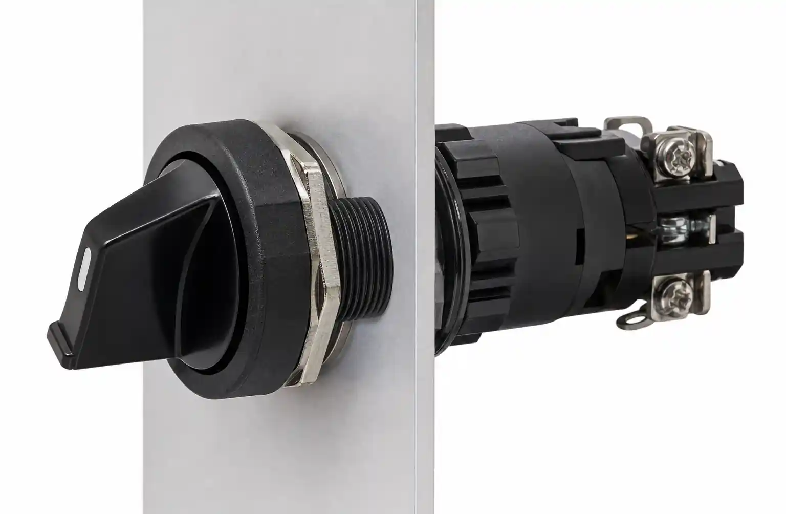
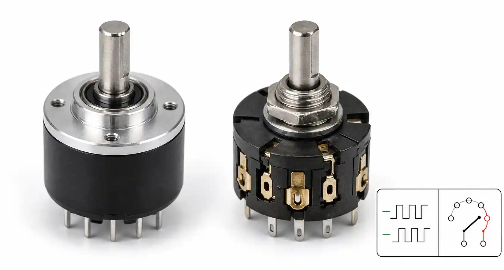
Mechanical Rotary Selectors: Physical contacts make and break circuits at discrete positions. Ideal for mode selection, input routing, and multi-way switching. Break-before-make (BBM) versus make-before-break (MBB) matters—BBM prevents brief shorts between adjacent positions; MBB ensures signal continuity but requires handling overlap. Audio and RF typically need BBM.
Rotary Encoders: Convert shaft rotation into pulses without discrete switching contacts. Incremental encoders output quadrature signals (A and B channels) indicating direction and speed. Absolute encoders output unique codes for each position—they remember position after power loss. Encoders eliminate contact bounce entirely, making them preferred for immediate, noise-free response.
| Technology | Position Detection | Unlimited Rotation | Requires Debounce | Typical Life | Best For |
|---|---|---|---|---|---|
| Mechanical Selector | Physical detents | No | Yes | 10K-100K cycles | Mode selection, direct load switching |
| Incremental Encoder | Optical/magnetic pulses | Yes | No | 1M+ cycles | Volume, tuning, digital input |
| Absolute Encoder | Unique position codes | No (360° coded) | No | 1M+ cycles | Robotic joints, position memory |
| Mechanical Encoder | Contact switching | Yes | Yes | 50K-200K cycles | Cost-sensitive digital input |
How to Choose the Right Rotary Switch
Step 1: Characterize the load. Voltage (AC/DC), steady-state current, load type (resistive/inductive/capacitive). For inductive loads, calculate or measure inrush and plan for external arc suppression (flyback diodes, snubbers). For signal-level circuits, contact resistance and material become primary concerns. Gold-plated contacts maintain <50mΩ resistance over life—silver tarnishes and creates intermittent connections at low currents.
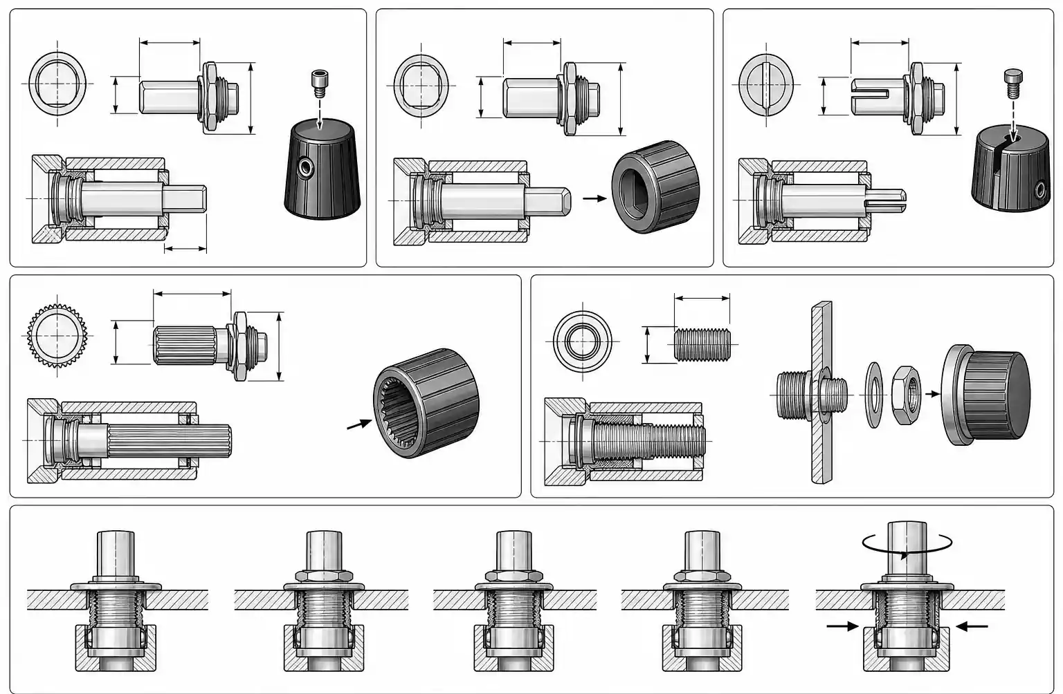
Step 2: Decide mounting and interface. PCB-mount simplifies assembly but exposes the switch to reflow temperatures and board flex. Panel-mount offers better sealing and field replacement but requires panel cutouts. Shaft configuration matters—slotted/D-shaft accepts set-screw knobs; knurled suits press-fit. Verify mounting orientation—some switches specify vertical mounting only.
Step 3: Map environmental exposure. Office equipment needs no specific IP rating (IP20 equivalent). Factory floor needs IP54 minimum. Outdoor or washdown requires IP65-IP67. Temperature rating must cover both operating and storage extremes. Consumer: 0°C to +70°C; industrial: -20°C to +85°C; automotive: -40°C to +125°C.
Step 4: Check application-specific features. Some switches integrate push-button function. Illuminated positions aid low-light operation. Coded outputs (BCD, Gray code) interface directly with digital systems. For audio/RF, specify >80dB port-to-port isolation and <10mΩ contact resistance variation between positions.
| Application | Key Requirements | Typical Specs | Watch For |
|---|---|---|---|
| Automotive Climate | -40°C to +125°C, 100K+ cycles, sealed | 6-12 position, panel mount, IP67 | Contact resistance drift vs temperature |
| Industrial HMI | High IP rating, robust detent, noise immunity | 2-6 position, 3-5A contact rating | EMI susceptibility—shielded cable if low-level signals |
| Audio Equipment | Low contact resistance (<30mΩ), >90dB isolation | Gold contacts, BBM | L/R balance matching between poles |
| Medical Device UI | 50K+ cycles, autoclavable (some), tactile feedback | Sealed encoder or gold selector | Cleaning agent compatibility |
| Test Equipment | Minimal bounce, stable contact resistance | Precision selector, PCB mount | Budget 20ms software debounce minimum |
Performance Comparison by Application
Different applications prioritize different parameters. Don't over-specify features you don't need—but don't under-specify critical ones.
| Feature Upgrade | Typical Cost Impact | When It's Worth It |
|---|---|---|
| Gold vs silver contacts | +40-80% | Signal-level applications (<100mV or <100µA) |
| IP67 vs IP40 sealing | +50-100% | Outdoor, washdown, food service environments |
| 100K vs 50K cycle life | +30-60% | High-frequency interaction, difficult replacement |
| Illuminated positions | +60-150% | Low-light operation, premium product differentiation |
| Encoder vs mechanical | +20-200% | Unlimited rotation, contact bounce unacceptable |
| AEC-Q or MIL-STD | +100-300% | Automotive production, contractually required |
Design Considerations and Common Pitfalls
Inadequate contact current for self-cleaning: Gold contacts need 10-100µA minimum switching current to break through oxide films. Silver needs 100µA-1mA. Designs switching sub-microamp signals will develop intermittent connections over time as oxidation builds up. If you're below minimum switching current, specify gold contacts and consider periodic "wetting current" pulses.
Ignoring load type in contact rating: Using resistive ratings for inductive or capacitive loads is a common failure. Inductive loads generate back-EMF that sustains arcing and welds contacts. Capacitive loads draw 10-20× inrush current at startup. Always specify against actual load type and add external arc suppression for inductive loads above 50mA.
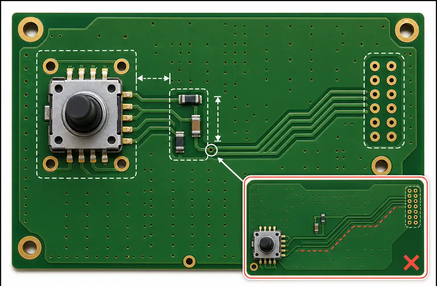
Poor PCB layout for contact bounce: Long traces between switch and debouncing circuits act as antennas, picking up noise that triggers false counts. Place debouncing components within 10mm of switch contacts. Add series resistance (1kΩ-10kΩ) immediately at the switch pin before routing.
Insufficient shaft support: Panel-mount switches are designed for front-panel force only—they're not structural members. Knobs larger than 30mm diameter or longer than 25mm need bushing support to prevent bearing wear inside the switch.
Seal integrity over thermal cycling: IP-rated switches rely on gasket compression. Thermal cycling relaxes compression over time. For outdoor applications exposed to daily thermal cycles, test at least 100 cycles (-20°C to +60°C) before production release.
Design verification checklist:
- [ ] Contact rating verified against worst-case load (including inrush)
- [ ] Load type matches datasheet test conditions
- [ ] Minimum switching current requirement met
- [ ] Debouncing implemented (hardware or software, 20ms minimum)
- [ ] IP rating matches worst-case environmental exposure
- [ ] Rotational life exceeds expected cycles by 3-5× margin
- [ ] Contact material appropriate for signal levels
- [ ] Break-before-make verified for your application
Supply Chain and Sourcing
Major manufacturers: Grayhill, C&K Switches, NKK Switches, Lorlin (top tier—extensive families, technical support, 8-16 week lead times). E-Switch, CTS, Apem (mid tier—good quality, moderate pricing, 6-12 week lead times). Various Chinese OEMs (low tier—attractive pricing, inconsistent quality, minimal support).
Lead times: Standard catalog switches from distributors ship 1-3 days for in-stock items. Specialized configurations—high IP ratings, gold contacts, multi-pole designs—run 12-16 weeks. Order samples 6+ months before production.
Cost optimization:
- Use standard catalog parts vs custom: saves 30-50%
- Qualify multiple sources: saves 15-25%
- Negotiate volume pricing at >5K units: saves 20-40%
- Optimize specs to broaden options: saves 25-40%
FAQ
What's the difference between rotary switches and rotary encoders?
Rotary switches have physical contacts that directly open and close circuits at discrete positions. They switch loads up to several amps with simple wiring. Rotary encoders convert shaft rotation into electrical pulses—they're sensors, not switches. They need downstream logic (microcontroller, PLC) to interpret position and control loads. If you need direct load control, use a mechanical switch. If you need unlimited rotation or software-configurable behavior, use an encoder.
How do I calculate the required contact current rating?
Start with steady-state current, then characterize load type. Resistive loads (heaters, incandescent lamps): use steady-state directly. Inductive loads (relays, motors, solenoids): inrush is 5-10× steady-state—select a switch rated for inrush or add external arc suppression. Capacitive loads (power supplies, LED drivers): measure inrush with oscilloscope—10-20× steady-state for the first few milliseconds. Always use the actual load type rating, not resistive, and include 2× margin.
Can rotary switches be used in automotive applications?
Yes, but only automotive-qualified parts. They require -40°C to +125°C operation, 100K+ cycles, sealed construction (IP67), and often AEC-Q200 qualification. Standard industrial or consumer switches won't survive. Expect 2-3× consumer pricing and 16-20 week lead times.
What are the key parameters in a rotary switch datasheet?
Contact configuration (poles/throws), current and voltage ratings by load type, rotational and electrical life, contact resistance (initial and over life), operating temperature range, IP rating, mounting style/dimensions, shaft type/dimensions, and detent strength. For signal applications, also check contact material (gold preferred), pole-to-pole isolation, and break-before-make vs make-before-break.
Do rotary switches need debouncing circuits?
Mechanical rotary switches absolutely need debouncing for digital interfaces. Contact bounce lasts 1-20ms, causing false reads or multiple counts. Implement hardware debouncing (RC filter + Schmitt trigger) or software debouncing (ignore transitions for 20ms). Rotary encoders (optical or magnetic) don't generate contact bounce and don't need debouncing.
What's the difference between break-before-make and make-before-break?
Break-before-make (BBM) opens the old connection before closing the new one—prevents short circuits between adjacent positions. Standard for audio, RF, and signal routing. Make-before-break (MBB) briefly connects both positions during transition—prevents open-circuit conditions. Used in motor control or power switching where open circuit is worse than a brief short. Most rotary switches default to BBM.
Why do some rotary switches have gold-plated contacts?
Gold prevents oxidation and maintains stable, low contact resistance over the switch lifetime. Critical for signal-level applications (<100mV or <100µA) where normal switching current isn't sufficient to break through oxide films on silver contacts. Gold contacts maintain <30-50mΩ over 50K+ cycles. Silver contacts drift to 100-200mΩ. Gold costs 40-80% more, but prevents field failures from contact resistance degradation.
How do I handle long lead times for rotary switches?
Plan ahead—specialized switches routinely have 12-16 week lead times. Order samples 6+ months before production. For production, maintain 3-6 months safety stock if single-sourced. Alternatively, qualify multiple acceptable parts during development so procurement can source what's available.
Conclusion
Rotary switch selection comes down to three things: contact current rating matched to your load type, IP rating matched to your environment, and rotational life matched to your expected cycles with margin.
For high-current loads (>2A) in industrial control, use panel-mount mechanical selectors with appropriate contact ratings and IP65+ sealing. For signal-level applications (audio, sensors), focus on gold-plated contacts, low resistance specs, and break-before-make switching. For digital interface or control requiring unlimited rotation, evaluate encoders—but budget for interface circuitry and firmware.
Before finalizing: verify contact rating includes margin for inrush, mounting integrates mechanically with your panel or PCB, and environmental specs cover worst-case storage and operating conditions. Order samples early—6+ months before production—and run qualification testing at temperature extremes before committing.