




Reed Relay Selection Guide: Technical Parameters, Design Considerations, and Application Best Practices (2026)
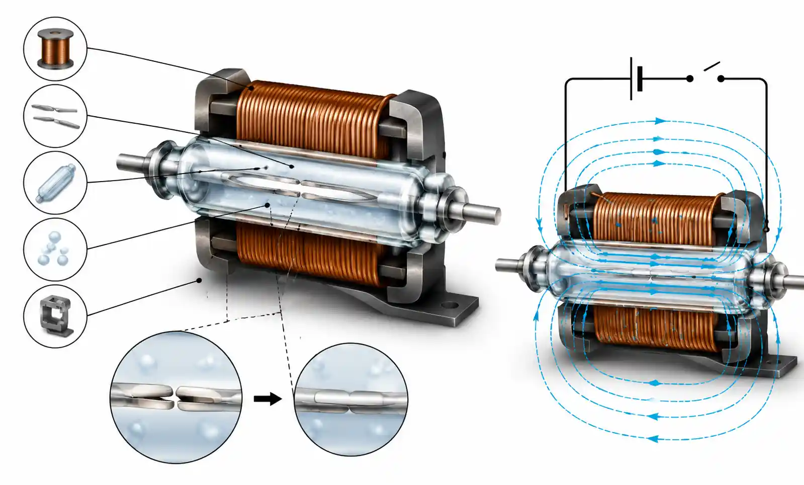
Reed relays combine true galvanic isolation with low contact resistance and minimal power consumption. For PCB design engineers, selecting the right one means understanding operating voltage, contact configuration, switching speed, and environmental ratings. This guide covers what actually matters when specifying reed relays for industrial automation, test equipment, medical devices, and automotive applications.
Table of Contents
- Key Technical Parameters
- How to Choose the Right Reed Relay
- Reed Relays vs Alternatives
- Design Considerations and Common Pitfalls
- Application-Specific Selection
- Supply Chain and Sourcing
- FAQ
- Conclusion
Key Technical Parameters
When evaluating reed relay datasheets, a few parameters make or break your design.
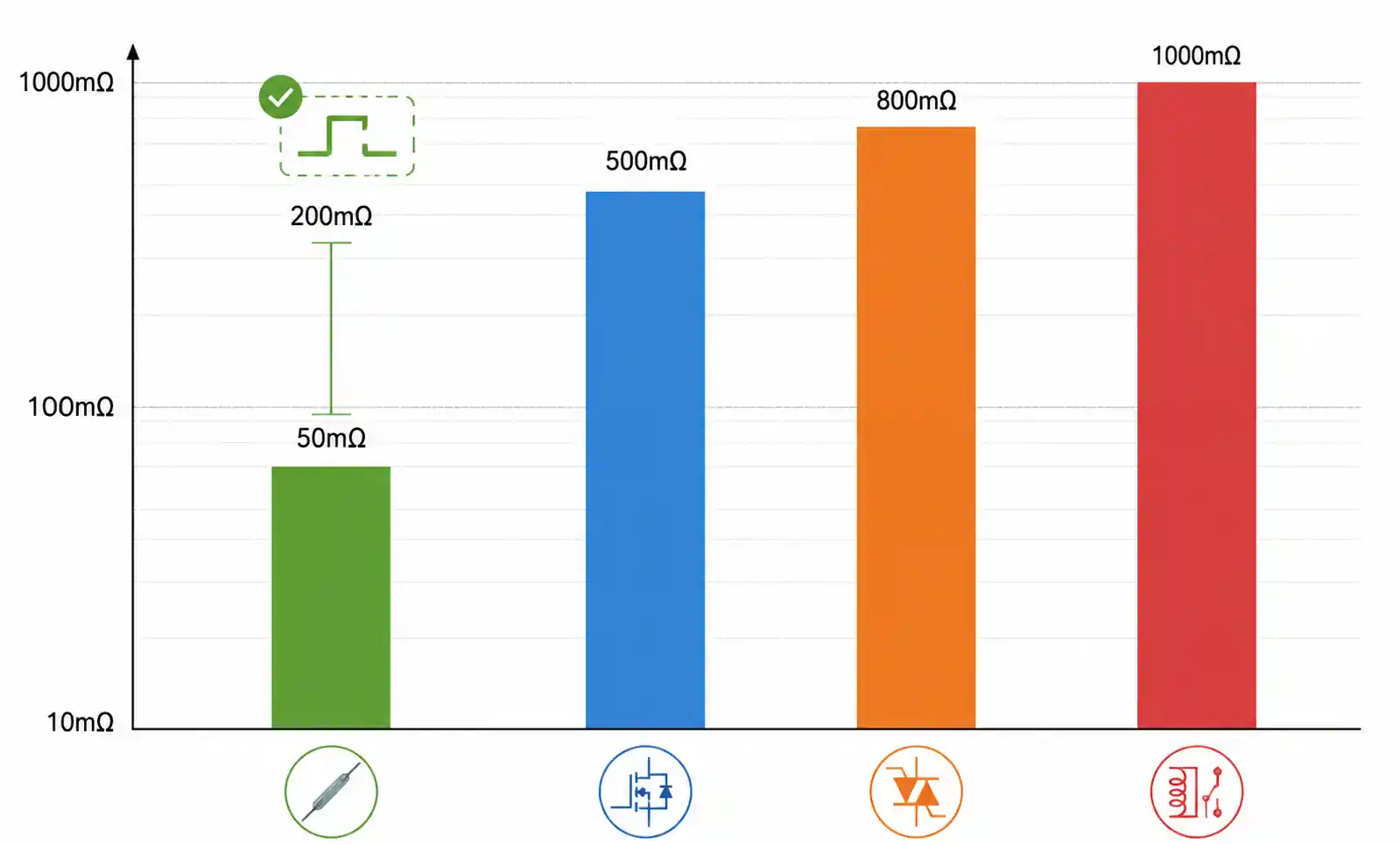
Contact Resistance and Voltage Drop: Typically 50-200mΩ for standard relays. In precision analog circuits or 4-20mA loops, reed relays behave like a true ohmic contact with negligible voltage drop—typically <10mV at rated current. Solid-state alternatives can't match this for low-level signal integrity.
Switching Voltage and Current: Maximum switching voltage commonly ranges from 200V to 500V DC, with switching current from 0.5A to 3A. For inductive loads (solenoids, motors), derate current capacity by 30-50% and always implement transient suppression. The carry current rating—continuous current when closed—is often higher than switching current, which matters in battery management or power distribution applications.
Operate and Release Times: Operate time runs 0.5-2ms; release time 0.1-0.5ms. These determine maximum switching frequency and impact circuit timing in sequential logic. In ATE systems, faster relays (sub-1ms) directly reduce test cycle time.
Contact Configuration: Form A (SPST-NO), Form B (SPST-NC), Form C (SPDT), and multi-pole configurations (2-pole, 4-pole, 8-pole). Multi-pole relays guarantee synchronized switching across multiple signal paths—essential for differential signal routing or multichannel measurement. Verify contact isolation meets your crosstalk requirements for RF or precision analog applications.
Coil Characteristics: Coil voltage (3V, 5V, 12V, 24V) and resistance determine power consumption. Calculate dissipation (V²/R). For battery-powered designs, consider latching reed relays that only need a pulse to change state—standby power drops to near zero.
How to Choose the Right Reed Relay
Step 1: Characterize the load. Nominal voltage and current, load type (resistive, inductive, capacitive), inrush current, duty cycle. For inductive loads, calculate L/R time constant to estimate back-EMF.
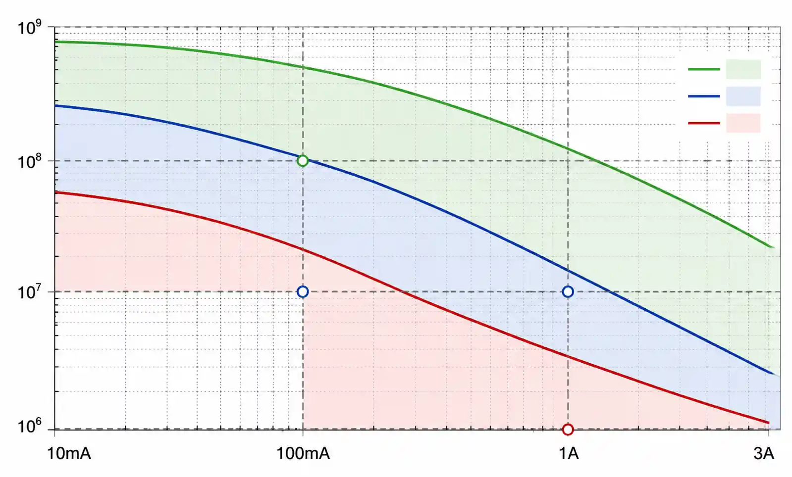
Step 2: Estimate switching frequency and life. Mechanical life ranges from 10⁶ operations (high-power) to 10⁹ (low-level signal). A relay switching once per second for five years = ~157 million operations. If that exceeds 50% of rated life, consider a higher-grade relay or solid-state alternative.
Step 3: Check environmental requirements. Standard reed relays run -40°C to +85°C; extended temperature versions reach +125°C for automotive. For vibration above 10G or shock above 50G, implement mechanical dampening or select enhanced shock-resistant models.
Step 4: Verify isolation and breakdown voltage. Coil-to-contact isolation runs 1kV to 3kV standard, with high-voltage models at 5kV+. For medical (IEC 60601) or industrial safety (IEC 61010), verify isolation meets regulatory requirements with margin.
Step 5: Pick package and mounting. Through-hole (DIL, SIL) offers higher current and better thermal dissipation. SMD enables automated assembly and higher density. For contaminated environments, select sealed packages.
| Application Type | Recommended Specs | Key Considerations |
|---|---|---|
| Low-level signal switching (instrumentation) | R_contact <100mΩ, Thermal EMF <3µV, V_switch <100V, I <500mA | Minimize thermoelectric effects, verify low-level specs |
| Industrial control (PLC I/O) | V_switch 250V AC/DC, I 2A, Life >10⁷ ops | UL/CE certified, arc suppression for inductive loads |
| Automotive electronics | -40°C to +125°C, Shock 50G, AEC-Q200 qualified | Derate for temp cycling, verify automotive grade |
| Test and measurement | Speed <1ms, Stability ±5mΩ, Low thermal EMF | Prioritize repeatability and stability over cost |
| Medical devices | Isolation >4kV, Low leakage, IEC 60601 compliant | Regulatory compliance, verify isolation under humidity |
Reed Relays vs Alternatives
| Parameter | Reed Relay | Solid-State Relay | Engineering Impact |
|---|---|---|---|
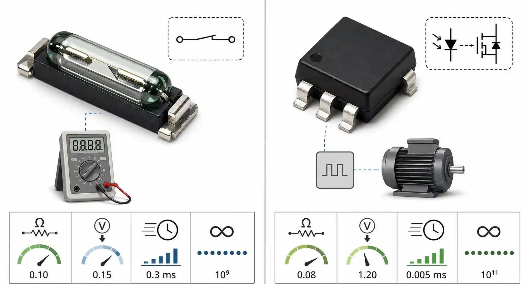
| Contact resistance | 50-200mΩ | 10-100mΩ (MOSFET), >1Ω (TRIAC) | Reed offers lower resistance for signal integrity |
| Voltage drop (closed) | <10mV @ rated current | 0.5-2V typical | SSR drop affects power dissipation and accuracy |
| Off-state leakage | <10pA | 1-100µA typical | Reed essential for high-impedance measurements |
| Switching speed | 0.5-2ms | 1-100µs | SSR faster for high-frequency switching |
| Mechanical life | 10⁶-10⁹ ops | 10⁹-10¹¹ ops | SSR better for continuous high-frequency |
| Current capacity | 0.5-3A | 5-100A | SSR handles higher power |
| Cost (low power) | $2-10 | $5-20 | Reed more economical for low-current apps |
Choose reed relays for: Precision analog signal switching, low-level measurement (<100mV), high off-state isolation (>10¹¹Ω), AC/DC versatility, cost-sensitive low-power applications.
Choose solid-state for: High switching frequency (>10Hz continuous), high vibration, current >5A, silent operation, very long life (>10⁹ ops).
Design Considerations and Common Pitfalls
Contact Protection: Reed relay contacts can weld or erode when switching inductive or capacitive loads without protection. For inductive DC loads, put a flyback diode across the load (cathode to positive). For AC loads or bidirectional switching, use a bidirectional TVS diode rated 1.5× max load voltage. Without suppression, relay life drops from 10⁸ to below 10⁶ operations.
Coil Drive: Never drive reed relay coils directly from microcontroller I/O pins. Use a transistor switch with base/gate resistor. Include a flyback diode (1N4148) across the coil—kickback can reach 10× coil voltage.
PCB Layout: For 250V applications, maintain minimum 2mm creepage distance; for 500V, use 4mm+ per IEC 60664-1. Keep coil drive traces short and away from sensitive analog signals.
Common Mistakes:
- Parallel contacts to increase current rating: Don't do this. Contact resistance variation means uneven current distribution—one contact fails prematurely.
- Ignoring contact bounce: Typical bounce is 0.1-0.5ms. Implement software debouncing (5-10ms delay) or an RC filter + Schmitt trigger.
- Exceeding voltage ratings: Inductive load spikes can be 5-10× supply voltage. A 24V solenoid can generate 200V+ transients—exceeding a 100V-rated relay's breakdown. Always implement suppression.
- Operating at 100% rated current: Continuous operation at rated current reduces life due to heating and material transfer. Derate to 70-80% for high-reliability applications.
Application-Specific Selection
Test and Measurement: ATE and DAQ equipment need low thermal EMF (<3µV), excellent long-term stability (±5mΩ over 10⁷ ops), and fast switching. Select gold-plated contacts. For multiplexers, check channel-to-channel crosstalk (typically -80dB to -100dB at 1MHz). For >10MHz, standard reed relays show significant insertion loss—use RF-specific coaxial or matched-impedance packages.
Industrial Automation: PLC I/O modules need UL508 or IEC 61010 compliance. For 24V DC control circuits, specify positive opening contacts per IEC 61508 functional safety. In high-EMI environments, choose shielded coils to prevent false triggering from external magnetic fields.
Automotive: AEC-Q200 qualification required. Battery management systems need >2kV isolation between adjacent cells and low contact resistance. For sensor applications, select relays with low magnetic sensitivity to prevent interference from nearby motors or alternators.
Medical: IEC 60601-1 compliance requires >4kV coil-to-contact isolation, low leakage current (<2µA at rated voltage), and medical-grade certifications. For implantable or continuous-monitoring devices, select hermetically sealed relays and low-power coil options to extend battery life.
Supply Chain and Sourcing
| Supply Chain Factor | Typical Status | Procurement Strategy |
|---|---|---|
| Standard products (5V, 12V coils, SPST) | 8-12 weeks lead time | Maintain 3-6 month buffer inventory |
| Custom coil voltages or configurations | 12-20 weeks | Lock in annual agreements with forecasting |
| Automotive-grade (AEC-Q200) | 12-16 weeks | Dual-source from multiple manufacturers |
| Obsolescence risk (>10 years in production) | Check lifecycle status | Design with pin-compatible alternatives |
Major manufacturers: Standex-Meder (industry leader, MK series, DIP, SMD), TE Connectivity (PB series, good NA distribution), Coto Technology (high-frequency, test & measurement), Littelfuse/Hamlin (automotive, harsh environment), Pickering Electronics (premium instrumentation, <1µV thermal EMF).
Cost optimization: Standard relays in 1K-10K volumes cost $2-5 each; 10K+ drops to $1-3. SMD packages cost 10-20% more than through-hole. Custom specs (non-standard voltage, special contacts) add 30-50% and require 5K-10K MOQ.
FAQ
What is the typical lifespan of a reed relay?
10⁶ to 10⁹ operations depending on contact load. Low-level signal switching (dry contacts, <10V, <10mA) achieves the longest life. Switching inductive loads at rated current significantly reduces life. Calculate total operations over product lifetime and ensure it stays below 50% of datasheet rating with derating for load type and environmental stress.
How do I calculate the required flyback diode for the coil?
Select a diode with reverse voltage rating >2× coil supply voltage and forward current rating ≥ steady-state coil current. For most reed relays (5-30mA coil current), a 1N4148 (100V, 200mA) works. For higher current coils (>100mA), use 1N4007 (1000V, 1A). Reverse recovery time isn't critical—coil switching happens at low frequencies.
Can reed relays switch AC and DC loads?
Yes. For AC switching, verify the relay's AC voltage rating (specified as VRMS) and ensure peak voltage (1.414× VRMS) doesn't exceed maximum switching voltage. AC switching generally gives longer contact life than DC at equivalent power levels because zero-crossing reduces arcing.
What causes contact welding and how do I prevent it?
Excessive current melts contact surfaces and fuses them together. Primary causes: switching inductive loads without suppression, capacitive inrush current, hot-switching high currents, and mechanical shock during closure. Prevent by implementing arc suppression (diodes for DC, MOVs for AC), limiting inrush current with series resistance, derating current by 20-30%, and avoiding high-shock mounting locations.
How do I select the appropriate contact material?
Ruthenium (most common) offers good balance of contact resistance, switching capacity, and cost. Rhodium provides lower resistance and better corrosion resistance for low-level signals at higher cost. Tungsten handles higher currents but has higher resistance. For signal switching below 100mV or 10mA, specify gold-plated contacts to prevent oxide formation that increases resistance over time.
What is thermal EMF and when does it matter?
Thermal EMF is a small voltage generated at the junction of dissimilar metals when a temperature gradient exists—typically 1-5µV/°C in reed relays. This matters in precision measurement applications (thermocouples, strain gauge bridges, nanovolt measurements) where relay thermal EMF can introduce errors comparable to or larger than the signal. Specify relays with <3µV thermal EMF for high-accuracy applications.
Can I use reed relays in high-vibration environments?
Standard relays withstand 10-20G continuous vibration but may experience contact chatter under higher levels. For vibration above 10G or shock above 50G (automotive, aerospace), select vibration-resistant relays with mechanical damping, or consider solid-state alternatives. Implement mechanical isolation (rubber grommets, shock mounts) and orient the relay so vibration is perpendicular to the contact axis.
How do I interpret the maximum switching power specification?
Maximum switching power (watts or VA) represents the product of voltage and current the relay can safely switch. But you must verify both voltage and current remain within individual maximum ratings—you can't trade higher voltage for lower current beyond the rating, or vice versa. For example, a relay rated 10W, 250V, 0.5A can switch 10W at lower voltages, but can't exceed 0.5A regardless of voltage, and can't exceed 250V even at low current.
Conclusion
Reed relay selection balances electrical performance, mechanical reliability, environmental robustness, and cost. For precision measurement, prioritize low thermal EMF and contact stability. For industrial control, focus on regulatory compliance, mechanical life, and vibration resistance. Automotive demands wide temperature operation and AEC-Q200. Medical requires high isolation and low leakage.
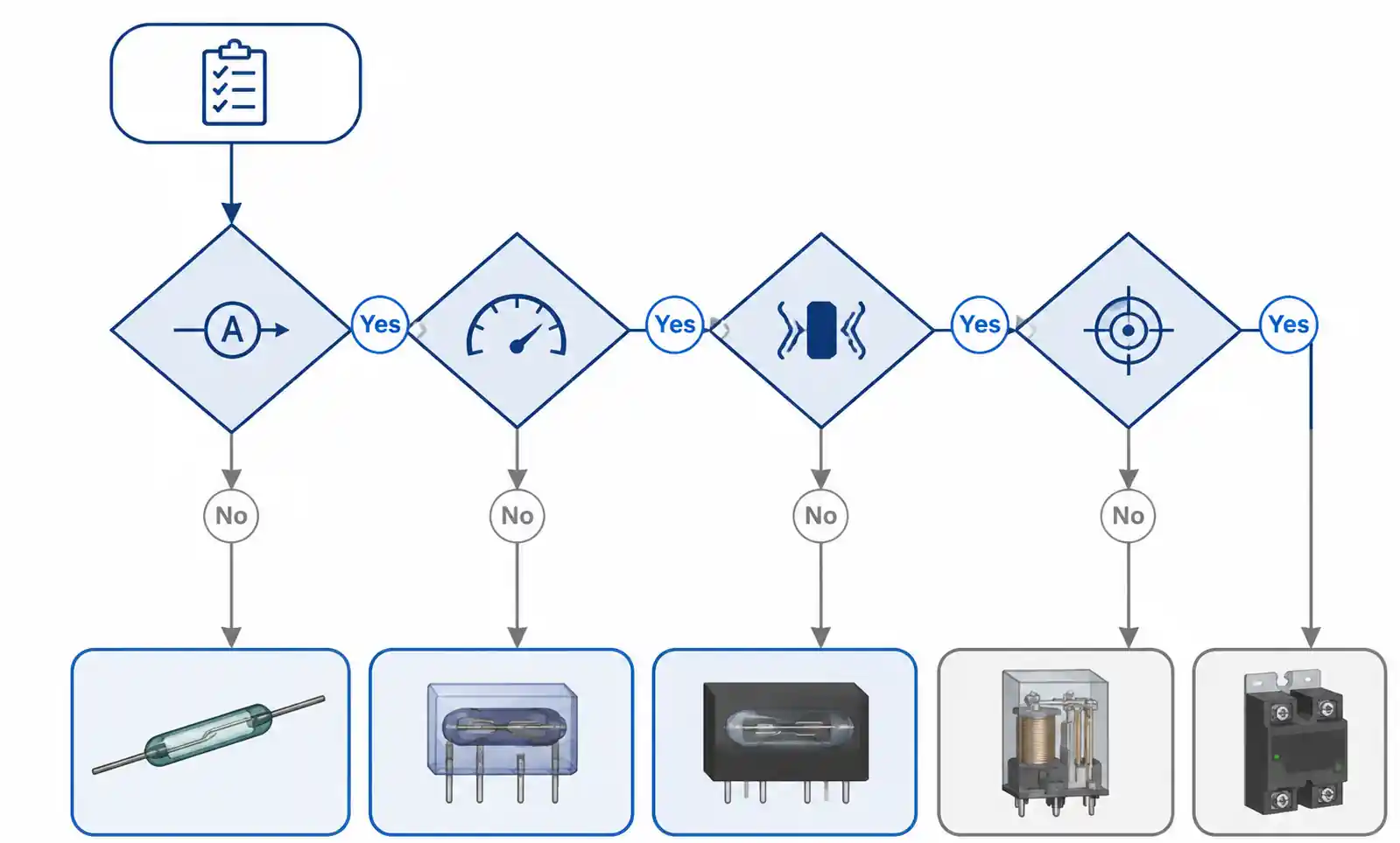
Before finalizing: verify maximum switching voltage and current with derating for load type; coil voltage and power dissipation compatible with your drive circuit; mechanical life exceeding expected operations with margin; environmental ratings meeting application requirements; regulatory certifications; and availability of second sources to mitigate supply chain risk.
