




RS-485 Transceiver Selection for Industrial Automation
RS-485 transceivers power over 60% of factory automation networks in 2026. Selecting the right transceiver requires balancing data rate, network topology, protection features, and environmental conditions for reliable operation in harsh industrial environments.
Table of Contents
- RS-485 Fundamentals
- RS-485 vs RS-422
- Critical Selection Parameters
- Data Rate and Cable Length
- Network Topology and Termination
- Protection and Isolation
- Transceiver Comparison
- Sourcing Recommendations
- FAQ
- Conclusion
RS-485 Fundamentals
RS-485 is a differential signaling standard (TIA/EIA-485-A) enabling robust serial communication over long distances in electrically noisy industrial environments. Data transmits as voltage difference between two wires (A and B), providing excellent common-mode noise rejection.
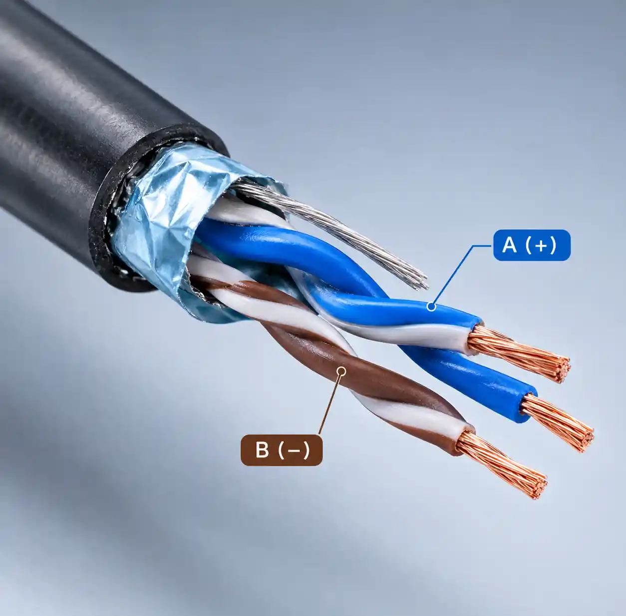 RS-485 differential signaling on twisted pair cable showing A and B lines
Differential signaling offers superior noise immunity versus single-ended standards like RS-232. When electromagnetic interference affects both wires equally, the receiver detects only the voltage difference, effectively canceling common-mode noise. This makes RS-485 ideal for factory floors with variable frequency drives, motors, and switching power supplies.
RS-485 supports multi-drop topology with up to 32 devices (standard) or 256 devices (1/8 unit load transceivers). Communication distances reach 1,200 meters at lower data rates, far exceeding RS-232's 15-meter limit. Modern industrial automation applications including Modbus RTU, PROFIBUS, and building management systems rely on RS-485 for field-level communication.
RS-485 vs RS-422
RS-485 and RS-422 both use differential signaling but differ in network topology and driver capabilities.
| Parameter | RS-422 | RS-485 | Key Difference |
|---|---|---|---|
| Network Topology | Point-to-multipoint | Multi-point | RS-485 supports multi-drop |
| Duplex Mode | Full-duplex (4 wires) | Half or full-duplex | RS-485 more flexible |
| Driver Count | Single driver | Up to 32 drivers | RS-485 bidirectional |
| Common Mode Range | -7V to +7V | -7V to +12V | RS-485 wider range |
RS-422 uses separate differential pairs for transmit and receive (4 wires), with one driver and up to 10 receivers per pair. RS-485 enhanced RS-422 by adding tri-state drivers, allowing multiple transmitters to share one bus. Drivers enter high-impedance when not transmitting, preventing bus contention.
Choose RS-422 for dedicated point-to-multipoint communication with guaranteed full-duplex operation. Choose RS-485 for multi-drop industrial networks where any device might initiate communication, including Modbus RTU and distributed control systems.
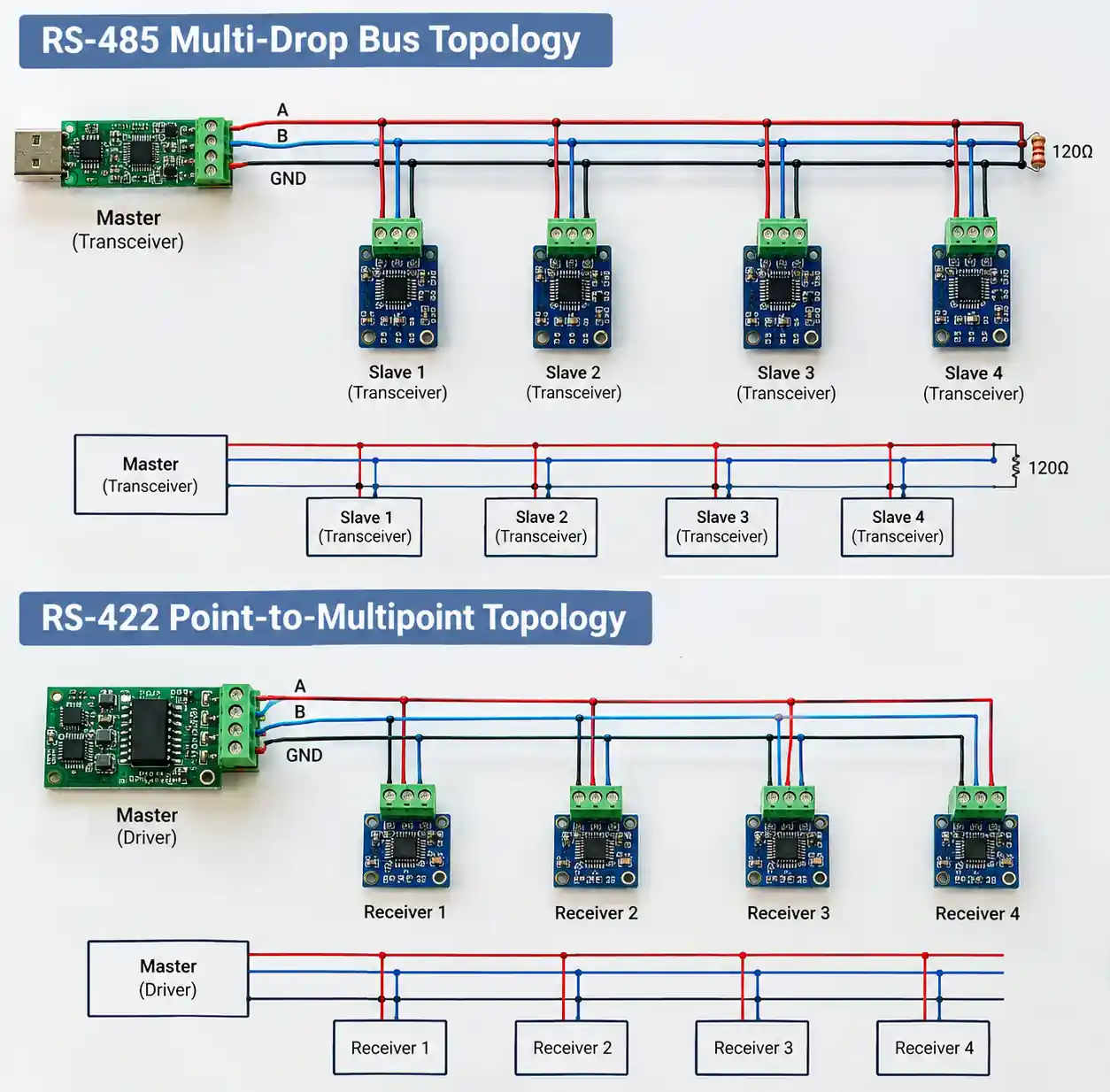 RS-485 multi-drop network topology compared to RS-422 point-to-multipoint
Critical Selection Parameters
Key specifications impact network reliability and performance:
Supply Voltage: 3.3V for modern microcontrollers/FPGAs, 5V for legacy PLCs. Low-power variants draw 200µA-500µA in shutdown for battery applications.
Driver Output: Minimum 1.5V differential (RS-485 standard). Quality transceivers provide 2.5V-5V for noise margin. Output current (50-60mA) determines unit loads—32 devices standard, 256 with 1/8 unit load transceivers.
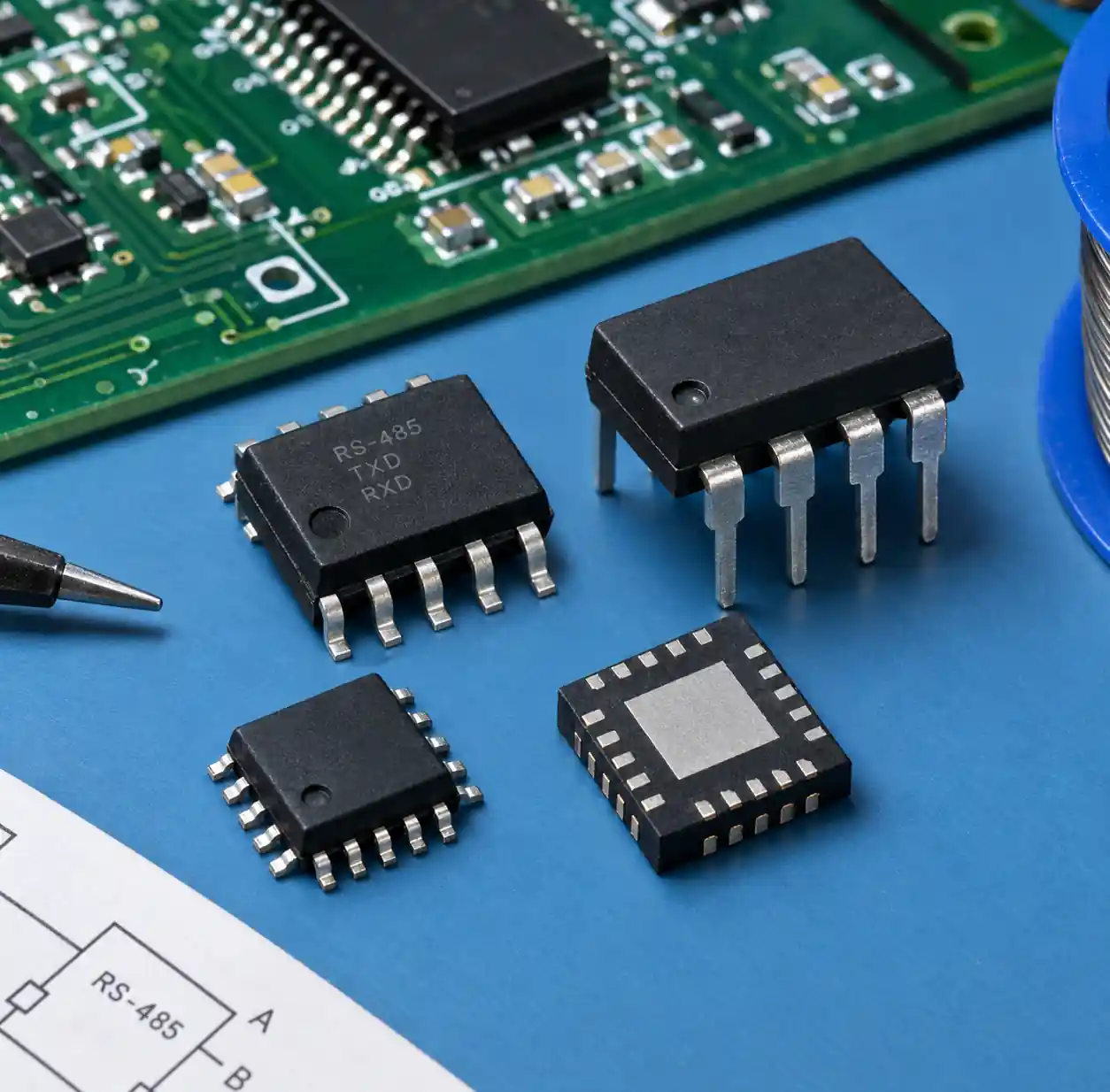 RS-485 transceiver integrated circuits in various package types
Receiver Sensitivity: 200mV minimum detection threshold. Hysteresis (30-70mV) prevents false triggering from noise but reduces sensitivity over long cables.
Common Mode Range: Standard -7V to +12V handles ground potential differences. Extended range (-12V to +12V) essential for multi-building networks.
Data Rate: Standard transceivers support up to 500 kbps. High-speed variants achieve 10-50 Mbps over short distances. Slew-rate limiting reduces EMI but caps speed around 250 kbps.
Data Rate and Cable Length
RS-485 networks face trade-offs between communication speed and cable distance due to signal attenuation and capacitive loading.
| Cable Length | Maximum Data Rate | Typical Application |
|---|---|---|
| 10 meters | 10 Mbps | Machine-to-machine |
| 100 meters | 1 Mbps | Factory floor networks |
| 500 meters | 250 kbps | Building automation |
| 1,000 meters | 100 kbps | Campus-wide networks |
| 1,200 meters | 9.6-50 kbps | Remote monitoring |
The speed-distance relationship approximates: data rate (bit/s) × cable length (m) ≤ 10⁸. Cable capacitance (40-60 pF/m) accumulates with length, causing signal distortion. At 1,200 meters, total capacitance reaches 48-72 nF, significantly attenuating high-frequency components.
You can extend distance beyond 1,200 meters using RS-485 repeaters that regenerate signals. Repeaters add 1-10µs latency and provide electrical isolation for multi-building installations. Industrial deployments typically use 500 meters at 250 kbps for factory automation with 24 AWG twisted-pair cable.
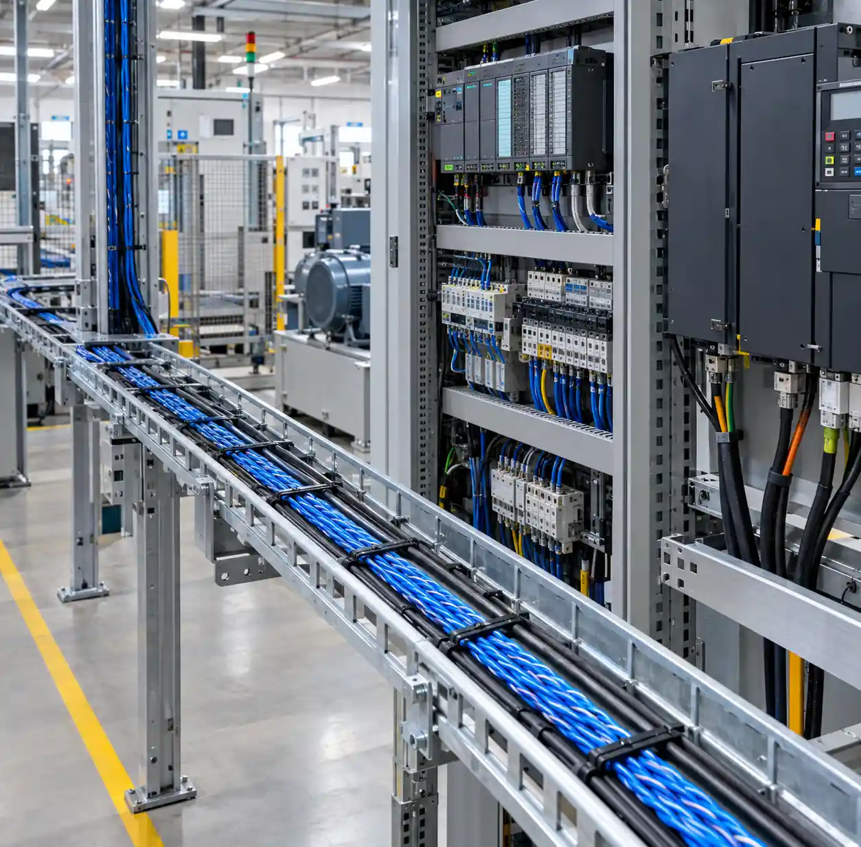 Industrial RS-485 cable installation in factory automation environment
Network Topology and Termination
RS-485 supports 32 standard unit loads or up to 256 devices using 1/8 unit load transceivers. The network requires bus (daisy-chain) topology with 120Ω termination resistors at both physical ends to prevent signal reflections. Stub cables connecting devices to the trunk must not exceed 0.3 meters.
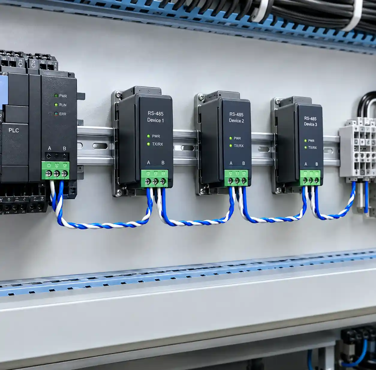 RS-485 bus topology showing daisy-chain device connections
Place one 120Ω resistor between A and B at each network end—typically at the master and last slave device. Star topology creates signal reflections and fails at higher data rates; use RS-485 hubs if star wiring is required.
RS-485 bus topology showing daisy-chain device connections
Place one 120Ω resistor between A and B at each network end—typically at the master and last slave device. Star topology creates signal reflections and fails at higher data rates; use RS-485 hubs if star wiring is required.
| Termination Type | Configuration | Use Case | Advantages |
|---|---|---|---|
| Simple Resistor | 120Ω across A-B | Short networks (<100m) | Lowest cost |
| RC Network | 120Ω + 1nF | High-speed networks | Better impedance match |
| Bias + Termination | Pull-up/down + 120Ω | Idle networks | Fail-safe operation |
Fail-safe biasing (560Ω-680Ω pull-up on A, pull-down on B) prevents floating bus conditions when all drivers are disabled, maintaining ~200mV differential during idle periods.
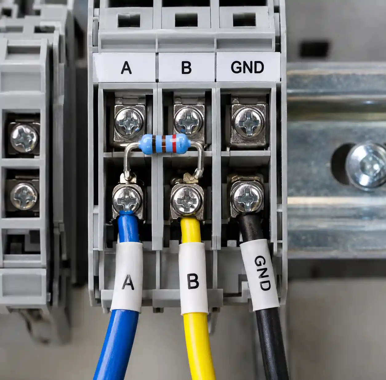 RS-485 termination resistor installed at network endpoint terminal block
Field data shows 60% of intermittent failures result from incorrect termination. Verify with a multimeter: measure ~60Ω between A and B at network ends (two 120Ω in parallel). Improper topology accounts for 35% of RS-485 network failures.
ESD Protection and Isolation Options
Industrial environments expose RS-485 interfaces to multiple transient threats including electrostatic discharge (ESD), electrical fast transients (EFT), and surge events from lightning or inductive load switching. Proper protection prevents costly equipment damage and ensures network reliability.
ESD Protection Levels
RS-485 transceivers specify ESD protection using Human Body Model (HBM) and IEC 61000-4-2 standards. Basic transceivers provide ±8 kV HBM protection, adequate for controlled indoor environments. Industrial-grade transceivers offer ±15 kV to ±25 kV IEC 61000-4-2 contact discharge protection and ±30 kV air discharge protection, essential for factory automation and outdoor installations.
You can add external TVS (Transient Voltage Suppressor) diodes to transceivers with basic protection. Place low-capacitance TVS diodes (typically 5 pF to 15 pF) between each bus line and ground near the transceiver pins. TVS diodes clamp voltage spikes to safe levels but add parasitic capacitance that limits maximum data rate and cable length.
Galvanic Isolation
Isolated RS-485 transceivers incorporate transformers or capacitive isolation barriers that eliminate galvanic connection between the bus-side and logic-side circuits. Isolation prevents ground loops and protects equipment from common-mode voltage transients that exceed the transceiver's common-mode range.
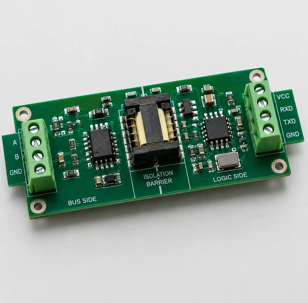 Isolated RS-485 transceiver module with galvanic isolation barrier
Isolation ratings range from 2.5 kV to 5 kV continuous working voltage. Industrial applications spanning multiple buildings or areas with unreliable ground connections should specify isolated transceivers rated for at least 2.5 kV isolation. Medical equipment and applications requiring regulatory compliance may require 5 kV isolation per IEC 60601.
| Protection Feature | Standard Transceiver | Protected Transceiver | Isolated Transceiver |
|---|---|---|---|
| ESD (HBM) | ±8 kV | ±15 kV | ±15 kV |
| ESD (IEC 61000-4-2) | Not specified | ±12 kV to ±25 kV | ±12 kV to ±25 kV |
| Galvanic Isolation | None | None | 2.5 kV to 5 kV |
| Cost Multiplier | 1x | 1.5x to 2x | 3x to 5x |
| Use Case | Controlled indoor | Industrial automation | Multi-building, outdoor |
Integrated isolated transceivers like ADM2795E and similar devices from major manufacturers combine isolation, ESD protection, and RS-485 transceiver in a single package. These solutions simplify board design compared to discrete isolation components but cost more than non-isolated alternatives.
According to protection circuit analysis from Texas Instruments and Analog Devices application notes, the external protection network must be carefully matched to the transceiver's internal ESD structures to avoid creating new failure modes. Generic TVS diode selection without engineering analysis can degrade rather than improve reliability.
Half-Duplex vs Full-Duplex Operation
RS-485 supports both half-duplex and full-duplex communication modes. The mode selection impacts wiring complexity, protocol overhead, and effective throughput for your industrial automation application.
Half-Duplex (2-Wire) Operation
Half-duplex RS-485 uses a single differential pair for bidirectional communication. Devices share the same two wires (A and B) plus ground reference. Only one device transmits at any time while all others receive. The transmitting device drives the bus while its receiver typically remains enabled to detect collision conditions.
Half-duplex requires protocol-level arbitration to prevent bus contention. Modbus RTU uses master-slave protocol where only the master initiates communication, eliminating contention. Other protocols implement token passing or CSMA/CD (Carrier Sense Multiple Access with Collision Detection) mechanisms.
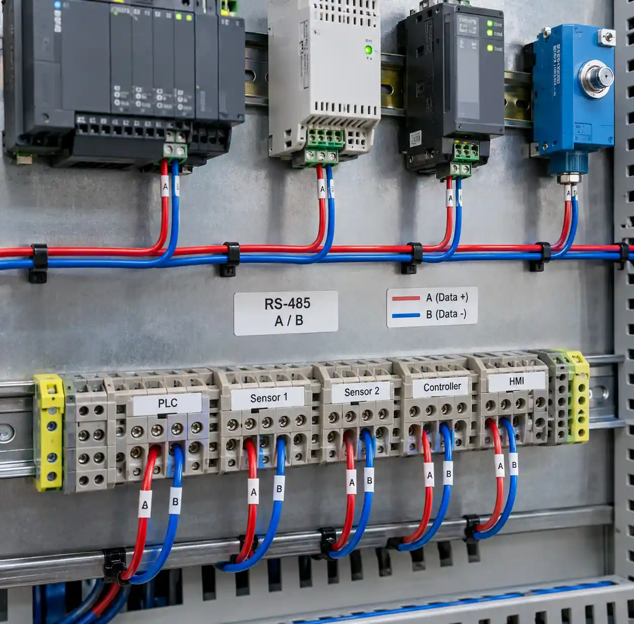 RS-485 half-duplex two-wire communication setup with multiple devices
The key advantage of half-duplex is minimal wiring cost and complexity. You need only one twisted pair plus ground or shield conductor. Installation and troubleshooting are simpler because fewer connections reduce failure points. Half-duplex RS-485 dominates industrial automation installations, representing over 90% of deployed networks.
Full-Duplex (4-Wire) Operation
Full-duplex RS-485 uses two differential pairs: one dedicated for transmit and one for receive. Each device can transmit and receive simultaneously without protocol-level collision management. This configuration resembles RS-422 but uses RS-485 transceivers for better common-mode range and multi-drop capability.
Full-duplex eliminates turnaround time delays that occur in half-duplex when switching between transmit and receive modes. For protocols with frequent back-and-forth communication, full-duplex can increase effective throughput by 30% to 50% compared to half-duplex at the same baud rate.
The tradeoff is doubled wiring cost and complexity. You need four signal wires plus ground or shield, increasing cable cost and installation labor. Full-duplex also requires more I/O pins on each device and doubles the number of termination resistors needed.
You should specify half-duplex RS-485 for standard industrial automation networks using Modbus RTU or similar master-slave protocols. Consider full-duplex only when simultaneous bidirectional communication provides significant throughput advantage and the added wiring cost is justified.
Industrial Temperature Range Considerations
Industrial RS-485 transceivers must operate reliably across wide temperature ranges encountered in factory automation, outdoor installations, and automotive applications. Temperature affects both transceiver electrical parameters and long-term reliability.
Temperature Grade Classifications
Commercial grade components specify 0°C to +70°C operating temperature, adequate for climate-controlled indoor environments like server rooms and office automation. Industrial grade extends the range to -40°C to +85°C, handling most factory floor and building automation applications. Automotive grade components meet AEC-Q100 qualification and operate from -40°C to +125°C or -40°C to +150°C for Grade 0 devices.
You should specify industrial or automotive grade transceivers for applications exposed to temperature extremes, including outdoor enclosures, motor control centers, and equipment mounted near heat-generating machinery. The additional cost (typically 20% to 40% premium) prevents field failures from thermal stress.
Temperature Effects on Electrical Parameters
RS-485 driver output voltage decreases at high temperature as transistor saturation voltage increases. Quality transceivers maintain specifications across the full temperature range, but marginal designs may violate the 1.5V minimum differential output at +85°C. Receiver input offset voltage also varies with temperature, potentially causing threshold shifts that affect noise margin.
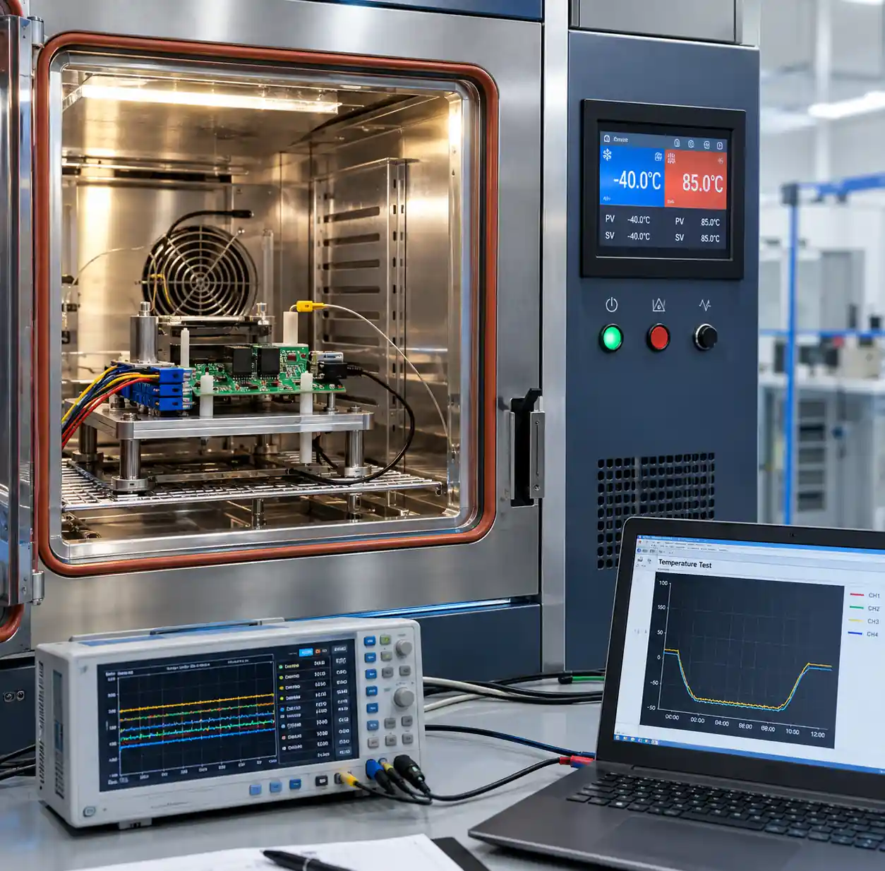 Industrial-grade RS-485 transceiver undergoing temperature range testing
Characteristic impedance of twisted-pair cable changes approximately 0.1% per °C due to dielectric constant variation. Over industrial temperature range (-40°C to +85°C), cable impedance can shift ±12% from nominal 120Ω value. This variation typically does not cause problems because termination resistor tolerance (±5% or ±10%) already accounts for impedance variation.
According to reliability engineering analysis, component failure rate doubles approximately every 10°C temperature increase above rated maximum. Operating a commercial-grade transceiver at +85°C in a factory environment can reduce MTBF (Mean Time Between Failures) by a factor of 8 compared to operation at +25°C. This accelerated aging causes premature failures and increased maintenance costs.
For procurement managers sourcing electronic components for industrial automation projects, temperature rating should be a primary selection criterion. The incremental cost of industrial-grade components is negligible compared to the expense of field failures and emergency replacement in deployed systems.
Transceiver Comparison Table
| Feature | Standard RS-485 | High-Speed RS-485 | Isolated RS-485 | Automotive RS-485 |
|---|---|---|---|---|
| Data Rate | Up to 500 kbps | 10 Mbps to 50 Mbps | Up to 500 kbps | Up to 1 Mbps |
| Max Distance | 1,200 meters | 10 to 100 meters | 1,000 meters | 100 meters |
| Temperature Range | -40°C to +85°C | -40°C to +85°C | -40°C to +85°C | -40°C to +125°C/+150°C |
| ESD Protection | ±8 kV HBM | ±15 kV HBM | ±15 kV IEC 61000-4-2 | ±25 kV IEC 61000-4-2 |
| Isolation | None | None | 2.5 kV to 5 kV | None (usually) |
| Unit Load | 1 or 1/8 | 1 | 1 or 1/8 | 1 |
| Cost per Unit | $0.30 - $1.00 | $1.50 - $3.00 | $3.00 - $8.00 | $1.00 - $2.50 |
| Best For | General industrial | High-speed machine control | Multi-building, outdoor | Automotive ECU networks |
Sourcing Recommendations
Industrial automation projects require RS-485 transceivers from authorized distributors to ensure authentic components and regulatory compliance. Counterfeit transceivers represent a significant risk in the electronic component supply chain, with failure rates 20x to 100x higher than genuine parts.
When planning RS-485 component procurement for industrial projects, you should consider lead times ranging from 8 to 16 weeks depending on manufacturer and package type. Popular industrial-grade transceivers like MAX3485, SN75176, and ADM485 maintain better availability than specialized high-speed or isolated variants.
Volume procurement offers significant cost advantages. Standard RS-485 transceivers purchased in 1,000-piece quantities cost 30% to 50% less per unit than 100-piece orders. For large deployments, consider supplier consolidation to qualify for volume pricing while simplifying supply chain management and quality verification.
If you need reliable RS-485 transceivers for industrial automation projects, Hitop Tech offers comprehensive procurement services with global sourcing network across Asia, Europe, North America, and Africa. Our authorized distributor relationships ensure authentic components with full traceability and compliance documentation. We have successfully served customers in Southeast Asia and Africa markets, achieving cost reductions of 20% to 40% through supplier consolidation and strategic sourcing while maintaining quality and delivery reliability.
FAQ
What is the maximum distance for RS-485 communication?
RS-485 standard specifies maximum cable length of 1,200 meters at lower data rates (9.6 kbps to 50 kbps). Practical distance depends on cable quality, data rate, and electromagnetic environment. You can extend distance beyond 1,200 meters using RS-485 repeaters with signal regeneration.
Can I mix 5V and 3.3V RS-485 transceivers on the same network?
Yes, RS-485 transceivers with different supply voltages can interoperate on the same bus because the standard defines differential voltage levels independent of supply voltage. Both 5V and 3.3V transceivers meet the minimum ±1.5V differential output requirement. Verify that each transceiver's common-mode range is compatible with the bus voltage levels.
How many devices can connect to one RS-485 network?
Standard RS-485 supports 32 unit load devices per segment. You can increase this to 256 devices using 1/8 unit load transceivers or add more devices by using RS-485 repeaters to create multiple segments. Each repeater isolates network segments electrically while forwarding data between them.
Do I need isolation for indoor RS-485 networks?
Isolation is not required for RS-485 networks within a single building with reliable earth ground connections. You should specify isolated transceivers for networks spanning multiple buildings, outdoor installations, or applications where ground potential differences might exceed ±7V to ±12V common-mode range. Isolation also provides protection against lightning-induced transients and improves EMC performance.
What causes intermittent RS-485 communication errors?
Common causes include incorrect or missing termination resistors (60% of intermittent failures), excessive cable length for the data rate, improper network topology (star wiring instead of bus), loose connections, and electromagnetic interference from nearby power cables or motors. Use oscilloscope to examine signal quality and verify termination resistance with a multimeter.
Can RS-485 work without a ground connection?
RS-485 differential signaling does not require a dedicated ground wire for signal transmission. However, a ground reference or shield connection helps maintain common-mode voltage within the transceiver's specified range and improves EMC performance. Long cable runs or electrically noisy environments benefit from connecting cable shield to ground at one end to provide surge current return path.
Conclusion
RS-485 transceiver selection for industrial automation requires careful evaluation of data rate, cable length, node count, protection features, and environmental conditions. The key considerations include matching transceiver speed rating to your network distance requirements, specifying appropriate ESD protection and isolation for your installation environment, and ensuring proper termination and network topology for reliable signal integrity.
Industrial-grade transceivers with -40°C to +85°C temperature range and enhanced ESD protection provide the reliability required for factory automation, building management systems, and outdoor installations. For multi-building networks or applications with significant ground potential differences, isolated transceivers prevent equipment damage and communication failures.
Contact us today for RS-485 transceiver sourcing, technical selection support, and supply chain optimization for your industrial automation projects.
