


Servo Motor Selection Guide: How to Choose the Right Motor for Precision Motion Control
Selecting the right servo motor for your application can make the difference between a system that delivers precise, reliable performance and one that struggles with positioning errors, overheating, or premature failure. Whether you're designing a robotic arm, CNC machine, automated packaging line, or medical device, understanding servo motor parameters and selection criteria is essential for engineers and procurement teams alike.
This guide walks you through the technical fundamentals, key selection parameters, performance trade-offs, and design considerations you need to specify and source the optimal servo motor for your motion control application.
Table of Contents
- What is a Servo Motor and How Does It Work?
- Key Technical Parameters for Servo Motor Selection
- How to Calculate Required Torque and Inertia
- Servo Motor vs. Stepper Motor: When to Use Which
- Design Considerations and Common Pitfalls
- Supply Chain and Sourcing Considerations
- FAQ
- Conclusion
1. What is a Servo Motor and How Does It Work?
A servo motor is a rotary or linear actuator that provides precise control of angular or linear position, velocity, and acceleration. Unlike standard motors that simply spin when powered, servo motors incorporate a feedback device—typically an encoder or resolver—that continuously reports the actual shaft position back to the controller.
This closed-loop control architecture allows the servo system to detect and correct positioning errors in real time. When the controller sends a position command, the drive compares the commanded position with the encoder feedback. Any deviation generates an error signal that the drive uses to adjust motor current, bringing the shaft to the exact target position.
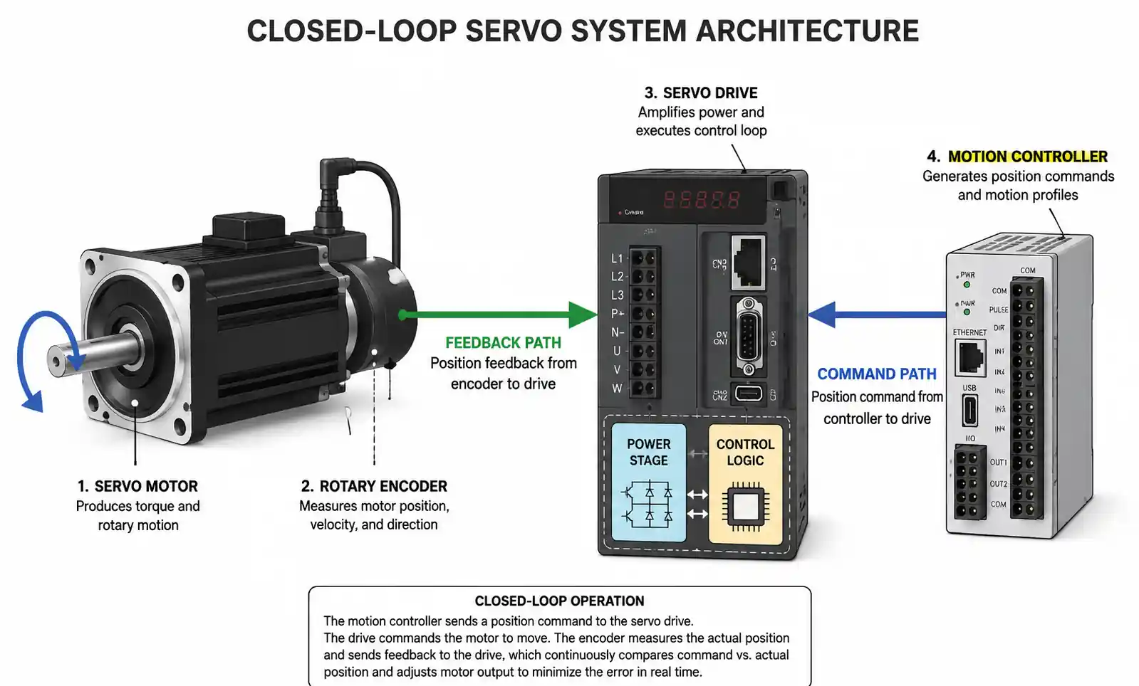
The core components of a servo system include the motor itself, an encoder or resolver for position feedback, a servo drive that interprets commands and regulates current, and a motion controller that generates trajectory profiles. In industrial applications, servo motors are valued for their ability to execute complex motion profiles with high acceleration, rapid settling times, and repeatable positioning accuracy down to arc-seconds.
Servo motors are available in both AC and DC variants. AC servo motors dominate industrial automation due to their higher power density, better thermal performance, and brushless design that eliminates maintenance. DC servo motors remain common in lower-power applications and legacy systems, though brushless DC servo motors (BLDC) have largely replaced brushed designs in new equipment.
2. Key Technical Parameters for Servo Motor Selection
Selecting the right servo motor requires understanding how each specification impacts your application's performance, reliability, and cost. The following parameters form the foundation of any servo motor selection decision.
Torque Specifications
Rated torque (continuous torque) defines the maximum torque the motor can deliver continuously without overheating. This is the torque available for sustained operation and should exceed your application's average torque requirement with adequate margin. Peak torque (maximum torque) represents the short-duration torque available for acceleration, deceleration, or overcoming instantaneous load spikes, typically 2 to 3 times the rated torque.
When sizing for torque, account for friction losses, gravitational loads (for vertical axes), acceleration torque, and a safety factor of 1.2 to 1.5. Undersizing torque leads to missed steps, positioning errors, and drive faults; oversizing wastes capital and panel space.
Speed Range
Rated speed indicates the motor's maximum continuous speed at rated torque. Beyond this speed, available torque decreases due to back-EMF limitations in AC servo motors. Maximum speed defines the absolute speed limit, though torque may be significantly reduced at this point.
For applications requiring constant torque across a wide speed range, consider motors with field-weakening capability or gearbox reduction. High-speed applications demand careful attention to mechanical balance, bearing selection, and encoder resolution.
Inertia and Inertia Ratio
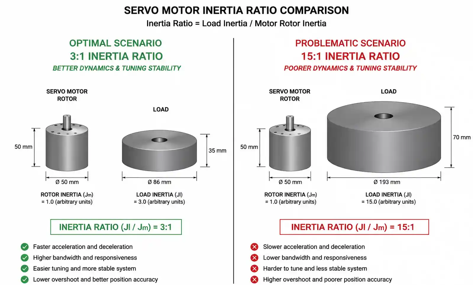
Motor inertia (rotor inertia) measures the resistance of the rotor to angular acceleration. Load inertia represents the reflected inertia of all moving components attached to the motor shaft. The inertia ratio (load inertia divided by motor inertia) critically affects system dynamics and tuning stability.
Traditional design practice targets an inertia ratio between 1:1 and 10:1 for optimal tuning and response. Ratios above 10:1 can lead to sluggish response, overshoot, and difficulty achieving stable tuning. Modern servo drives with advanced tuning algorithms can handle higher ratios, but lower ratios generally yield better performance.
Encoder Resolution
Encoder resolution determines positioning accuracy and feedback precision. Common encoder types include incremental encoders (measuring relative position via quadrature pulses), absolute encoders (reporting absolute position even after power loss), and resolvers (analog devices with high noise immunity). Resolution is specified in counts per revolution (CPR) or bits for absolute encoders.
Higher resolution improves positioning accuracy and enables smoother motion at low speeds, but increases system cost and data processing requirements. For precision positioning applications, 17-bit to 23-bit absolute encoders are common; for less demanding tasks, 13-bit to 16-bit encoders suffice.
Electrical Specifications
Rated voltage and current define the motor's electrical operating point and determine drive compatibility. Common industrial voltages include 230VAC single-phase and 400VAC three-phase for AC servo motors. The motor constant (Kt) relates current to torque, while the voltage constant (Ke) relates speed to back-EMF.
Thermal characteristics include thermal resistance and thermal time constant, which determine how quickly the motor heats under load and cools during idle periods. Proper thermal management is essential for continuous-duty applications.
| Parameter | Typical Range | Selection Criterion |
|---|---|---|
| Rated Torque | 0.05 Nm – 100 Nm+ | Must exceed average load torque by 20-50% |
| Peak Torque | 2x – 3x rated torque | Must handle acceleration and deceleration peaks |
| Rated Speed | 1000 – 6000 rpm | Should exceed maximum application speed by 10-20% |
| Inertia Ratio | 1:1 – 10:1 (optimal) | Lower ratios improve tuning and response |
| Encoder Resolution | 13-bit – 23-bit | Higher resolution for precision positioning |
| Voltage | 230 VAC / 400 VAC | Must match available power supply |
After reviewing this table, verify that your selected motor provides adequate torque margin at the maximum required speed. Many applications fail because engineers size for peak torque without checking whether that torque is available at the operating speed.
3. How to Calculate Required Torque and Inertia
Accurate torque and inertia calculations prevent undersizing (leading to positioning errors and drive faults) and oversizing (wasting capital and complicating tuning). The following methodology applies to the majority of rotary servo applications.
Torque Calculation
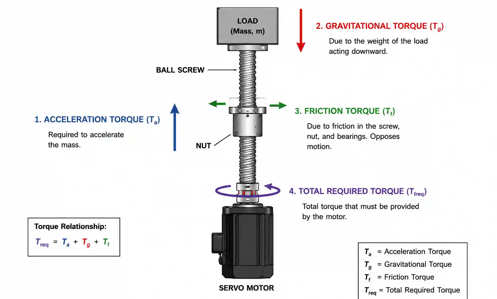
Total required torque consists of four components: acceleration torque, friction torque, gravitational torque (for vertical or inclined axes), and process torque (cutting forces, material resistance, etc.).
Acceleration torque is calculated as: T_accel = J_total × α, where J_total is the total system inertia (motor plus load) and α is the angular acceleration in rad/s². For linear axes with ball screws or belt drives, reflect linear mass and acceleration to the motor shaft using the mechanical advantage.
Friction torque includes bearing friction, seal drag, and sliding friction. For ball screws, friction torque is typically 5-10% of the gravitational and process torque. For belt drives, friction losses range from 15-30% depending on belt tension and pulley bearing quality.
Gravitational torque for vertical axes is: T_grav = m × g × r, where m is the load mass, g is gravitational acceleration (9.81 m/s²), and r is the effective radius (for example, screw lead divided by 2π for ball screws).
Process torque depends on the application—cutting forces in CNC machines, material tension in web handling, or gripping force in robotics. Consult application-specific engineering data for these values.
Add all four components and apply a safety factor of 1.2 to 1.5 to account for model uncertainties, manufacturing tolerances, and aging.
Inertia Calculation
Calculate the reflected inertia of each moving component using standard formulas: for rotating cylindrical masses, J = 0.5 × m × r²; for linear masses moving through a screw, J = m × (lead / 2π)²; for belt-driven linear masses, J = m × r² where r is the pulley radius.
Sum all reflected load inertias and compare to the motor's rotor inertia to determine the inertia ratio. If the ratio exceeds 10:1, consider using a gearbox to reduce the reflected load inertia, or select a larger motor with higher rotor inertia.
4. Servo Motor vs. Stepper Motor: When to Use Which
Servo motors and stepper motors both provide precise position control, but they operate on fundamentally different principles and suit different application requirements. Understanding the trade-offs helps engineers make cost-effective choices.
Control Architecture
Stepper motors operate open-loop: the controller sends step pulses, and the motor rotates a fixed angle per pulse with no feedback. This simplicity reduces system cost and complexity, but provides no verification that the motor actually reached the commanded position. If the motor stalls or skips steps due to excessive load, the controller has no way to detect the error.
Servo motors operate closed-loop: the encoder continuously reports actual position, and the drive corrects any deviation between commanded and actual position. This feedback enables higher performance but requires more sophisticated drives and tuning.
Performance Comparison
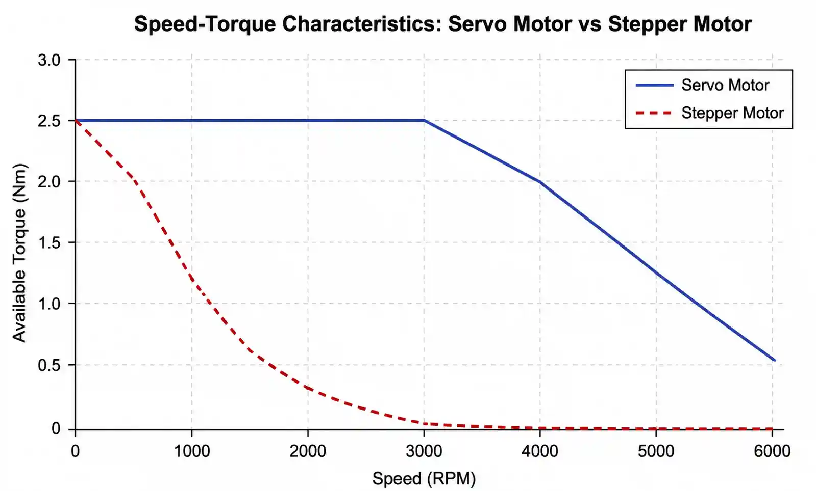
Servo motors deliver significantly higher speed and acceleration than steppers. While steppers typically operate below 2000 rpm and lose torque rapidly at higher speeds, servo motors maintain high torque across their entire speed range and can reach 6000 rpm or more. This makes servos the clear choice for high-throughput applications and rapid-cycle machines.
Torque-to-inertia ratio favors servo motors, resulting in faster acceleration and shorter cycle times. Servo motors also provide smooth, quiet operation across the entire speed range, while steppers can exhibit resonance and vibration at certain speeds unless tuned with microstepping or dampers.
Energy efficiency is another servo advantage. Steppers draw full current continuously to maintain holding torque, even when stationary. Servo motors draw current only as needed to maintain position or move the load, reducing power consumption and heat generation in the control cabinet.
Cost and Complexity
Stepper motors cost significantly less than servo motors of comparable size, and stepper drives are simpler and cheaper than servo drives. For low-performance applications with predictable loads and modest speed requirements, steppers offer an attractive cost advantage.
Servo systems require tuning of PID gains and velocity/acceleration limits to achieve stable, responsive performance. Stepper systems require no tuning but may need microstepping and resonance damping for smooth operation.
| Criteria | Stepper Motor | Servo Motor |
|---|---|---|
| Control Method | Open-loop (no feedback) | Closed-loop (encoder feedback) |
| Speed Range | Up to 2000 rpm typical | Up to 6000+ rpm |
| Torque at High Speed | Drops significantly above 1000 rpm | Maintains torque to rated speed |
| Positioning Accuracy | ±5% step angle (no error correction) | Arc-seconds with feedback |
| Acceleration | Moderate (limited by inertia) | High (better torque-to-inertia ratio) |
| Energy Efficiency | Lower (continuous current) | Higher (current on demand) |
| Initial Cost | Lower | Higher |
| Tuning Required | No | Yes (PID gains) |
| Typical Applications | 3D printers, basic positioning, low-speed automation | CNC machines, robotics, high-speed packaging, precision assembly |
The key decision factor is application performance requirements. If your application demands high speed, rapid acceleration, dynamic load handling, or verified positioning accuracy, servo motors justify their higher cost. If loads are predictable, speeds are modest, and cost is critical, steppers provide adequate performance at lower investment.
5. Design Considerations and Common Pitfalls
Proper servo motor integration requires attention to electrical, mechanical, and thermal design details. The following considerations help avoid the most common design mistakes that lead to poor performance or premature failure.
Mechanical Integration
Proper shaft coupling selection is critical. Rigid couplings transmit maximum torque and positioning accuracy but require precise alignment to prevent bearing damage. Flexible couplings tolerate minor misalignment but introduce backlash and compliance that degrades positioning performance. For precision applications, use bellows or disc couplings with minimal backlash and high torsional stiffness.
Mounting stiffness affects system resonance and positioning accuracy. Mount servo motors to rigid structures using properly torqued fasteners. Avoid cantilevered loads that create side loads on motor bearings, shortening bearing life.
When using gearboxes, select high-quality planetary or harmonic drive reducers with minimal backlash. Backlash in the drivetrain directly translates to positioning error. For servo applications, specify gearboxes with backlash below 5 arc-minutes.
Electrical Wiring and Grounding
Proper cable routing prevents electromagnetic interference (EMI) that can corrupt encoder signals and cause positioning errors or faults. Run motor power cables and encoder signal cables in separate conduits. Use shielded twisted-pair cable for encoder signals and connect shield to drive ground at one end only to avoid ground loops.
Ensure adequate wire gauge for motor power cables to minimize voltage drop, especially for long cable runs. Excessive voltage drop reduces available torque and can cause drive undervoltage faults. Consult drive manufacturer specifications for maximum cable length and minimum wire gauge.
Install servo drives in climate-controlled enclosures with adequate ventilation or forced cooling. Most servo drives are designed for ambient temperatures up to 40-45°C. Operating above this range triggers thermal derating or protection shutdowns.
Thermal Management
Servo motors generate heat during operation, and excessive temperature shortens winding insulation life and bearing grease life. Most industrial servo motors have insulation class F (155°C) or class H (180°C), but should operate well below these limits for long service life.
Duty cycle affects thermal loading. A motor that can deliver 10 Nm continuously may handle 20 Nm peak torque for short durations. Calculate the RMS torque for your duty cycle and verify it remains below the motor's continuous rating. Many servo drives include thermal models that monitor motor temperature and prevent overheating.
For applications with high ambient temperature or continuous high-duty cycles, consider motors with forced cooling (external fan) or liquid cooling.
Common Design Mistakes
Ignoring inertia ratio during motor selection leads to tuning difficulties and sluggish response. Always calculate load inertia and verify the inertia ratio falls within acceptable range, ideally below 5:1 for demanding applications.
Failing to account for reflected inertia through gears or screws can result in undersized motors. A 10 kg linear mass on a 5 mm/rev ball screw reflects to approximately 0.00006 kg·m² at the motor shaft, which may seem small but adds up quickly with multiple axes or larger masses.
Specifying peak torque without checking speed-torque curves is another frequent error. A motor may provide 20 Nm peak torque, but only at low speeds. At 3000 rpm, available torque may drop to 8 Nm. Always verify that required torque is available at the maximum operating speed.
Neglecting cable length limits can corrupt encoder feedback or cause voltage drop issues. Follow drive manufacturer specifications for maximum motor cable length, typically 25-50 meters for standard drives.
6. Supply Chain and Sourcing Considerations
Beyond technical specifications, practical sourcing factors affect project timelines, costs, and long-term supportability. Engineers and procurement teams should evaluate these factors early in the selection process.
Lead Times and Availability
Standard servo motors from major manufacturers (Siemens, Yaskawa, Mitsubishi, Kollmorgen, Fanuc) typically have lead times of 4-12 weeks depending on size and configuration. Custom motors with special windings, mounting configurations, or encoder types can extend lead times to 16-20 weeks.
During supply chain disruptions or periods of high demand, lead times can extend significantly. For critical projects, consider dual sourcing from multiple manufacturers or maintaining strategic inventory of long-lead components.
Many distributors (Digi-Key, Mouser, Allied Electronics) stock popular servo motor models for immediate delivery, though selection is limited compared to ordering direct from manufacturers. For prototyping and development, distributor stock accelerates schedules.
Certifications and Compliance
Industrial servo motors typically carry CE marking for European markets and UL recognition for North American markets. For specialized applications, verify additional certifications:
- AEC-Q200 or equivalent for automotive applications requiring extended temperature range and vibration resistance
- IEC 60601 for medical device applications
- ATEX or IECEx for explosive atmosphere environments
- IP ratings (IP54, IP65, IP67) for washdown or outdoor installations
Missing certifications can delay product launches or prevent market entry. Verify certification requirements early and select motors with appropriate approvals.
Total Cost of Ownership
Initial motor cost represents only part of the total cost equation. Consider:
- Drive cost: high-performance motors may require more expensive drives with advanced features
- Energy cost: more efficient motors reduce operating costs over the equipment's lifetime
- Maintenance cost: brushless servo motors require minimal maintenance compared to brushed DC motors
- Spare parts availability: motors from major manufacturers have better long-term parts support
For high-volume equipment builds, negotiate volume pricing and consider standardizing on a single motor family to reduce inventory complexity and improve technician familiarity.
| Sourcing Factor | Low-Cost Option | High-Performance Option |
|---|---|---|
| Lead Time | 4-8 weeks (standard models) | 12-20 weeks (custom specs) |
| Availability | Distributor stock available | Made to order |
| Certifications | CE, UL basic | AEC-Q, ATEX, IECEx, medical |
| IP Rating | IP54 (standard industrial) | IP65, IP67 (washdown, outdoor) |
| Price Range (1 Nm example) | $200-400 | $600-1200+ |
| Energy Efficiency | 80-85% typical | 90-94% (high-efficiency design) |
| Encoder Type | Incremental (lower cost) | Absolute multi-turn (premium) |
For commercial products, balance initial cost against performance requirements and total cost of ownership. For critical applications, prioritize reliability, support, and long-term availability over lowest purchase price.
7. FAQ
What is the difference between AC servo motors and DC servo motors?
AC servo motors use three-phase AC power and typically employ permanent magnet synchronous (PMSM) or brushless DC (BLDC) designs. They offer higher power density, better thermal performance, and maintenance-free operation due to the absence of brushes. DC servo motors use brushed or brushless DC designs and are simpler to control but require periodic brush replacement in brushed variants. For new industrial designs, AC servo motors are the standard choice.
How do I calculate the required servo motor torque for a ball screw application?
Calculate total torque as the sum of acceleration torque, friction torque, and gravitational torque (for vertical axes). Acceleration torque is T = J_total × α. Friction torque for ball screws is approximately 5-10% of gravitational load. Gravitational torque for vertical motion is T = m × g × (lead/2π). Reflect all linear forces and masses to the motor shaft using the screw lead, then add a 20-50% safety factor.
What inertia ratio should I target when selecting a servo motor?
Traditional design practice recommends inertia ratios between 1:1 and 10:1, with lower ratios providing better dynamic response and easier tuning. Modern servo drives with adaptive tuning can handle ratios up to 30:1 or higher, but tuning becomes more challenging and system response degrades. For demanding applications requiring rapid acceleration and precise positioning, target ratios below 5:1.
Can I use a servo motor in a vacuum or cleanroom environment?
Standard servo motors use grease-lubricated bearings that outgas in vacuum and may contain particulates unsuitable for cleanrooms. For vacuum applications, specify motors with dry-lubricated bearings or magnetic bearings. For cleanrooms, select motors with sealed housings (IP65 or higher) and cleanroom-compatible materials. Some manufacturers offer specialized motors designed specifically for these environments.
How long do servo motors typically last?
Servo motor life is primarily limited by bearing life and winding insulation degradation. Under normal operating conditions (proper loading, appropriate ambient temperature, clean environment), servo motor bearing life is typically 20,000 to 30,000 operating hours. Winding insulation life depends on operating temperature; motors run at rated temperature may last 40,000+ hours. Operating below rated temperature significantly extends insulation life per the Arrhenius equation.
What is the meaning of motor constant (Kt) and voltage constant (Ke)?
The torque constant (Kt) defines the relationship between motor current and output torque: T = Kt × I. Higher Kt motors produce more torque per amp, improving efficiency but typically at the cost of lower maximum speed. The voltage constant (Ke) defines the back-EMF generated per unit speed: V = Ke × ω. These constants are related by Kt = Ke in consistent units and represent fundamental motor design characteristics that affect performance across the operating range.
Should I choose an incremental or absolute encoder?
Incremental encoders measure relative position change and require homing after each power cycle to establish a position reference. They cost less and suffice for applications where homing is acceptable. Absolute encoders report position directly after power-up without homing, eliminating the need for limit switches and homing routines. They cost more but reduce startup time and prevent crashes. For multi-turn applications, select multi-turn absolute encoders that track position across multiple shaft revolutions.
How do I troubleshoot servo motor overheating?
First verify that calculated RMS torque remains below the motor's continuous rating. Check for mechanical binding, excessive friction, or misalignment that forces the motor to work harder than expected. Verify adequate ventilation around the motor and ensure ambient temperature remains within specifications. Inspect drive tuning parameters—excessive integral gain can cause continuous current flow even when the motor appears stationary. Measure actual motor current during operation to verify it matches expectations.
8. Conclusion
Choosing a servo motor isn’t rocket science—but you do need to match torque, speed, inertia, and feedback resolution to what your machine actually does. If you need high speed, fast acceleration, and precise positioning under changing loads, servo is worth the extra cost. For simpler, slower, steady‑load jobs, a stepper can do the job for less money.
Before you buy, run the numbers: torque across the whole cycle, torque at max speed, inertia ratio, and encoder resolution. Don’t forget the common traps—ignoring the speed‑torque curve, forgetting reflected inertia, or underestimating cable length limits.For critical projects, get the motor vendor’s apps engineer involved early. They’ll check your math, suggest the right frame size, and flag integration gotchas before they bite you. Grab datasheets and app notes, and if you can, test with an eval kit before committing to volume.
Ready to pick a motor? Use the calculation steps we covered, compare a few brands, and ask your vendor to review your choice. It saves headaches down the road.